EP0811128B1 - Methode de raccordement de conduites avec revetement interne et conduites raccordees par cette methode - Google Patents
Methode de raccordement de conduites avec revetement interne et conduites raccordees par cette methode Download PDFInfo
- Publication number
- EP0811128B1 EP0811128B1 EP96903138A EP96903138A EP0811128B1 EP 0811128 B1 EP0811128 B1 EP 0811128B1 EP 96903138 A EP96903138 A EP 96903138A EP 96903138 A EP96903138 A EP 96903138A EP 0811128 B1 EP0811128 B1 EP 0811128B1
- Authority
- EP
- European Patent Office
- Prior art keywords
- fitting
- liner
- pipe
- ring
- fittings
- Prior art date
- Legal status (The legal status is an assumption and is not a legal conclusion. Google has not performed a legal analysis and makes no representation as to the accuracy of the status listed.)
- Expired - Lifetime
Links
Images


Classifications
-
- F—MECHANICAL ENGINEERING; LIGHTING; HEATING; WEAPONS; BLASTING
- F16—ENGINEERING ELEMENTS AND UNITS; GENERAL MEASURES FOR PRODUCING AND MAINTAINING EFFECTIVE FUNCTIONING OF MACHINES OR INSTALLATIONS; THERMAL INSULATION IN GENERAL
- F16L—PIPES; JOINTS OR FITTINGS FOR PIPES; SUPPORTS FOR PIPES, CABLES OR PROTECTIVE TUBING; MEANS FOR THERMAL INSULATION IN GENERAL
- F16L58/00—Protection of pipes or pipe fittings against corrosion or incrustation
- F16L58/02—Protection of pipes or pipe fittings against corrosion or incrustation by means of internal or external coatings
- F16L58/04—Coatings characterised by the materials used
- F16L58/10—Coatings characterised by the materials used by rubber or plastics
- F16L58/1009—Coatings characterised by the materials used by rubber or plastics the coating being placed inside the pipe
- F16L58/1045—Coatings characterised by the materials used by rubber or plastics the coating being placed inside the pipe the coating being an extruded or a fused layer
-
- F—MECHANICAL ENGINEERING; LIGHTING; HEATING; WEAPONS; BLASTING
- F16—ENGINEERING ELEMENTS AND UNITS; GENERAL MEASURES FOR PRODUCING AND MAINTAINING EFFECTIVE FUNCTIONING OF MACHINES OR INSTALLATIONS; THERMAL INSULATION IN GENERAL
- F16L—PIPES; JOINTS OR FITTINGS FOR PIPES; SUPPORTS FOR PIPES, CABLES OR PROTECTIVE TUBING; MEANS FOR THERMAL INSULATION IN GENERAL
- F16L13/00—Non-disconnectable pipe joints, e.g. soldered, adhesive, or caulked joints
- F16L13/02—Welded joints
- F16L13/0254—Welded joints the pipes having an internal or external coating
- F16L13/0263—Welded joints the pipes having an internal or external coating having an internal coating
-
- F—MECHANICAL ENGINEERING; LIGHTING; HEATING; WEAPONS; BLASTING
- F16—ENGINEERING ELEMENTS AND UNITS; GENERAL MEASURES FOR PRODUCING AND MAINTAINING EFFECTIVE FUNCTIONING OF MACHINES OR INSTALLATIONS; THERMAL INSULATION IN GENERAL
- F16L—PIPES; JOINTS OR FITTINGS FOR PIPES; SUPPORTS FOR PIPES, CABLES OR PROTECTIVE TUBING; MEANS FOR THERMAL INSULATION IN GENERAL
- F16L33/00—Arrangements for connecting hoses to rigid members; Rigid hose-connectors, i.e. single members engaging both hoses
- F16L33/20—Undivided rings, sleeves, or like members contracted on the hose or expanded inside the hose by means of tools; Arrangements using such members
- F16L33/213—Undivided rings, sleeves, or like members contracted on the hose or expanded inside the hose by means of tools; Arrangements using such members only a sleeve being expanded inside the hose
-
- Y—GENERAL TAGGING OF NEW TECHNOLOGICAL DEVELOPMENTS; GENERAL TAGGING OF CROSS-SECTIONAL TECHNOLOGIES SPANNING OVER SEVERAL SECTIONS OF THE IPC; TECHNICAL SUBJECTS COVERED BY FORMER USPC CROSS-REFERENCE ART COLLECTIONS [XRACs] AND DIGESTS
- Y10—TECHNICAL SUBJECTS COVERED BY FORMER USPC
- Y10T—TECHNICAL SUBJECTS COVERED BY FORMER US CLASSIFICATION
- Y10T29/00—Metal working
- Y10T29/49—Method of mechanical manufacture
- Y10T29/49428—Gas and water specific plumbing component making
Definitions
- the invention relates to joining lined pipe items, and to pipe fittings for use in such joining.
- the invention relates to joining pipes which have a lining, particularly a close-fit lining of polyethylene or other thermoplastic material.
- the pipes can be intended for use in conveying in particular for example liquid hydrocarbons containing carbon dioxide, hydrogen sulphide, methane or hydrocarbons.
- the liquid conveyed may be at a temperature of, for example, a value up to 160°C and may be at a pressure of, for example, a value up to 345 bar (5000 pounds per square inch).
- the liquid conveyed may include exclusively, or in conjunction with the hydrocarbons, non-deaerated water; or brine.
- the pipes can be intended to convey liquids which have a very deleterious effect on the material normally used for pipes. That material is usually metal, for example ferrous metal which may be steel or cast-iron.
- the pipes therefore are fitted with a liner of thermoplastic material to reduce the effect of the liquid conveyed upon the pipe.
- Such lined pipes have to be joined, at intervals, in order to allow a long pipeline to be built.
- pipeline includes other pipelike items, such as valves.
- pipe item means pipes and other pipelike items such as valves, for example.
- United States patent No.5009737 (Lescaut - assigned to Atochem) describes a method of producing a pipeline arrangement comprising positioning pipes end-to-end with an internal covering terminating axially inwardly of the axial ends to define an uncovered inner wall section situated between adjacent longitudinal end of said coverings, welding the ends of the pipes together, introducing a strip of fusible material radially inside of said uncovered wall section, and heating the strip while applying radially outwardly directed pressure to the strip to push the strip against said uncovered wall section to reduce the thickness of the strip and increase the longitudinal width of the strip to cause the strip to contact the adjacent ends of the coverings and completely cover the uncovered wall section and to weld the strip to the coverings.
- each of two adjoining pipes has a covering composed of polyamide thermoplastic material.
- Each pipe adjacent its end is free from covering. The two adjacent ends of the pipes are welded together.
- the strip is also composed of polyamide thermoplastic material and has an initial thickness of 6 mm and is 80 mm wide.
- the pipes adjacent their ends are heated by an induction heating unit to a temperature of 200°C while a pressure of 20kPa is applied to the inner face of the strip.
- a pressure of 20kPa is applied to the inner face of the strip.
- the pressure is applied to the strip by four blades movable radially by four hydraulic rams on a self-propelled carriage movable inside the pipes.
- This carriage is equipped with means for detecting the part of the pipes (in which the carriage is travelling) which is free from coverings.
- a radioactive isotope may be provided or a mechanical feeler as the means.
- US patent No.5009737 envisaged the use of a liner as a covering.
- a liner is a one-piece pipe-like member which is drawn into the steel pipe.
- the covering described in US patent No.5009737 is a covering applied progressively to the pipe in particulate form.
- Alternative forms of covering are mentioned, including centrifuged cement and bitumens.
- US patent No.5009737 comprises welding the metal pipes together first of all followed by fusion welding of the strip to the coverings of the two pipes using a tool operating on the inside of the pipes.
- United States patent No.4611833 (Lescaut - assigned to Atochem) describes a pipeline internally coated with heat sensitive material to protect the interior of the pipe from corrosion or abrasion and comprising at least two pipe sections connected by a welded joint wherein the interior of each metal pipe is coated with a stainless metal alloy for a distance of from one-half to three pipes diameters from the end of the pipe and there is a reserved zone at the end of the pipe which is free of the heat sensitive material, the heat sensitive coating overlapping the stainless metal alloy coating for at least 20 millimetre from the end of the pipe, the edge of each section being coated with the stainless alloy and constituting the welded joint between the two pipe sections, the pipe sections being joined together by the bond formed by stainless alloy with the edges of the pipe and further bonded by an outer weld of metal which is of substantially the same metal as the metal comprising the pipe.
- stainless ferrochromium alloy with a thickness of 500 microns is applied to the interior wall and edge of a 200 mm diameter pipe over a length of 120 mm measured from the end of the pipe.
- the covering is not a liner but is a covering composed of polyamide-11 deposited electrostatically to attain a thickness of 600 microns, leaving an uncoated reserve zone of 80 mm from the end of the pipe section.
- the method described involves the use of an induction unit arranged around the pipes at each joint. Again, this presupposes that each joint is made every 15m or less along the pipe.
- US patent No. 4611833 describes a process which requires internal deposition of a stainless metal coating at the end of each pipe followed by deposition by an electrostatic process or by dipping or rotary casting. Again, such a process requires the length of pipe to be limited to a length of 15m or so. Joints therefore have to be made every 15m in order to make a pipeline.
- WO 95/27166 discloses a method of axially joining two pipes using a sleeve of non-metallic material arranged to be inserted into the adjacent ends of the two pipes.
- a plurality of seal rings are located on the outer circumference of the sleeve to seal the sleeve to the interior surface of each pipe.
- a method of joining two pipe items comprises joining to an end of each pipe item a tubular metal fitting, each fitting having an internal surface formed of corrosion resistant metal which extends to the free end of the fitting characterised by the internal surface having grooves separated by castellations, lining each pipe item and at least a portion of each fitting joined thereto with a thermoplastic liner, forcing a respective ring of corrosion resistant metal into each fitting to compress each liner and force it into the grooves of the fitting that it lines and joining the fittings by welding.
- an alternative method uses a respective undersize ring which is accommodated in each fitting and then the ring is forced outwardly so as to compress the liner and force it into the grooves of the fitting.
- the fitting may have an external flange at its free end, and instead of joining the fittings by welding the fittings are joined by bolts passing through the flanges of the fittings.
- One of the pipe items may itself be made of corrosion resistant metal and may have an external flange and the fitting and said one pipe item are joined by bolts passing through the flanges said one pipe item not containing a liner or ring.
- the invention also includes two pipe items joined together by the method according to the invention as disclosed in claim 6.
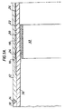
- Figures 1A and 1B show one of two pipe items 10. Each item in this case is a steel pipe.
- the other pipe (not shown) is joined to a right hand end of a right-hand fitting shown in the figure and described below.
- the pipe 10, and the other pipe is composed of carbon steel.
- Each pipe 10 is joined to a tubular carbon steel fitting 12 by an annular girth weld 14.
- the two fittings 12 are joined by an annular girth weld 15.
- each fitting 12 is relieved at 16 and corrosion resistant high alloy cladding material 18 is deposited as a weld deposit upon the fitting 12.
- the material is e.g. Inconel 625 weld deposit material.
- the internal surface of the material 18 is subsequently machined to form a series of internal, annular grooves 20 separated by internal, annular castellations 22.
- the internal surface of the material 18 is machined to provide a wider groove 24.
- the internal surface of the material 18 is machined to provide a recess 26.
- Each pipe 10 contains a tubular liner 30.
- the liners 30 are composed of medium density polyethylene.
- the liners 30 are a close fit inside the pipes 10 and are installed by any method of installing close fit liners.
- the preferred method is the "swagelining" process.
- "Swagelining” is a Trade Mark of British Gas plc. In this process the polyethylene liner is pulled through a die which reduces the diameter of the liner. Then the liner is pulled through the steel pipe. The liner is allowed to relax and after a period of time the liner reverts its original diameter and becomes a close fit in the pipe.
- Each liner 30 is compressed in the region of the grooves 20 and castellations 22 by a ring 32, which can be of suitable metal, having a corrosion resistant external coating 33 formed for example of a cladding of Inconel 625 weld deposit material.
- the ring 32 is entirely composed of stainless steel. Each ring 32 has been forced into the fitting 12 and forces the liner 30 into the grooves 20.
- Each liner 30 terminates short of the end of the fitting 12 and an annulus 40 of liner material is accommodated in the gap between the ends of the two liners 30.
- the annulus 40 has an external annular groove 42 in which is received an annular body 44 of heat insulation material.
- the preferred material is obtainable from Burnstone Ceramic Limited of 19 Redgates, Walkington, Beverly, North Humberside HU17 8TS United Kingdom under the description Refractory Sheet Type A Moldable.
- the material comprises a mixture of aluminium oxide and alumino-silicate fibres with some 35-40% water which it loses when it dries, 1% of organic binder and a trace of ammonia.
- the material in the form of a rectangular strip is readily formed into an annular body 44 and the two ends pressed together. After shaping and moulding the ends of the strip, the strip can be heated to dry it after which a hard body 44 results.
- the body 44 bridges the annular girth weld 15 between the fittings 12 and protects the underlying ring 40 of liner material.
- Figure 2 shows details of the grooves 20 and the castellations 22 in the fittings 12.
- the following are the values of the features listed:- Feature Value Angle A 30° Width of castellation B 3 millimetres Pitch of castellation C 9.3 millimetres Radius on castellation D 1.0 millimetres
- the pipes 10 have an external diameter of 219.1 mm and an internal diameter of 200 mm.
- Each fitting 12 is 500 mm long.
- the pipes 10 are each 0.5 to 1.0 kilometre in length.
- a typical requirement would be 2 or 3 joints between lined pipes in total.
- the advantage of the method according to the invention is that such a pipeline is fabricated using for the most part carbon steel which is much cheaper than using high alloy (Duplex) steel throughout or using corrosion inhibitors.
- annulus 40 is optional. It is included because of the possibility that a pig will be used in the pipeline and when the pig traverses the gap between the end of the liners 30 (in the absence of the annulus 40) some damage might result to the pig. If pigging is known not to be required then the annulus 40 can be omitted.
- FIG. 3 shows a modified form of fitting 50.
- the fitting 50 is entirely composed of Duplex stainless steel or other corrosion resistant metal.
- Two fittings 50 are joined to the pipes 10 by welding instead of using the fittings 12.
- the welds at 14 are made using filler material which is compatible with the Duplex steel and the weld at 15 is made with a suitable filler material between the two Duplex fittings.
- Figure 4 shows the pipe 10 and the fitting 50 joined to it by welding 14.
- the liner 30 has already been inserted through the pipe 10 and the fitting 50.
- the ring 32 has an outer diameter greater than the inner diameter of the liner 30.
- the ring 32 is forced into place using an hydraulic cylinder 60 which reacts against a plate 62 connected by tie rods 64 to a clamping assembly 66 arranged around the fitting 50.
- the assembly 66 includes wedges 68, connected to the tie rods 64, and reacting against inner wedges 70 and engaging the fitting 50.
- the piston rod 72 of the cylinder 60 acts on a loading plate 74 engaging the ring 32.
- Silicone grease is smeared over the outside of the ring 32, which reduces friction and makes the insertion of the ring 32 into the liner 30 relatively easy and greatly reduces the force necessary to compress the liner 30 and force it into the grooves 20.
- the liner 30 is cut to its final length i.e. level with the free end of the fitting 50. If instead of the type of fitting 50, the type of fitting 12 shown in Figure 1 were used, the liner 30 would be cut to its final length inside the fitting, as shown in Figure 1.
- Figure 5 shows an alternative form of ring used for compressing the liner 30 and forcing it into the grooves 20.
- the ring 80 is initially of smaller outer diameter than the inner diameter of the liner 30.
- the parts are shown in Figure 5 in the positions which they occupy immediately before the ring is expanded to compress the liner 30.
- the ring is placed in position opposite the grooves 20 and as hydraulic cylinder 82 is used to force the ring 80 outwardly.
- the ring 80 is strained beyond its elastic limit and compresses the liner 30 between itself and the castellations 22 of the fitting 50.
- the ring 80 is made of stainless steel or other corrosion resistant metal.
- the cylinder 82 has a piston rod 84 connected to wedges 86 (only one of which is shown).
- the wedges 86 act on further wedges 88 (only one of which is shown).
- the wedges 88 act on the ring 80.
- Figure 6 shows yet another alternative method of using a ring to force the liner 30 into the grooves 20 in the fitting 50.
- the ring 90 is initially of smaller outer diameter than the inner diameter of the liner 30.
- Figure 6 the parts are shown immediately before the ring is expanded.
- a mandrel 91 is inserted in the liner 30.
- the extreme left-hand end (as viewed in Figure 6) of the mandrel 91 has a diameter approximately equal to the inner diameter of the liner 30.
- the mandrel 91 is attached to a pull-rod 92 connected to an hydraulic cylinder (not shown).
- the ring 90 is placed in position opposite the grooves 20 and then a tubular steel member 94 of the same outer diameter as the ring 90, is positioned to the right of the ring 90 as viewed in the Figure.
- the member 94 is restrained against rightward movement.
- the hydraulic cylinder is operated to draw the mandrel 91 rightward (as viewed in Figure 6) over the ring 90.
- the ring 90 is expanded outwardly past its elastic limit.
- the thickness of the ring 90 is chosen so that, when it has been expanded by the mandrel 91, it compresses the liner 30 between itself and the castellations 22 and forces the liner 30 into the grooves 20.
- the member 94 is removed from the liner 30 and then the mandrel 91 can be removed also from the liner 30.
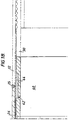
- Figure 7 shows a modified form of fitting which can be used where the pipe is required to be joined to some other pipelike item, such as a valve. In such a case joining is required to be by way of a bolted assembly instead of joining the parts by welding.
- the fitting 100 in this case has an integral, external flange 102 having a working face 104 which extends radially outwardly from the end of the fitting remote from the end which is welded at 14 to the pipe 10.
- the fitting 100 is relieved at 116 and corrosion resistant high alloy cladding material 118 is deposited as a weld deposit upon the fitting 100 over the area of relieving 116.
- the fitting 100 is also relieved at 120 over the working face 120 including the formation of an annular groove 122.
- the cladding 118 is deposited in one contiguous layer not only over the area 116 but also the area of relieving 120 including the groove 122.
- the cladding 118 also forms an annular groove 124 over the groove 122.
- the groove 124 partly accommodates a steel ring-type joint 126. This joint is also partly accommodated in a corresponding groove 128 in the working face 130 of the other pipe item 132.
- the other pipe item 132 may be identical with the fitting 100. Alternatively, the other pipe item 132 may be wholly made of corrosion resistant metal, such as stainless steel, for example.
- the flange 102 has bolt holes 136 (only one of which is shown).
- the fitting 100 is joined to the other fitting 132, or to the other pipe item 132, by bolts (not shown) which are passed through the bolt holes 136 fitted with nuts (not shown) and drawn tight.
- the steel joint 126 is compressed between the flanges.
- the whole of the fitting may be made of corrosion resistant metal (e.g. stainless steel for example). In that case, of course, no cladding would be used.
- corrosion resistant metal e.g. stainless steel for example
- fitting shown in Figure 7 has been described as being used to join a pipe to some other kind of pipelike item, the fitting shown in Figure 7 can, of course, be used to join two pipes.
- any of the pipe items 10, or fittings 12, 50 or 100 may be of cast-iron, and any welding involving such cast-iron articles will be performed in known manner appropriate to cast-iron.
Landscapes
- Engineering & Computer Science (AREA)
- General Engineering & Computer Science (AREA)
- Mechanical Engineering (AREA)
- Non-Disconnectible Joints And Screw-Threaded Joints (AREA)
- Lining Or Joining Of Plastics Or The Like (AREA)
- Protection Of Pipes Against Damage, Friction, And Corrosion (AREA)
- Thermal Insulation (AREA)
- Rigid Pipes And Flexible Pipes (AREA)
- Control Of Driving Devices And Active Controlling Of Vehicle (AREA)
- Pressure Welding/Diffusion-Bonding (AREA)
- Branch Pipes, Bends, And The Like (AREA)
Claims (7)
- Procédé de raccordement de deux éléments de canalisation (10), le procédé comprenant les étapes consistant à raccorder à une extrémité de chaque élément de canalisation (10) un raccord de tuyauterie métallique tubulaire (12 ; 50), chaque raccord de tuyauterie (12 ; 50) présentant une surface interne réalisée à partir d'un métal résistant à la corrosion (18) qui s'étend vers l'extrémité libre du raccord de tuyauterie (12 ; 50), la surface interne comportant des gorges (20) séparées par des créneaux (22), chemiser chaque élément de canalisation (10) et au moins une partie de chaque raccord de tuyauterie (12 ; 50) raccordé à celui-ci à l'aide d'une chemise thermoplastique (30), forcer une bague respective (32) de métal résistant à la corrosion dans chaque raccord de tuyauterie (12 ; 50) pour comprimer chaque chemise (30) et la forcer dans les gorges (20) du raccord de tuyauterie (12 ; 50) qu'elle chemise et raccorder les raccords de tuyauterie (12 ; 50) par soudage.
- Procédé selon la revendication 1, dans lequel après le chemisage de chaque élément de canalisation (10), la chemise (30) dans chaque cas est autorisée à se détendre pendant un certain temps, puis une bague respective (32) est forcée dans chaque raccord de tuyauterie (12 ; 50) et la chemise est coupée ensuite dans chaque cas à la longueur finale.
- Procédé selon la revendication 1 ou la revendication 2, dans lequel la chemise (30), dans le cas de chaque élément de canalisation (10), est coupée à l'intérieur du raccord de tuyauterie (12 ; 50) qu'elle chemise en laissant une longueur de raccord de tuyauterie non chemisée puis, avant le raccordement des raccords de tuyauterie (12 ; 50) par soudage, un anneau de matériau de chemise (40) est disposé à l'intérieur d'un raccord de tuyauterie (12 ; 50) et s'étend depuis celui-ci, et l'autre raccord de tuyauterie (12 ; 50) est tiré par-dessus l'anneau (40), l'anneau (40) comportant une gorge externe (42) qui loge un corps annulaire (44) de matériau isolant protégeant l'anneau sous-jacent de matériau de chemise (40) lorsque les raccords de tuyauterie (12 ; 50) sont raccordés par la suite par soudage.
- Procédé selon l'une quelconque des revendications 1 à 3, dans lequel au lieu d'utiliser une bague respective (32) qui est forcée dans le raccord de tuyauterie (12 ; 50), une bague respective au diamètre plus petit (80 ; 90) est logée dans chaque raccord de tuyauterie (12 ; 50), puis la bague (80 ; 90) est forcée vers l'extérieur de façon à comprimer la chemise (30) et à la forcer dans les gorges (20) du raccord de tuyauterie (12 ; 50).
- Procédé selon l'une quelconque des revendications précédentes, dans lequel chaque raccord de tuyauterie (100) comporte une bride externe (102) à son extrémité libre et dans lequel au lieu de raccorder les raccords de tuyauterie par soudage, les raccords de tuyauterie (100) sont raccordés par des boulons traversant les brides (102) des raccords de tuyauterie (100), ou bien l'un (132) des deux éléments de canalisation est réalisé lui-même à partir d'un métal résistant à la corrosion et ne comporte aucun raccord de tuyauterie, mais comporte une bride externe et le raccord de tuyauterie (100) ainsi que ledit un élément de canalisation (132) sont raccordés par des boulons traversant les brides, ledit un élément de canalisation (132) ne contenant pas de chemise ni de bague.
- Deux éléments de canalisation (10) raccordés l'un à l'autre par le procédé selon l'une quelconque des revendications précédentes, une extrémité de chaque élément de canalisation (10) étant soudée à la première extrémité d'un raccord de tuyauterie métallique tubulaire (12 ; 50) présentant une surface interne réalisée à partir d'un métal résistant à la corrosion (18), ladite surface comportant des gorges internes (20) séparées par des créneaux (22), et les autres extrémités des deux raccords de tuyauterie (12 ; 50) étant raccordées par soudage, chaque élément de canalisation et au moins une partie de chaque raccord de tuyauterie (12 ; 50) contenant une chemise de matériau thermoplastique (30), chaque chemise (30) étant comprimée dans chaque raccord de tuyauterie (12 ; 50) par une bague respective (32 ; 80 ; 90) de métal résistant à la corrosion, la chemise (30) étant forcée dans chaque cas dans les gorges (20) dans le raccord de tuyauterie (12 ; 50).
- Éléments de canalisation selon la revendication 6, les deux chemises (30) étant séparées par un anneau (40) de matériau de chemise qui comporte une gorge externe (42) logeant un corps annulaire (44) de matériau isolant chevauchant le raccord soudé entre les raccords de tuyauterie (12 ; 50).
Applications Claiming Priority (5)
| Application Number | Priority Date | Filing Date | Title |
|---|---|---|---|
| GBGB9503679.4A GB9503679D0 (en) | 1995-02-23 | 1995-02-23 | Joining lined pipes |
| GB9503679 | 1995-02-23 | ||
| GB9523726 | 1995-11-20 | ||
| GBGB9523726.9A GB9523726D0 (en) | 1995-11-20 | 1995-11-20 | Joining lined pipe items |
| PCT/GB1996/000411 WO1996026384A1 (fr) | 1995-02-23 | 1996-02-22 | Assemblage de conduites doublees |
Publications (2)
| Publication Number | Publication Date |
|---|---|
| EP0811128A1 EP0811128A1 (fr) | 1997-12-10 |
| EP0811128B1 true EP0811128B1 (fr) | 2002-08-14 |
Family
ID=26306574
Family Applications (1)
| Application Number | Title | Priority Date | Filing Date |
|---|---|---|---|
| EP96903138A Expired - Lifetime EP0811128B1 (fr) | 1995-02-23 | 1996-02-22 | Methode de raccordement de conduites avec revetement interne et conduites raccordees par cette methode |
Country Status (18)
| Country | Link |
|---|---|
| US (1) | US5992897A (fr) |
| EP (1) | EP0811128B1 (fr) |
| JP (1) | JP2868316B2 (fr) |
| AR (1) | AR001011A1 (fr) |
| AT (1) | ATE222340T1 (fr) |
| AU (1) | AU692676B2 (fr) |
| BR (1) | BR9607408A (fr) |
| CA (1) | CA2213248C (fr) |
| CZ (1) | CZ260897A3 (fr) |
| DE (1) | DE69622997T2 (fr) |
| DK (1) | DK0811128T3 (fr) |
| ES (1) | ES2181867T3 (fr) |
| GB (1) | GB2298256B (fr) |
| HU (1) | HU220015B (fr) |
| PL (1) | PL321889A1 (fr) |
| SK (1) | SK112697A3 (fr) |
| UA (1) | UA41444C2 (fr) |
| WO (1) | WO1996026384A1 (fr) |
Cited By (1)
| Publication number | Priority date | Publication date | Assignee | Title |
|---|---|---|---|---|
| ES2224824A1 (es) * | 2002-11-28 | 2005-03-01 | Iberfusion, S.L. | Metodo para realizar una transicion entre tuberias de acero y polietileno. |
Families Citing this family (32)
| Publication number | Priority date | Publication date | Assignee | Title |
|---|---|---|---|---|
| GB2319315B (en) * | 1996-11-09 | 2000-06-21 | British Gas Plc | A method of joining lined pipes |
| US6621037B2 (en) | 1997-10-16 | 2003-09-16 | Magna International Inc. | Welding material with conductive sheet and method |
| US6689982B2 (en) | 1997-10-16 | 2004-02-10 | Magna International, Inc. | Apparatus and method for welding aluminum tubes |
| US6713707B2 (en) * | 1997-10-16 | 2004-03-30 | Magna International, Inc. | Welding material and method without carrier |
| GB2343613B (en) * | 1998-11-10 | 2003-04-02 | Bellplex Ltd | Shelving systems and shelving assemblies |
| US6392193B1 (en) | 1999-04-30 | 2002-05-21 | Frank's Casing Crew And Rental Tools, Inc. | Single side girth welding apparatus and method |
| US6566624B2 (en) * | 2000-03-03 | 2003-05-20 | Magna International Inc. | Welding assembly with nestable conductive ends |
| ATE312640T1 (de) * | 2001-10-05 | 2005-12-15 | Boston Scient Ltd | Kompositführungsdraht |
| NL1019425C2 (nl) | 2001-11-23 | 2003-05-27 | Wavin Bv | Koppelsysteem. |
| GB2384535B (en) * | 2002-01-26 | 2005-06-29 | Coflexip Stena Offshore Ltd | A protective insert for a welded pipe joint |
| GB0217274D0 (en) * | 2002-07-25 | 2002-09-04 | Boreas Consultants Ltd | Pipe liner connector |
| GB2391597A (en) * | 2002-08-02 | 2004-02-11 | Stolt Offshore Sa | Method of and Apparatus for Interconnecting Lined Pipes |
| GB0217937D0 (en) | 2002-08-02 | 2002-09-11 | Stolt Offshore Sa | Method of and apparatus for interconnecting lined pipes |
| FR2888309B1 (fr) | 2005-07-05 | 2007-10-12 | Saipem S A Sa | Piece de raccordement de conduites comportant une chemise interne, procede de revetement et procede d'assemblage |
| FR2876773B1 (fr) | 2004-10-19 | 2007-02-02 | Saipem S A Sa | Conduite comportant une chemise interne, notamment conduite sous-marine |
| NL1028736C2 (nl) * | 2005-04-11 | 2006-10-16 | Euro Manchetten & Compensatore | Buisverbinding tussen een metalen buis en een kunststof buis. |
| NL2000891C2 (nl) * | 2007-10-02 | 2009-04-03 | Pipelife Nederland Bv | Verbindingsconstructie met een hogedrukpijpleiding en koppeling. |
| WO2009048772A1 (fr) * | 2007-10-08 | 2009-04-16 | Insituform Technologies, Inc. | Assemblage soudé pour conduite doublée et ses composants |
| DE102010052212A1 (de) * | 2010-11-24 | 2012-05-24 | Rosen Swiss Ag | Rohranordnung und Verfahren |
| WO2015057235A1 (fr) | 2013-10-17 | 2015-04-23 | Robe Lighting, Inc. | Système d'obturateur de cadrage amélioré pour luminaire |
| GB2538549B (en) * | 2015-05-21 | 2018-02-28 | Pioneer Lining Tech Limited | Joining lined pipe sections |
| GB2543026B (en) | 2015-09-04 | 2019-01-02 | Technip France | Improvements relating to polymer lined pipes |
| CN106322051A (zh) * | 2016-08-29 | 2017-01-11 | 延安中海石油工程技术开发有限公司 | 一种防腐管道及其连接方法 |
| WO2018160310A1 (fr) * | 2017-03-01 | 2018-09-07 | Fmc Technologies, Inc. | Inserts résistant à l'érosion pour équipement d'écoulement |
| GB2560732B (en) * | 2017-03-22 | 2021-07-21 | Radius Systems Ltd | High pressure fitting |
| BR102017018910A2 (pt) * | 2017-09-04 | 2019-03-19 | Jose Anisio De Oliveira E Silva | Anel compósito de suporte para soldas de topo e sistema que emprega o dito anel na fabricação de juntas de topo soldadas de seções tubulares metálicas revestidas internamente com materiais sensíveis ao calor |
| FR3085736B1 (fr) | 2018-09-10 | 2020-11-27 | Saipem Sa | Procede de realisation d'une conduite sous-marine en acier apte a vehiculer un fluide corrosif. |
| GB2588919B (en) | 2019-11-13 | 2022-01-26 | Flowlining Ltd | Improved methods for joining lined pipes and associated apparatus |
| US12253192B2 (en) | 2020-08-05 | 2025-03-18 | Lps Ip, Llc | Sealed pipeline connection, pipeline sleeve, and lockable pipeline seals and method of making same |
| WO2022031769A1 (fr) | 2020-08-05 | 2022-02-10 | Lps Ip, Llc | Raccord de pipeline étanche et manchon de pipeline surélevé, et procédé de fabrication de ceux-ci |
| RU2769328C1 (ru) * | 2021-10-18 | 2022-03-30 | Общество с ограниченной ответственностью "ЛУКОЙЛ-ПЕРМЬ" | Способ соединения секций футерованного трубопровода |
| GB2619728B (en) | 2022-06-14 | 2024-10-02 | Subsea 7 Ltd | Joining lined pipes |
Family Cites Families (18)
| Publication number | Priority date | Publication date | Assignee | Title |
|---|---|---|---|---|
| CA869436A (en) * | 1971-04-27 | W. Turner John | Coupling seal for lined tubular arrangement | |
| GB403932A (en) * | 1932-03-30 | 1934-01-04 | Mannesmann Ag | Improvements in or relating to the joining together of sections of metal pipe provided with one or more thin metal coverings |
| US2216839A (en) * | 1939-05-15 | 1940-10-08 | Scovill Manufacturing Co | Interlocking sleeve coupling |
| DE853686C (de) * | 1944-01-07 | 1952-10-27 | Westdeutsche Mannesmannroehren | Rohrstumpfschweissverbindung mit beiderseits aufgemufften Rohrenden und eingelegtem Nippel |
| US3046114A (en) * | 1955-03-01 | 1962-07-24 | Azoplate Corp | Diazo compounds and printing plates manufactured therefrom |
| FR1368296A (fr) * | 1963-06-20 | 1964-07-31 | Ferodo Sa | Dispositif d'assemblage de tuyaux métalliques soudés |
| GB1001939A (en) * | 1963-08-15 | 1965-08-18 | Taylor Tube Seal Inc | Improved method of lining pipes and of joining lined pipes |
| GB1299354A (en) * | 1969-03-05 | 1972-12-13 | Dunlop Holdings Ltd | Couplings for tubular members |
| DE3571683D1 (en) * | 1984-01-20 | 1989-08-24 | Kuroki Kogyosho Co | Corrosion resisting steel pipe and method of manufacturing same |
| FR2564938B1 (fr) * | 1984-05-24 | 1986-11-28 | Atochem | Nouveau raccord de tubes revetus interieurement et son procede de fabrication |
| WO1987001428A1 (fr) * | 1985-09-04 | 1987-03-12 | Allseas Engineering B.V. | Procede de raccordement de longueurs de tuyaux, raccord ainsi produit, et longueurs de tuyaux fabriquees par ce procede |
| FR2614086A1 (fr) * | 1987-04-16 | 1988-10-21 | Atochem | Tubes metalliques assembles par leurs extremites, procede de fabrication et appareillage pour sa mise en oeuvre |
| GB9009860D0 (en) * | 1990-05-02 | 1990-06-27 | Du Pont Canada | Joining of metallic pipe lined with thermoplastic polymer |
| US5326137A (en) * | 1991-09-24 | 1994-07-05 | Perfection Corporation | Gas riser apparatus and method |
| GB2264765B (en) * | 1992-02-27 | 1995-04-12 | British Gas Plc | Method of lining a pipeline |
| US5346261A (en) * | 1993-03-25 | 1994-09-13 | Tuboscope Vetco International, Inc. | Coupled pipe assembly having a tapered interior sleeve |
| US5566984A (en) * | 1994-04-01 | 1996-10-22 | Abbema; William D. | Cylindrical corrosion barrier for pipe connections |
| US5590914A (en) * | 1995-01-05 | 1997-01-07 | Perfection Corporation | Field assembled gas riser |
-
1996
- 1996-02-20 GB GB9603597A patent/GB2298256B/en not_active Expired - Lifetime
- 1996-02-22 EP EP96903138A patent/EP0811128B1/fr not_active Expired - Lifetime
- 1996-02-22 JP JP8525503A patent/JP2868316B2/ja not_active Expired - Fee Related
- 1996-02-22 HU HU9801445A patent/HU220015B/hu not_active IP Right Cessation
- 1996-02-22 UA UA97094694A patent/UA41444C2/uk unknown
- 1996-02-22 ES ES96903138T patent/ES2181867T3/es not_active Expired - Lifetime
- 1996-02-22 US US08/894,024 patent/US5992897A/en not_active Expired - Lifetime
- 1996-02-22 SK SK1126-97A patent/SK112697A3/sk unknown
- 1996-02-22 WO PCT/GB1996/000411 patent/WO1996026384A1/fr not_active Ceased
- 1996-02-22 DK DK96903138T patent/DK0811128T3/da active
- 1996-02-22 DE DE69622997T patent/DE69622997T2/de not_active Expired - Lifetime
- 1996-02-22 AU AU47282/96A patent/AU692676B2/en not_active Ceased
- 1996-02-22 CA CA002213248A patent/CA2213248C/fr not_active Expired - Fee Related
- 1996-02-22 BR BR9607408A patent/BR9607408A/pt not_active IP Right Cessation
- 1996-02-22 PL PL96321889A patent/PL321889A1/xx unknown
- 1996-02-22 CZ CZ972608A patent/CZ260897A3/cs unknown
- 1996-02-22 AT AT96903138T patent/ATE222340T1/de not_active IP Right Cessation
- 1996-02-22 AR ARP960101486A patent/AR001011A1/es not_active Application Discontinuation
Cited By (2)
| Publication number | Priority date | Publication date | Assignee | Title |
|---|---|---|---|---|
| ES2224824A1 (es) * | 2002-11-28 | 2005-03-01 | Iberfusion, S.L. | Metodo para realizar una transicion entre tuberias de acero y polietileno. |
| ES2224824B1 (es) * | 2002-11-28 | 2006-01-16 | Iberfusion, S.L. | Metodo para realizar una transicion entre tuberias de acero y polietileno. |
Also Published As
| Publication number | Publication date |
|---|---|
| BR9607408A (pt) | 1998-07-07 |
| JPH10503271A (ja) | 1998-03-24 |
| AU4728296A (en) | 1996-09-11 |
| US5992897A (en) | 1999-11-30 |
| DE69622997D1 (de) | 2002-09-19 |
| GB2298256B (en) | 1998-03-18 |
| WO1996026384A1 (fr) | 1996-08-29 |
| HUP9801445A2 (hu) | 1998-09-28 |
| CZ260897A3 (cs) | 1998-01-14 |
| ES2181867T3 (es) | 2003-03-01 |
| CA2213248C (fr) | 2001-08-28 |
| MX9706344A (es) | 1997-11-29 |
| GB9603597D0 (en) | 1996-04-17 |
| HU220015B (hu) | 2001-10-28 |
| DE69622997T2 (de) | 2003-05-08 |
| EP0811128A1 (fr) | 1997-12-10 |
| SK112697A3 (en) | 1998-03-04 |
| AR001011A1 (es) | 1997-08-27 |
| GB2298256A (en) | 1996-08-28 |
| AU692676B2 (en) | 1998-06-11 |
| JP2868316B2 (ja) | 1999-03-10 |
| DK0811128T3 (da) | 2002-12-09 |
| CA2213248A1 (fr) | 1996-08-29 |
| PL321889A1 (en) | 1997-12-22 |
| UA41444C2 (uk) | 2001-09-17 |
| ATE222340T1 (de) | 2002-08-15 |
| HUP9801445A3 (en) | 1998-11-30 |
| HK1015156A1 (en) | 1999-10-08 |
Similar Documents
| Publication | Publication Date | Title |
|---|---|---|
| AU692676B2 (en) | Joining lined pipe items | |
| US5009737A (en) | Method of joining pipes at their ends to form a pipeline | |
| US5104152A (en) | Welded pipe joint | |
| US3508766A (en) | Welded joint for pipe having internal coating | |
| US5348211A (en) | Joining of metallic pipe lined with thermoplastic polymer | |
| AU722908B2 (en) | A method of joining lined pipes | |
| EP0071261B1 (fr) | Structure de tuyau à multiple paroi résistante à la corrosion et procédé | |
| JP2002539398A (ja) | 高圧搬送用強化熱可塑性樹脂パイプ(rtp)の結合技術 | |
| US3907049A (en) | Lined pipe and method of making same | |
| US4819315A (en) | Process for attachment of a hollow cylindrical component within a tube and cylindrical component for carrying out this process | |
| RU2079033C1 (ru) | Способ соединения труб с внутренним покрытием | |
| GB2588919A (en) | Improved methods for joining lines pipes and associated apparatus | |
| RU2140601C1 (ru) | Способ соединения труб, фитинг и элементы соединения труб | |
| EP4127383B1 (fr) | Ensemble doté d'un espace axial étroitement régulé pour permettre l'isolation d'un connecteur fileté sur un tube isolé sous vide | |
| EP0725909B1 (fr) | Raccord sans bride pour tuyaux et son procede de fabrication | |
| US2725079A (en) | Lined fabricated pipe fittings | |
| CA3074792A1 (fr) | Systeme de canalisation de sections de tuyau avec anneaux de support de soudure isolants pre-assembles et son procede de fabrication | |
| CA1183466A (fr) | Tuyaux concentriques a dispositifs anticorrosion en bout | |
| GB2298689A (en) | Process for joining pipes | |
| EP0088817B1 (fr) | Structures de raccords de tuyaux composées de matériau anticorrosif | |
| EP0728976B1 (fr) | Améliorations dans, ou concernant, les raccords de tuyaux | |
| RU2134373C1 (ru) | Способ ремонта трубопровода, деформированного изгибом | |
| MXPA97006344A (en) | Union of pieces of tube revesti | |
| US5388863A (en) | Method and apparatus for joining in-situ cement-mortar lined pipelines | |
| EP0163957B1 (fr) | Structures de raccords de tuyaux composés de matériau anticorrosif |
Legal Events
| Date | Code | Title | Description |
|---|---|---|---|
| PUAI | Public reference made under article 153(3) epc to a published international application that has entered the european phase |
Free format text: ORIGINAL CODE: 0009012 |
|
| 17P | Request for examination filed |
Effective date: 19970923 |
|
| AK | Designated contracting states |
Kind code of ref document: A1 Designated state(s): AT BE CH DE DK ES FR GB GR IE IT LI NL PT SE |
|
| RAP1 | Party data changed (applicant data changed or rights of an application transferred) |
Owner name: BG PLC |
|
| 17Q | First examination report despatched |
Effective date: 19990427 |
|
| RAP1 | Party data changed (applicant data changed or rights of an application transferred) |
Owner name: LATTICE INTELLECTUAL PROPERTY LIMITED |
|
| GRAG | Despatch of communication of intention to grant |
Free format text: ORIGINAL CODE: EPIDOS AGRA |
|
| RTI1 | Title (correction) |
Free format text: METHOD OF JOINING LINED PIPE ITEMS AND PIPE ITEMS JOINED BY THIS METHOD |
|
| GRAG | Despatch of communication of intention to grant |
Free format text: ORIGINAL CODE: EPIDOS AGRA |
|
| GRAH | Despatch of communication of intention to grant a patent |
Free format text: ORIGINAL CODE: EPIDOS IGRA |
|
| GRAH | Despatch of communication of intention to grant a patent |
Free format text: ORIGINAL CODE: EPIDOS IGRA |
|
| GRAA | (expected) grant |
Free format text: ORIGINAL CODE: 0009210 |
|
| AK | Designated contracting states |
Kind code of ref document: B1 Designated state(s): AT BE CH DE DK ES FR GB GR IE IT LI NL PT SE |
|
| PG25 | Lapsed in a contracting state [announced via postgrant information from national office to epo] |
Ref country code: LI Free format text: LAPSE BECAUSE OF FAILURE TO SUBMIT A TRANSLATION OF THE DESCRIPTION OR TO PAY THE FEE WITHIN THE PRESCRIBED TIME-LIMIT Effective date: 20020814 Ref country code: GR Free format text: LAPSE BECAUSE OF FAILURE TO SUBMIT A TRANSLATION OF THE DESCRIPTION OR TO PAY THE FEE WITHIN THE PRESCRIBED TIME-LIMIT Effective date: 20020814 Ref country code: CH Free format text: LAPSE BECAUSE OF FAILURE TO SUBMIT A TRANSLATION OF THE DESCRIPTION OR TO PAY THE FEE WITHIN THE PRESCRIBED TIME-LIMIT Effective date: 20020814 Ref country code: AT Free format text: LAPSE BECAUSE OF FAILURE TO SUBMIT A TRANSLATION OF THE DESCRIPTION OR TO PAY THE FEE WITHIN THE PRESCRIBED TIME-LIMIT Effective date: 20020814 |
|
| REF | Corresponds to: |
Ref document number: 222340 Country of ref document: AT Date of ref document: 20020815 Kind code of ref document: T |
|
| REG | Reference to a national code |
Ref country code: GB Ref legal event code: FG4D |
|
| REG | Reference to a national code |
Ref country code: CH Ref legal event code: EP |
|
| REG | Reference to a national code |
Ref country code: IE Ref legal event code: FG4D |
|
| REF | Corresponds to: |
Ref document number: 69622997 Country of ref document: DE Date of ref document: 20020919 |
|
| PG25 | Lapsed in a contracting state [announced via postgrant information from national office to epo] |
Ref country code: PT Free format text: LAPSE BECAUSE OF FAILURE TO SUBMIT A TRANSLATION OF THE DESCRIPTION OR TO PAY THE FEE WITHIN THE PRESCRIBED TIME-LIMIT Effective date: 20021129 |
|
| ET | Fr: translation filed | ||
| REG | Reference to a national code |
Ref country code: DK Ref legal event code: T3 |
|
| PG25 | Lapsed in a contracting state [announced via postgrant information from national office to epo] |
Ref country code: IE Free format text: LAPSE BECAUSE OF NON-PAYMENT OF DUE FEES Effective date: 20030224 |
|
| REG | Reference to a national code |
Ref country code: CH Ref legal event code: PL |
|
| REG | Reference to a national code |
Ref country code: ES Ref legal event code: FG2A Ref document number: 2181867 Country of ref document: ES Kind code of ref document: T3 |
|
| PLBE | No opposition filed within time limit |
Free format text: ORIGINAL CODE: 0009261 |
|
| STAA | Information on the status of an ep patent application or granted ep patent |
Free format text: STATUS: NO OPPOSITION FILED WITHIN TIME LIMIT |
|
| 26N | No opposition filed |
Effective date: 20030515 |
|
| REG | Reference to a national code |
Ref country code: IE Ref legal event code: MM4A |
|
| PGFP | Annual fee paid to national office [announced via postgrant information from national office to epo] |
Ref country code: GB Payment date: 20040115 Year of fee payment: 9 |
|
| PG25 | Lapsed in a contracting state [announced via postgrant information from national office to epo] |
Ref country code: GB Free format text: LAPSE BECAUSE OF NON-PAYMENT OF DUE FEES Effective date: 20050222 |
|
| GBPC | Gb: european patent ceased through non-payment of renewal fee |
Effective date: 20050222 |
|
| PGFP | Annual fee paid to national office [announced via postgrant information from national office to epo] |
Ref country code: FR Payment date: 20120227 Year of fee payment: 17 |
|
| PGFP | Annual fee paid to national office [announced via postgrant information from national office to epo] |
Ref country code: DE Payment date: 20120221 Year of fee payment: 17 |
|
| PGFP | Annual fee paid to national office [announced via postgrant information from national office to epo] |
Ref country code: BE Payment date: 20120329 Year of fee payment: 17 Ref country code: IT Payment date: 20120227 Year of fee payment: 17 Ref country code: SE Payment date: 20120217 Year of fee payment: 17 Ref country code: DK Payment date: 20120217 Year of fee payment: 17 |
|
| PGFP | Annual fee paid to national office [announced via postgrant information from national office to epo] |
Ref country code: NL Payment date: 20120228 Year of fee payment: 17 |
|
| REG | Reference to a national code |
Ref country code: DE Ref legal event code: R082 Ref document number: 69622997 Country of ref document: DE Representative=s name: J D REYNOLDS & CO., GB |
|
| PGFP | Annual fee paid to national office [announced via postgrant information from national office to epo] |
Ref country code: ES Payment date: 20120216 Year of fee payment: 17 |
|
| BERE | Be: lapsed |
Owner name: *LATTICE INTELLECTUAL PROPERTY LTD Effective date: 20130228 |
|
| REG | Reference to a national code |
Ref country code: NL Ref legal event code: V1 Effective date: 20130901 |
|
| REG | Reference to a national code |
Ref country code: DK Ref legal event code: EBP |
|
| REG | Reference to a national code |
Ref country code: SE Ref legal event code: EUG |
|
| PG25 | Lapsed in a contracting state [announced via postgrant information from national office to epo] |
Ref country code: SE Free format text: LAPSE BECAUSE OF NON-PAYMENT OF DUE FEES Effective date: 20130223 Ref country code: NL Free format text: LAPSE BECAUSE OF NON-PAYMENT OF DUE FEES Effective date: 20130901 |
|
| REG | Reference to a national code |
Ref country code: FR Ref legal event code: ST Effective date: 20131031 |
|
| REG | Reference to a national code |
Ref country code: DE Ref legal event code: R119 Ref document number: 69622997 Country of ref document: DE Effective date: 20130903 |
|
| PG25 | Lapsed in a contracting state [announced via postgrant information from national office to epo] |
Ref country code: IT Free format text: LAPSE BECAUSE OF NON-PAYMENT OF DUE FEES Effective date: 20130222 |
|
| PG25 | Lapsed in a contracting state [announced via postgrant information from national office to epo] |
Ref country code: FR Free format text: LAPSE BECAUSE OF NON-PAYMENT OF DUE FEES Effective date: 20130228 Ref country code: DE Free format text: LAPSE BECAUSE OF NON-PAYMENT OF DUE FEES Effective date: 20130903 Ref country code: DK Free format text: LAPSE BECAUSE OF NON-PAYMENT OF DUE FEES Effective date: 20130228 Ref country code: BE Free format text: LAPSE BECAUSE OF NON-PAYMENT OF DUE FEES Effective date: 20130228 |
|
| REG | Reference to a national code |
Ref country code: ES Ref legal event code: FD2A Effective date: 20140408 |
|
| PG25 | Lapsed in a contracting state [announced via postgrant information from national office to epo] |
Ref country code: ES Free format text: LAPSE BECAUSE OF NON-PAYMENT OF DUE FEES Effective date: 20130223 |