EP0811533A2 - Capsule détonante et projectile intégré pour générateur de gaz d'un airbag - Google Patents
Capsule détonante et projectile intégré pour générateur de gaz d'un airbag Download PDFInfo
- Publication number
- EP0811533A2 EP0811533A2 EP97303869A EP97303869A EP0811533A2 EP 0811533 A2 EP0811533 A2 EP 0811533A2 EP 97303869 A EP97303869 A EP 97303869A EP 97303869 A EP97303869 A EP 97303869A EP 0811533 A2 EP0811533 A2 EP 0811533A2
- Authority
- EP
- European Patent Office
- Prior art keywords
- squib
- projectile
- cover
- tubular portion
- locking ring
- Prior art date
- Legal status (The legal status is an assumption and is not a legal conclusion. Google has not performed a legal analysis and makes no representation as to the accuracy of the status listed.)
- Granted
Links
Images

Classifications
-
- B—PERFORMING OPERATIONS; TRANSPORTING
- B60—VEHICLES IN GENERAL
- B60R—VEHICLES, VEHICLE FITTINGS, OR VEHICLE PARTS, NOT OTHERWISE PROVIDED FOR
- B60R21/00—Arrangements or fittings on vehicles for protecting or preventing injuries to occupants or pedestrians in case of accidents or other traffic risks
- B60R21/02—Occupant safety arrangements or fittings, e.g. crash pads
- B60R21/16—Inflatable occupant restraints or confinements designed to inflate upon impact or impending impact, e.g. air bags
- B60R21/26—Inflatable occupant restraints or confinements designed to inflate upon impact or impending impact, e.g. air bags characterised by the inflation fluid source or means to control inflation fluid flow
- B60R21/268—Inflatable occupant restraints or confinements designed to inflate upon impact or impending impact, e.g. air bags characterised by the inflation fluid source or means to control inflation fluid flow using instantaneous release of stored pressurised gas
Definitions
- the present invention relates to squibs or initiators and pyrotechnic ignition devices that are required to launch a projectile.
- Inflation is generally accomplished by means of an inert gas that is stored in a container under suitably high pressure.
- the gas may be further pressurized and supplemented at the time of use by the addition of high temperature combustion gas products that are produced by the burning of a gas generating composition.
- Inflator assemblies for inflating an automotive vehicle occupant restraint or air bag are disclosed in U.S. Patent Numbers 3,723,205, 3,714,807 and 5,131,680.
- the inflator assembly of patent 3,723,205 includes a container containing a gas under pressure.
- a squib is electrically actuated to ignite a gas generating composition. Burning of the gas generating composition causes an increase in the pressure in the container. This pressure increase is due to the gaseous products and heat provided by the burning of the composition.
- a rupturable burst disk is ruptured when a predetermined pressure is reached. The rupture of the burst disk enables gas to flow from the container to the air bag.
- the inflator assemblies of patents 3,774,807 and 5,131,680 also include a container in which gas is stored under pressure.
- a gas generating valve releases the stored gas from the container and releases a supplementary gas into the stored gas from a gas generator after the stored gas has been released. This is accomplished by sending an electrical current through a squib.
- Such initiation of the squib results in an explosion that propels a projectile, specifically in patent 3,774,807 by a third member comprising a piston, and in patent 5,131,680 by a third member comprising an actuator assembly. In each case this propulsion opens an outlet port on the container which releases the stored gas. Supplementary gas from a gas generator is then released into the stored gas in the container, again by the propulsion of the respectively associated piston and actuator assembly.
- the squib inflation systems of patents 3,714,807 and 5,131,680 differ from that of patent 3,723,205 by calling for the use of a movable piston or movable actuating member, specifically a projectile.
- the squibs used in the inflation systems of patents 3,714,807 and 5,131,680, and in such systems otherwise known in the prior art, do not use an integral projectile. Rather, they typically employ a separate projectile that is mechanically fastened to a third member to which the squib is also fastened. This, however, involves, for such squibs, a considerable extra expense for their production.
- an integral projectile squib which does not require a third member for attachment, and in addition, which is characterized in that the projectile may be attached to the squib body at almost any point in time prior to installation of the squib into the inflator, for example, of an automotive vehicle occupant restraint system. This feature makes transport and handling of the squib without the projectile attached much easier.
- the projectile also serves as a protective covering for the squib once it is installed.
- Another object of the invention is to provide a projectile that is mechanically fastened to a squib and which does not require a third member for attachment.
- Still another object of the invention is to provide an integral projectile squib that is characterized by the ease with which the projectile is attached to the squib body.
- a further object of the invention is to provide a snap-on method of attachment of a projectile to a squib which also permits adequate retention of the projectile under all severe drop and vibration environments while allowing the projectile to break free when the squib is activated.
- a further object of the invention is to provide an integral projectile squib for an air bag inflator in which the projectile does not have to be installed until immediately prior to installing the squib in the inflator thereby to avoid a safety hazard that would exist if the projectile were to be installed at the time of squib manufacture because if the squib were accidentally to be initiated, it would launch the projectile with great force, causing a potential for bodily harm to a human being.
- Still another object of the invention is to provide an integral projectile squib for air bag inflators comprising a squib comprising a body having a first end and a second end with electrical energizing terminals extending from the first end and a first tubular portion at the second end, the squib body having a second tubular portion adjacent the first tubular portion, both of the tubular portions being axially aligned, with the second tubular portion having a larger circumference than the first tubular portion, a locking ring rigidly attached in encircling relation to the circumference of the first tubular portion of said squib at a position that is closer to said second tubular portion than to the second end of said squib, a caplike cover having an inner wall with an open end and a closed end that is attachable to the squib to cover the first tubular portion and a portion of the second tubular portion, the cover having a collar-like vessel edge at the open end that is sized to snugly cover a portion of
- the best known embodiment of the invention to achieve these and other known objectives of the invention constitute a squib that incorporates a snap-on, locking feature such that a projectile can be easily attached.
- This type of squib would most appropriately be used in an inflator assembly that required a burst disk to be ruptured in order to effect the release of a high pressure, stored gas from a container.
- the projectile would be attached prior to assembly of the squib into the inflator assembly.
- the expanding gas from the squib forces the projectile to overcome the locking force of the snap-on feature and propels the projectile in the desired direction.
- a squib 10 which substantially comprises a conventional initiator or electric squib having a pair of electrical energizing terminals 12 of which one only is shown, that are adapted for plug-in connection to external vehicle crash sensor means (not shown).
- the squib 10 differs from conventional squibs only in the provision thereon of a protuberant locking ring 14.
- the locking ring 14 encircles the perimeter of a first tubular portion 16 of the body of the squib 10 that ruptures upon initiation of the squib 10 and is remote from the terminals 12.
- Initiation of the squib 10 is effected by the application of an electric signal to the terminals 12 by the aforementioned vehicle crash sensor means.
- the radially extending locking ring 14 on the squib 10 forms an axially protruding edge.
- Spaced from the locking ring 14 on the tubular portion 16 of the squib 10 toward the terminals 12 is a second axially protruding portion 18 of the squib 10 the diameter of which second portion is greater than that of the locking ring 14 and the first portion 16.
- the width of the protruding portion 18 and the space, designated 20, from the locking ring 14 are both about twice the width of the locking ring 14.
- a projectile 22, as shown in Fig. 1, for the squib 10 is formed as a relatively thin walled drawn caplike tubular cover having an open end and a closed end and made from a suitable resilient, hard and strong material. At the open end a collar-like enlarged vessel edge 24 is formed on the projectile 22. The closed end of the projectile 22 is arched to a point 26. The width and inner diameter of the vessel edge 24 of the projectile 22 are sized so as to fit snugly over the protruding portion 18 of the squib 10 for substantially the entire width thereof when the projectile 22 is placed in covering relation to the tubular portion 16 of the squib 10.
- the diameter of an inner wall or internal portion 28 is conically reduced for an appropriate distance to fit snugly over the space 20 on the tubular portion 16 of the squib 10 when the projectile 22 is directly attached thereto. Further inwardly of the projectile 22 the internal diameter of a portion 30 of the projectile 22 is increased to the diameter of the locking ring 14 on the squib 10. This forms, as shown in Fig. 1, a locking feature 32.
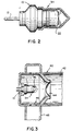
- the projectile 22 is directly attached to the squib 10, as shown in Fig. 2, forming an integral projectile squib 34. Movement of the projectile 22 in the direction indicated by the arrows 36 and 38 in Fig. 1 brings the edge 24 in covering relation to the locking ring 14 and the conically reduced internal portion 28 into engagement with the adjacent edge of the locking ring 14. Forcing the projectile 22 against the squib 10 causes the internal portion 28 to slip over the locking ring 14 and snap into place with the edge 24 and internal portion 28 in adjacent covering relation to the portion 18 and the space 20, respectively, on the squib 10, and the locking feature 32 in snapped-on locking position against the edge of the locking ring 14 that is adjacent the space 20.
- FIG. 3 shows schematically an inflation system utilizing the integral projectile squib improvement of the present invention.
- An inflator body 40 which is fragmentarily illustrated, defines a generally cylindrical chamber 42.
- the chamber 42 is filled with an inert gas such as argon under pressure.
- An actuator assembly for the inflator system consists of an integral projectile squib 34, according to the invention, comprising a squib 10 and an attached projectile 22. Between the integral projectile squib 34 and the cylindrical chamber 42 containing the pressurized gas is a burst disk 44 which seals the chamber 42.
- the projectile 22 is attached to the squib 10 prior to assembly of the integral projectile squib 34 into the inflator body 40. At the time of actuation of the squib 10, the expanding gas from the squib 10 forces the projectile 22 to overcome the locking force of the snap-on locking feature 32. This results in the projectile 22 being propelled in the desired direction to rupture the burst disk 44.
- ports 46 In the wall of the portion of the inflator body 40 that is sealed from the chamber 40 by the burst disk 44 and which contains the integral projectile squib 34, there are provided four ports 46.
- the outlet conduit 48 is in communication with an air bag (not shown) that is to be inflated.
- the stored gas under pressure in the chamber 42 immediately flows out of the ports 46 into the outlet conduit 48 and through the latter into an air bag (not shown) to be inflated.
- the prior art squibs and initiators do not use an integral projectile. They employ a separate projectile that is mechanically fastened to a third member to which the squib is also fastened. This invention does not require a third member for attachment, thus simplifying and reducing the cost of construction.
- the snap-on method of attachment of the projectile 22 to the squib 10 utilized according to the invention permits adequate retention of the projectile 22 under all severe drop and vibration environments while allowing the projectile 22 to break free when the squib 10 is activated.
- the novelty of the invention is distinguished by the ease with which the projectile 22 is attached to the body of the squib 10.
- a simple snap-on feature is provided for so that the projectile 22 may be attached to the body of the squib 10 at almost any point in time prior to installation of the integrated projectile squib 34 into the inflator.
- the advantage of this feature is that the projectile 22 does not have to be installed until immediately prior to installing the squib 10 into the air bag inflator.
- a safety hazard would exist if the projectile 22 were to be installed at the time of squib manufacture. This feature makes transport and handling of the squib 10 without the projectile 22 attached much easier. By making provision to attach the projectile 22 to the squib 10 just prior to installation in the inflator, the safety hazard is practically eliminated.
Landscapes
- Physics & Mathematics (AREA)
- Fluid Mechanics (AREA)
- Engineering & Computer Science (AREA)
- Mechanical Engineering (AREA)
- Air Bags (AREA)
Applications Claiming Priority (2)
| Application Number | Priority Date | Filing Date | Title |
|---|---|---|---|
| US08/660,646 US5622381A (en) | 1996-06-07 | 1996-06-07 | Integral projectile squid for air bag inflators |
| US660646 | 1996-06-07 |
Publications (3)
| Publication Number | Publication Date |
|---|---|
| EP0811533A2 true EP0811533A2 (fr) | 1997-12-10 |
| EP0811533A3 EP0811533A3 (fr) | 1998-09-09 |
| EP0811533B1 EP0811533B1 (fr) | 2002-04-10 |
Family
ID=24650384
Family Applications (1)
| Application Number | Title | Priority Date | Filing Date |
|---|---|---|---|
| EP97303869A Expired - Lifetime EP0811533B1 (fr) | 1996-06-07 | 1997-06-05 | Capsule détonante et projectile intégré pour générateur de gaz d'un airbag |
Country Status (4)
| Country | Link |
|---|---|
| US (1) | US5622381A (fr) |
| EP (1) | EP0811533B1 (fr) |
| JP (1) | JP3044097U (fr) |
| DE (1) | DE69711762T2 (fr) |
Cited By (1)
| Publication number | Priority date | Publication date | Assignee | Title |
|---|---|---|---|---|
| US20210170970A1 (en) * | 2019-12-05 | 2021-06-10 | Autoliv Asp, Inc. | Actuator devices and assemblies for automotive safety devices |
Families Citing this family (10)
| Publication number | Priority date | Publication date | Assignee | Title |
|---|---|---|---|---|
| US6295935B1 (en) | 1998-04-27 | 2001-10-02 | Trw Inc. | Initiator for air bag inflator |
| US6244622B1 (en) | 1998-06-16 | 2001-06-12 | Trw Inc. | Initiator for air bag inflator |
| JP2002211346A (ja) * | 2001-01-15 | 2002-07-31 | Takata Corp | インフレータ |
| US6709011B2 (en) * | 2001-02-21 | 2004-03-23 | Autoliv Asp, Inc. | Leak detection enhancing insert for an airbag inflator assembly |
| US20060103123A1 (en) * | 2004-11-12 | 2006-05-18 | Trw Vehicle Safety Systems Inc. | Inflator with shock wave focusing structure |
| US7527291B2 (en) * | 2007-09-05 | 2009-05-05 | Autoliv Asp, Inc. | Airbag inflation with sliding baffle |
| JP6888228B2 (ja) | 2017-07-20 | 2021-06-16 | 株式会社ダイセル | ガス発生器 |
| JP7324112B2 (ja) | 2019-10-08 | 2023-08-09 | 株式会社ダイセル | シートフレームインフレータおよびエアバッグ装置 |
| JP7724704B2 (ja) | 2021-12-21 | 2025-08-18 | 株式会社ダイセル | 安全装置、及び安全装置の作動方法 |
| JP7765363B2 (ja) * | 2022-08-26 | 2025-11-06 | 日本化薬株式会社 | ガス発生器 |
Family Cites Families (9)
| Publication number | Priority date | Publication date | Assignee | Title |
|---|---|---|---|---|
| US3648898A (en) * | 1971-01-06 | 1972-03-14 | Gen Motors Corp | Sensor and trigger mechanism |
| US3723205A (en) * | 1971-05-07 | 1973-03-27 | Susquehanna Corp | Gas generating composition with polyvinyl chloride binder |
| US3774807A (en) * | 1971-06-08 | 1973-11-27 | Ici America Inc | Gas-generating valve |
| BE778386R (fr) * | 1971-10-28 | 1972-05-16 | Prb Sa | Dispositif de protection d'occupant de |
| US5230531A (en) * | 1990-10-22 | 1993-07-27 | Oea, Inc. | Gas generator ignition assembly using a projectile |
| US5257819A (en) * | 1990-11-27 | 1993-11-02 | Bendix Atlantic Inflator Company | Hybrid inflator |
| US5131680A (en) * | 1991-03-19 | 1992-07-21 | Trw Vehicle Safety Systems Inc. | Inflator assembly |
| ZA948566B (en) * | 1993-11-18 | 1995-05-18 | Ici America Inc | Airbag igniter and method of manufacture |
| US5460406A (en) * | 1993-12-13 | 1995-10-24 | Trw Vehicle Safety Systems Inc. | Inflator assembly |
-
1996
- 1996-06-07 US US08/660,646 patent/US5622381A/en not_active Expired - Lifetime
-
1997
- 1997-06-05 EP EP97303869A patent/EP0811533B1/fr not_active Expired - Lifetime
- 1997-06-05 DE DE69711762T patent/DE69711762T2/de not_active Expired - Fee Related
- 1997-06-06 JP JP1997004805U patent/JP3044097U/ja not_active Expired - Lifetime
Cited By (2)
| Publication number | Priority date | Publication date | Assignee | Title |
|---|---|---|---|---|
| US20210170970A1 (en) * | 2019-12-05 | 2021-06-10 | Autoliv Asp, Inc. | Actuator devices and assemblies for automotive safety devices |
| US11912221B2 (en) * | 2019-12-05 | 2024-02-27 | Autoliv Asp, Inc. | Actuator devices and assemblies for automotive safety devices |
Also Published As
| Publication number | Publication date |
|---|---|
| US5622381A (en) | 1997-04-22 |
| EP0811533A3 (fr) | 1998-09-09 |
| EP0811533B1 (fr) | 2002-04-10 |
| DE69711762T2 (de) | 2002-11-14 |
| DE69711762D1 (de) | 2002-05-16 |
| JP3044097U (ja) | 1997-12-12 |
Similar Documents
| Publication | Publication Date | Title |
|---|---|---|
| US6454306B1 (en) | Gas generator for seat belt pretensioner | |
| EP0639483B1 (fr) | Dispositif de gonflage | |
| US5615912A (en) | Inflator for air bag | |
| US5542702A (en) | Pressurized gas inflator for vehicle occupant protection systems | |
| EP1056624B2 (fr) | Accessoire de gonflage a sortie adaptative | |
| US6062599A (en) | Air bag inflator | |
| US6168200B1 (en) | Dual level inflator | |
| US6295935B1 (en) | Initiator for air bag inflator | |
| EP2021211B1 (fr) | Dispositif gonfleur à ventilation active | |
| JP2909007B2 (ja) | 圧力センサを備えたエアバッグ膨張器 | |
| US5890735A (en) | Hybrid inflator with diffuser end translating initiator boss | |
| US5582426A (en) | Vented ignition cup in stored fluid inflator | |
| US5601308A (en) | Inflator, inflation fluid heater and assembly methods | |
| US6139055A (en) | Adaptive heated stage inflator | |
| US6168202B1 (en) | Pyrotechnic initiator with petal retainer structure | |
| US6029995A (en) | Vehicle occupant protection apparatus | |
| EP0652141A1 (fr) | Elément d'isolation pour gonfleur de coussin d'air | |
| US5622381A (en) | Integral projectile squid for air bag inflators | |
| JPH0885410A (ja) | 小型膨張器アッセンブリ | |
| US6273462B1 (en) | Air bag inflator | |
| US3966225A (en) | Inflating device with self-contained propellant gas generating cartridge | |
| US6244622B1 (en) | Initiator for air bag inflator | |
| US7108281B2 (en) | Stored gas inflator with fill valve assembly | |
| GB2247214A (en) | Vehicle airbag | |
| US6981718B2 (en) | Projectile firing barrel |
Legal Events
| Date | Code | Title | Description |
|---|---|---|---|
| PUAI | Public reference made under article 153(3) epc to a published international application that has entered the european phase |
Free format text: ORIGINAL CODE: 0009012 |
|
| AK | Designated contracting states |
Kind code of ref document: A2 Designated state(s): DE FR GB |
|
| PUAL | Search report despatched |
Free format text: ORIGINAL CODE: 0009013 |
|
| AK | Designated contracting states |
Kind code of ref document: A3 Designated state(s): AT BE CH DE DK ES FI FR GB GR IE IT LI LU MC NL PT SE |
|
| 17P | Request for examination filed |
Effective date: 19981112 |
|
| AKX | Designation fees paid |
Free format text: DE FR GB |
|
| RBV | Designated contracting states (corrected) |
Designated state(s): DE FR GB |
|
| 17Q | First examination report despatched |
Effective date: 20000608 |
|
| GRAG | Despatch of communication of intention to grant |
Free format text: ORIGINAL CODE: EPIDOS AGRA |
|
| GRAG | Despatch of communication of intention to grant |
Free format text: ORIGINAL CODE: EPIDOS AGRA |
|
| GRAH | Despatch of communication of intention to grant a patent |
Free format text: ORIGINAL CODE: EPIDOS IGRA |
|
| GRAH | Despatch of communication of intention to grant a patent |
Free format text: ORIGINAL CODE: EPIDOS IGRA |
|
| REG | Reference to a national code |
Ref country code: GB Ref legal event code: IF02 |
|
| GRAA | (expected) grant |
Free format text: ORIGINAL CODE: 0009210 |
|
| AK | Designated contracting states |
Kind code of ref document: B1 Designated state(s): DE FR GB |
|
| REF | Corresponds to: |
Ref document number: 69711762 Country of ref document: DE Date of ref document: 20020516 |
|
| ET | Fr: translation filed | ||
| PLBE | No opposition filed within time limit |
Free format text: ORIGINAL CODE: 0009261 |
|
| STAA | Information on the status of an ep patent application or granted ep patent |
Free format text: STATUS: NO OPPOSITION FILED WITHIN TIME LIMIT |
|
| 26N | No opposition filed |
Effective date: 20030113 |
|
| PGFP | Annual fee paid to national office [announced via postgrant information from national office to epo] |
Ref country code: GB Payment date: 20040602 Year of fee payment: 8 |
|
| PG25 | Lapsed in a contracting state [announced via postgrant information from national office to epo] |
Ref country code: GB Free format text: LAPSE BECAUSE OF NON-PAYMENT OF DUE FEES Effective date: 20050605 |
|
| GBPC | Gb: european patent ceased through non-payment of renewal fee |
Effective date: 20050605 |
|
| PGFP | Annual fee paid to national office [announced via postgrant information from national office to epo] |
Ref country code: DE Payment date: 20080611 Year of fee payment: 12 |
|
| PGFP | Annual fee paid to national office [announced via postgrant information from national office to epo] |
Ref country code: FR Payment date: 20080613 Year of fee payment: 12 |
|
| REG | Reference to a national code |
Ref country code: FR Ref legal event code: ST Effective date: 20100226 |
|
| PG25 | Lapsed in a contracting state [announced via postgrant information from national office to epo] |
Ref country code: FR Free format text: LAPSE BECAUSE OF NON-PAYMENT OF DUE FEES Effective date: 20090630 |
|
| PG25 | Lapsed in a contracting state [announced via postgrant information from national office to epo] |
Ref country code: DE Free format text: LAPSE BECAUSE OF NON-PAYMENT OF DUE FEES Effective date: 20100101 |