EP0811571A2 - Appareil de transport de feuilles et appareil de formation d'images - Google Patents
Appareil de transport de feuilles et appareil de formation d'images Download PDFInfo
- Publication number
- EP0811571A2 EP0811571A2 EP97109235A EP97109235A EP0811571A2 EP 0811571 A2 EP0811571 A2 EP 0811571A2 EP 97109235 A EP97109235 A EP 97109235A EP 97109235 A EP97109235 A EP 97109235A EP 0811571 A2 EP0811571 A2 EP 0811571A2
- Authority
- EP
- European Patent Office
- Prior art keywords
- gear
- sheet
- convey roller
- convey
- speed reduction
- Prior art date
- Legal status (The legal status is an assumption and is not a legal conclusion. Google has not performed a legal analysis and makes no representation as to the accuracy of the status listed.)
- Granted
Links
- 230000009467 reduction Effects 0.000 claims abstract description 74
- 238000004519 manufacturing process Methods 0.000 claims abstract description 14
- 238000007599 discharging Methods 0.000 claims description 3
- 238000009835 boiling Methods 0.000 claims description 2
- 230000004044 response Effects 0.000 claims description 2
- 230000005540 biological transmission Effects 0.000 description 6
- 230000001965 increasing effect Effects 0.000 description 6
- 230000007246 mechanism Effects 0.000 description 5
- 239000007788 liquid Substances 0.000 description 4
- 101100492406 Caenorhabditis elegans unc-85 gene Proteins 0.000 description 3
- 101100436058 Neurospora crassa (strain ATCC 24698 / 74-OR23-1A / CBS 708.71 / DSM 1257 / FGSC 987) asf-1 gene Proteins 0.000 description 3
- 230000002708 enhancing effect Effects 0.000 description 3
- 238000001514 detection method Methods 0.000 description 2
- 230000009471 action Effects 0.000 description 1
- 230000008901 benefit Effects 0.000 description 1
- 239000002131 composite material Substances 0.000 description 1
- 230000008602 contraction Effects 0.000 description 1
- 230000003247 decreasing effect Effects 0.000 description 1
- 238000000605 extraction Methods 0.000 description 1
- 238000003780 insertion Methods 0.000 description 1
- 230000037431 insertion Effects 0.000 description 1
- 230000002093 peripheral effect Effects 0.000 description 1
- 230000004304 visual acuity Effects 0.000 description 1
- 230000003313 weakening effect Effects 0.000 description 1
Images


Classifications
-
- B—PERFORMING OPERATIONS; TRANSPORTING
- B65—CONVEYING; PACKING; STORING; HANDLING THIN OR FILAMENTARY MATERIAL
- B65H—HANDLING THIN OR FILAMENTARY MATERIAL, e.g. SHEETS, WEBS, CABLES
- B65H5/00—Feeding articles separated from piles; Feeding articles to machines
- B65H5/06—Feeding articles separated from piles; Feeding articles to machines by rollers or balls, e.g. between rollers
-
- Y—GENERAL TAGGING OF NEW TECHNOLOGICAL DEVELOPMENTS; GENERAL TAGGING OF CROSS-SECTIONAL TECHNOLOGIES SPANNING OVER SEVERAL SECTIONS OF THE IPC; TECHNICAL SUBJECTS COVERED BY FORMER USPC CROSS-REFERENCE ART COLLECTIONS [XRACs] AND DIGESTS
- Y10—TECHNICAL SUBJECTS COVERED BY FORMER USPC
- Y10T—TECHNICAL SUBJECTS COVERED BY FORMER US CLASSIFICATION
- Y10T74/00—Machine element or mechanism
- Y10T74/19—Gearing
- Y10T74/19623—Backlash take-up
Definitions
- the present invention relates to a sheet conveying apparatus for conveying a sheet member such as a recording sheet and an image forming apparatus using such a sheet conveying apparatus.
- Image forming apparatuses having a pin-feed tractor have been used as output equipments for personal computers, word processors, facsimiles and the like.
- a convey roller 50 and driven pinch rollers 51a, 51b for urging a sheet against the convey roller are used as sheet convey means.
- a so-called U-turn path is provided for conveying the sheet around the convey roller 50.
- a cut sheet When a cut sheet is used as a recording medium, the cut sheet is pinched between the convey roller 50 and the pinch rollers 51a, 51b, thereby conveying the sheet by friction forces generated between these rollers.
- a continuous sheet also referred to as "fan-fold sheet” hereinafter
- pin holes formed in the fan-fold sheet are engaged by pins 52a of a pin-feed tractor 52, and the sheet is pinched between the convey roller 50 and the pinch rollers 51a, 51b, thereby conveying the sheet to a recording portion by friction forces generated between these rollers.
- the recording is effected by a recording head 53 regarding the conveyed sheet, and thereafter, the sheet is shifted upwardly and discharged out of the apparatus by a discharge roller 54a and a pinch roller 54b for urging the sheet against the discharge roller.
- a discharge roller 54a and a pinch roller 54b for urging the sheet against the discharge roller.
- an inlet opening and a discharge opening for the fan-fold sheet can be arranged at a rear portion of the apparatus, and the selection of and the switching between the fan-fold sheet and the cut sheet can be performed by manipulating a lever, in a condition that the sheets were set.
- the large diameter of the convey roller not only reduces the load resistance in the U-turn path, but also eliminates one of factors for worsening conveyance accuracy of the convey roller 50.
- the intermittent conveyance of sheet requires high accuracy; if the accuracy is poor, one-line recording area obtained by one scan of the recording head will be overlapped with the previous one-line recording area or be excessively spaced apart from the previous one-line recording area, thereby worsening the recording quality greatly.
- a rotational force of a motor is transmitted to the convey roller through gears and/or belt; in order to provide predetermined torque of the convey roller, the drive force is transmitted with speed reduction.
- the most preferential factor for giving the influence upon the sheet conveyance accuracy is eccentricity of drive force transmitting members (such as gears, belt and the like) and eccentricity of the convey roller. In order to minimize the influence of such eccentricity, various efforts for improving the accuracy of such elements have been tried.
- the present invention intends to eliminate the above-mentioned conventional drawbacks, and has an object to provide a sheet conveying apparatus and an image forming apparatus, which can handle several kinds of sheets by suppressing the influence of eccentricity of sheet conveying members and speed reduction members, and in which, even when a speed reduction ratio of a rotational force of a drive source is increased, the conveyance accuracy can be maintained.
- a sheet conveying apparatus comprises a convey member for applying a conveying force to a sheet, a drive source for driving the convey member, and a drive transmitting means for transmitting a drive force, with multi-stages, from a first drive transmitting member attached to the drive source to a second drive transmitting member attached to the convey member through one or more speed reduction members.
- first drive transmitting member, second drive transmitting member and speed reduction members manufacturing accuracy of the speed reduction member disposed at a front stage of the second drive transmitting member is greater than manufacturing accuracies of the other members.
- the speed reduction member disposed at the front stage of the second drive transmitting member has a speed reduction ratio wherein such speed reduction member is rotated by integral number, the influence of the eccentricity can be cancelled, thereby achieving high accurate conveyance.
- a cut sheet such as a plain sheet, a post card and the like, and a continuous sheet such as a fan-fold sheet can be conveyed. That is to say, when a cut sheet is used, normally, the sheet is supplied by using an ASF (auto sheet feeder) 1 or by manual sheet insertion.
- ASF auto sheet feeder
- the ASF 1 comprises two bins 1a1, 1a2 so that two kinds of cut sheets having different size can be simultaneously set and one of such cut sheets can be selected by an operator.
- Sheet supply mechanisms of bins 1a1, 1a2 are the same as each other. That is to say, the cut sheets (not shown in Fig. 1) stacked on pressure plates 1b1, 1b2 are separated and supplied one by one, by pick-up rollers 1d1, 1d2 against which the sheets are urged by urging forces of springs 1c1, 1c2.
- a pinch roller 4 held by a pinch roller folder 3 is urged against a convey roller (sheet convey member) 6 by a pinch roller spring 5.
- an auxiliary roller 7 mounted on the pinch roller holder 3 for up-and-down movement is urged against the convey roller by auxiliary roller spring 8 provided on the pinch roller holder 3.
- a needle roller 9 is held by a needle roller holder 10 and is urged against the convey roller 6 by a needle roller spring 11.
- the needle roller spring 11 is flexed by a first projection 12a of a release shaft 12, so that an urging force is generated by a spring elastic force around a support point 13.
- the cut sheet is subjected to a conveying force and is conveyed between an ink jet head (image forming means) 14 and a platen 15.
- This conveyance is intermittently effected when the ink jet head performs one scan, and an intermittent convey amount corresponds to a length of an array of ink discharge openings of the ink jet head 14 in a cut sheet conveying direction.
- an ink jet recording system of serial type in which the recording is effected by reciprocally shifting an ink jet head in a direction perpendicular to a sheet conveying direction is used as the image forming means.
- the ink jet head 14 includes fine liquid discharge openings (orifices), liquid passages, energy acting portions disposed in the liquid passages, and energy generating means for generating energy acting on the liquid disposed at the energy acting portions.
- the head 14 performs the recording by energizing an electrical/thermal converter in response to a record signal and by discharging ink from the discharge opening due to growth and contraction of a bubble generated in the ink by film-boiling caused by thermal energy.
- the cut sheet on which the recording was performed by alternately effecting the intermittent sheet conveyance and the ink discharge from the ink jet head 14 is successively conveyed upwardly of the apparatus by a gap roller 16, discharge roller 17 and driven spur wheels 16a, 17a for urging the sheet against the rollers 16, 17, and is discharged by spur wheels 17b.
- the each spur wheel has small contact area with the sheet so that, even when the spur wheel is contacted with the imaged surface of the sheet, the image formed on the sheet is not distorted by the spur wheel.
- a pin-feed tractor 27 is disposed below the ASF 1.
- a continuous sheet can be conveyed to the convey roller 6 by the pin-feed tractor, so that the recording can be effected on the continuous sheet.
- a drive transmitting mechanism including the convey roller 6 and the like of the image forming apparatus will be explained.
- a driving force of an LF (line feed) motor (drive source) 18 can be transmitted to the convey roller 6, gap roller 16 and discharge roller 17.
- the convey roller 6 is rotated by transmitting the driving force to a convey roller gear (second drive transmitting member) 22 secured to a rotary shaft of the convey roller 6, through a drive transmitting means comprised of a gear train including an LF motor gear (first drive transmitting member) 19 attached to the motor 18, a speed reduction gear (speed reduction member) 20 and an LF speed reduction gear 21.
- the gap roller 16 is rotated by transmitting the driving force to a gap roller gear 25 secured to a rotary shaft of the gap roller 16, through a drive transmitting means comprised of a gear train including the LF motor gear 19, speed reduction gear 20 and discharge speed reduction gear 24.
- the discharge roller 17 is rotated by transmitting the driving force to a discharge roller gear 26 secured to a rotary shaft of the discharge roller 17, through the LF motor gear 19, speed reduction gear 20 and discharge speed reduction gear 24.
- the driving force of the LF motor 18 is transmitted to the LF motor gear 19, speed reduction gear 20 and LF speed reduction gear 21.
- the LF speed reduction gear 21 is disengaged from a clutch gear 28, the driving force is not transmitted to the pin-feed tractor 27. That is to say, although the clutch gear 28 is biased toward a frame 30 (i.e., toward a side where the clutch gear is engaged by the LF speed reduction gear 21), as shown in Fig.
- the clutch gear 28 is pivotally connected to an arm portion 2b of the release lever 2 through a connection portion 31a and is normally disengaged from the LF speed reduction gear 21 in opposition to the biasing force by a cam portion 31b of a slide cam 31 driven by the rotation of the release cam 2.
- a step angle of the LF motor 18 becomes 7.5 degrees and a recording width obtained by one scan of the ink jet head 14, i.e., a width of an array of discharge openings becomes 1/3 inch.
- the resolving power of the ink jet head 14 is 1/360 inch, and the cut sheet can be conveyed by 1/360 inch by one step of the LF motor 18.
- the step number n becomes 120.
- the speed reduction ratio (1/36) is obtained by three stages (2/5 ⁇ 1/3 ⁇ 5/24), and, when the LF motor 18 is rotated by 2.5 revolutions, the speed reduction gear 20 is rotated by one revolution.
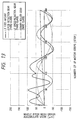
- gears of third class are used as the above-mentioned gears, and, it is assumed that the eccentricity of gears becomes a sine wave and the eccentric amounts of the gears are equal to whole pitch mesh error.
- the error of the LF feed amount per each step of the LF motor 18 can be reduced, for example, by changing the class of the whole pitch mesh error of the LF speed reduction gear 21 (speed reduction member disposed at the front stage of the convey roller gear 22) having the greatest influence of eccentricity to first class.
- the cost can be suppressed and the conveyance accuracy can be improved by enhancing the manufacturing accuracy of the LF speed reduction gear (disposed at the front stage of the convey roller gear 22 attached to the convey roller 6) having the greatest influence of eccentricity (i.e., only by enhancing the manufacturing accuracy of the gear by which the influence of eccentricity can be reduced most effectively).
- the speed reduction ratio is selected so that the speed reduction gear 20 is rotated by just one revolution when the cut sheet is conveyed by the amount corresponding to one scan, the influence of eccentricity of the LF motor gear 19 and the speed reduction gear 20 is further reduced.
- the variation in center-to-center distance when disengaging the LF speed reduction gear 21 and the convey roller gear 22 meshed with each other from the conveying apparatus and rotating without any backlash with urging one of them to the other is, smaller than the variation in center-to-center distance when disengaging the LF motor gear 19 and the speed reduction gear 20 meshed with each other from the conveying apparatus and rotating without any backlash with urging one of them to the other.
- Backlash means "play on pitch circles of a pair of gears meshed with each other" (JISB-1703).
- JISB-1703 Joint Industrial Standard 1703
- the backlash in a mechanism, when a center-to-center distance of gears (even having high accuracy) is set to be greater, the backlash is increased, thereby worsening the conveyance accuracy.
- the backlash is determined by accuracy of the gears and the center-to-center distance of the meshed gears.
- the accuracy (class) of the gears and the center-to-center distance of the meshed gears are selected so that the backlash between the convey roller gear 22 and the front stage LF speed reduction gear 21 or the backlash between the LF speed reduction gear 21 and the front stage speed reduction gear 20 becomes smaller than the backlash between the further front stage gears (LF motor gear 19 and the speed reduction gear 20).
- the LF speed reduction gear 21 and the speed reduction gear 20 each comprises two different diameter gear portions secured to a common shaft.
- a gear portion of the LF speed reduction gear 21 meshed with the convey roller gear 22 is referred to as a first gear 21a
- a gear portion meshed with the speed reduction gear 20 is referred to as a second gear 21b.
- a gear portion of the speed reduction gear 20 meshed with the second gear is referred to as a third gear 20a
- a gear portion meshed with the LF motor gear is referred to as a fourth gear 20b.
- the variation in the center-to-center distance when disengaging the convey roller gear 22 and the first gear 21a meshed with each other from the conveying apparatus without any backlash with urging one of them to the other and rotating becomes smaller than the variation in the center-to-center distance when disengaging the fourth gear 20b and the LF motor gear 19 meshed with each other from the conveying apparatus without any backlash with urging one of them to the other and rotating.
- the variation in the center-to-center distance when disengaging the second gear 21b and the third gear 20a meshed with each other from the conveying apparatus without any backlash with urging one of them to the other and rotating is preferably equal to the variation in the center-to-center distance when the convey roller gear 22 and the first gear 21a meshed with each other without any backlash are rotated, but may be equal to the variation in the center-to-center distance when the fourth gear 20b and the LF motor gear 19 meshed with each other without any backlash are rotated.
- the accuracy (class) of the gears and the center-to-center distance of the meshed gears are selected so that the backlash between the convey roller gear 22 and the front stage first gear 21a becomes smaller than the backlash between the front stage gears (fourth gear 20b and LF motor gear 19).
- the backlash between the second gear 21b and the front stage third gear 20a is preferably equal to the backlash between the convey roller gear 22 and the front stage first gear 21a.
- the pinch roller holder 3 has a pivot center disposed on the needle roller holder 10, and the auxiliary roller 7 held by the pinch roller holder 3 for up-and-down movement tries to separate from the convey roller 6, but cannot be separated from the convey roller by the presence of the auxiliary roller spring 8, thereby merely weakening the conveying force to the convey roller 6.
- the urging of the first projection 12a against the needle roller spring 11 is released, thereby reducing the urging force between the needle roller 9 and the convey roller 6.
- the driving force of the LF motor 18 in the continuous sheet selection condition is transmitted to the convey roller 6, gap roller 16, discharge roller 17 and pin-feed tractor 27.
- the drive transmission to the convey roller 6, gap roller 16 and discharge roller 17 is the same as above-mentioned cut sheet selection condition.
- the driving force to the pin-feed tractor 27 is transmitted to a tractor gear 27b secured to a tractor shaft 27a through a gear train including the LF motor gear 19, speed reduction gear 20, LF speed reduction gear 21 and clutch gear 28, thereby rotating the tractor shaft 27a. That is to say, although the clutch gear 28 is biased toward the frame 30 by the clutch spring 29, in the continuous sheet selection condition, the clutch gear 28 is connected to the tractor gear 27b by the cam portion 31c of the slide cam 31. At the same time, as shown in Fig. 6, a side portion of the slide cam 31 acts on a tractor detection sensor 33, thereby changing cut sheet mode to the continuous sheet mode electrically.
- the drive transmitting means is not limited to the gears, but may include a belt.
- the convey roller is used as the convey member for conveying the sheet
- the convey member is not limited to the roller, but may comprise a belt.
- the ink jet recording system is used as the image forming means was explained, for example, a wire dot recording system, a heat sensitive recording system or a heat transfer recording system may be used, so long as the sheet is conveyed and the recording is effected by scanning a recording head in a direction different from a sheet conveying direction.
- the ink jet head used in the illustrated embodiment includes heat generating elements disposed in nozzles for injecting ink, so that the ink droplet is discharged from the nozzle by expanding a bubble generated in the ink by thermal energy emitted from the heat generating element.
- the sheet conveying apparatus is used with the image forming apparatus, so long as the sheet conveying mechanism for transmitting the driving force from the drive source to the convey member with plural stages upon conveyance of the sheet by means of the convey member is used, the sheet conveying apparatus can be applied to an original reading apparatus, for example.
- the cost can be suppressed and conveyance accuracy can be improved by enhancing the manufacturing accuracy of the single speed reduction member by which influence of eccentricity is reduced most effectively.
- good recording accuracy can be obtained.
- the influence of eccentricity can be cancelled, thereby achieving high accurate conveyance.
- the present invention provides a sheet conveying apparatus for conveying a sheet comprising a convey member for applying a conveying force to a sheet, a drive source for driving the convey member, and a drive transmitting means for transmitting a drive force from a first drive transmitting member attached to the drive source to a second drive transmitting member attached to the convey member through one or more speed reduction members stepwisely.
- a first drive transmitting member, second drive transmitting member and speed reduction members manufacturing accuracy of the speed reduction member disposed at a front stage of the second drive transmitting member is greater than manufacturing accuracies of the other members.
Landscapes
- Engineering & Computer Science (AREA)
- Mechanical Engineering (AREA)
- Delivering By Means Of Belts And Rollers (AREA)
- Advancing Webs (AREA)
- Gear Transmission (AREA)
Applications Claiming Priority (6)
| Application Number | Priority Date | Filing Date | Title |
|---|---|---|---|
| JP145786/96 | 1996-06-07 | ||
| JP14578696 | 1996-06-07 | ||
| JP14578696 | 1996-06-07 | ||
| JP144931/97 | 1997-06-03 | ||
| JP9144931A JPH1087109A (ja) | 1996-06-07 | 1997-06-03 | シート搬送装置及び画像形成装置 |
| JP14493197 | 1997-06-03 |
Publications (3)
| Publication Number | Publication Date |
|---|---|
| EP0811571A2 true EP0811571A2 (fr) | 1997-12-10 |
| EP0811571A3 EP0811571A3 (fr) | 1998-09-16 |
| EP0811571B1 EP0811571B1 (fr) | 2003-04-23 |
Family
ID=26476200
Family Applications (1)
| Application Number | Title | Priority Date | Filing Date |
|---|---|---|---|
| EP97109235A Expired - Lifetime EP0811571B1 (fr) | 1996-06-07 | 1997-06-06 | Appareil de transport de feuilles et appareil de formation d'images |
Country Status (4)
| Country | Link |
|---|---|
| US (1) | US5902058A (fr) |
| EP (1) | EP0811571B1 (fr) |
| JP (1) | JPH1087109A (fr) |
| DE (1) | DE69721128T2 (fr) |
Families Citing this family (9)
| Publication number | Priority date | Publication date | Assignee | Title |
|---|---|---|---|---|
| US6179285B1 (en) * | 1999-01-19 | 2001-01-30 | Xerox Corporation | Media transport assembly incorporating vacuum grooves to flatten sheet |
| US7046380B2 (en) * | 2000-02-22 | 2006-05-16 | Canon Kabushiki Kaisha | Recording apparatus with feed control based on leading end margin amount |
| US7165765B2 (en) * | 2002-06-07 | 2007-01-23 | Canon Kabushiki Kaisha | Sheet feeding apparatus and recording apparatus |
| KR20050061771A (ko) * | 2003-12-18 | 2005-06-23 | 삼성전자주식회사 | 화상형성장치의 용지 이송장치 |
| JP4137008B2 (ja) | 2004-06-04 | 2008-08-20 | キヤノン株式会社 | 記録装置 |
| JP4347157B2 (ja) * | 2004-07-30 | 2009-10-21 | キヤノン株式会社 | インクジェット記録装置 |
| JP2006035802A (ja) * | 2004-07-30 | 2006-02-09 | Canon Inc | 記録装置 |
| TW200806495A (en) * | 2006-07-17 | 2008-02-01 | Asia Optical Co Inc | Automatic paper feeder capable of eliminating paper jammed |
| JP2017026094A (ja) * | 2015-07-27 | 2017-02-02 | 京セラドキュメントソリューションズ株式会社 | 駆動装置及び該駆動装置を備えた画像形成装置 |
Family Cites Families (10)
| Publication number | Priority date | Publication date | Assignee | Title |
|---|---|---|---|---|
| JPS60161083A (ja) * | 1984-01-30 | 1985-08-22 | 三菱電機株式会社 | ア−ク溶接ロボツトの旋回軸バツクラツシユ補正装置 |
| JPS61189967A (ja) * | 1985-02-20 | 1986-08-23 | Canon Inc | 紙送り機構 |
| JPH02208071A (ja) * | 1989-02-07 | 1990-08-17 | Fujitsu Ltd | プリンタのプラテン駆動装置 |
| JPH0323966A (ja) * | 1989-06-21 | 1991-01-31 | Brother Ind Ltd | 紙送り装置 |
| JPH0423664A (ja) * | 1990-05-18 | 1992-01-28 | Fujitsu General Ltd | 歯車送り装置 |
| US5141346A (en) * | 1990-06-28 | 1992-08-25 | Brother Kogyo Kabushiki Kaisha | Sheet feeder having automatic cut-sheet feed, continuous-form feed, and manual sheet insertion modes |
| JP2959259B2 (ja) * | 1991-05-27 | 1999-10-06 | セイコーエプソン株式会社 | 印字装置 |
| JPH05124276A (ja) * | 1991-10-31 | 1993-05-21 | Brother Ind Ltd | 印字装置 |
| DE4207953C2 (de) * | 1992-03-10 | 1994-11-24 | Mannesmann Ag | Drucker mit einem Antrieb für den positionsgenauen Vorschub eines Aufzeichnungsträgers in Form eines Einzelblattes oder einer Endlosbahn |
| JP3104936B2 (ja) * | 1992-09-10 | 2000-10-30 | 株式会社日立製作所 | コンベアの駆動装置 |
-
1997
- 1997-06-03 JP JP9144931A patent/JPH1087109A/ja active Pending
- 1997-06-05 US US08/869,923 patent/US5902058A/en not_active Expired - Lifetime
- 1997-06-06 EP EP97109235A patent/EP0811571B1/fr not_active Expired - Lifetime
- 1997-06-06 DE DE69721128T patent/DE69721128T2/de not_active Expired - Lifetime
Also Published As
| Publication number | Publication date |
|---|---|
| DE69721128D1 (de) | 2003-05-28 |
| US5902058A (en) | 1999-05-11 |
| JPH1087109A (ja) | 1998-04-07 |
| EP0811571A3 (fr) | 1998-09-16 |
| DE69721128T2 (de) | 2004-01-29 |
| EP0811571B1 (fr) | 2003-04-23 |
Similar Documents
| Publication | Publication Date | Title |
|---|---|---|
| US5793399A (en) | Sheet supplying apparatus | |
| EP0658433B1 (fr) | Appareil pour l'alimentation et la correction du désalignement du papier | |
| JP3577013B2 (ja) | 排出ローラの駆動方法、および記録装置 | |
| US5738453A (en) | Sheet supplying apparatus | |
| US5506606A (en) | Record apparatus | |
| US5674019A (en) | Image forming apparatus, and method thereof | |
| EP0811571B1 (fr) | Appareil de transport de feuilles et appareil de formation d'images | |
| JPH06345284A (ja) | ベルト搬送装置及びこれを用いた中間転写型インクジェット記録装置 | |
| EP1870248A2 (fr) | Imprimante et procédé d'impression | |
| US5899613A (en) | Image recording apparatus having conveying means for both continuous sheet and single sheet | |
| US7533878B2 (en) | Printer media transport for variable length media | |
| US6655865B2 (en) | Printing apparatus and method | |
| JP2002361958A (ja) | 記録装置および記録方法 | |
| US5951180A (en) | Printing apparatus with step-driven reversible pickup-roller | |
| US20020114655A1 (en) | Printing apparatus and method | |
| EP0661165A2 (fr) | Dispositif d'enregistrement | |
| JPH08225182A (ja) | シ−ト材搬送装置および画像形成装置 | |
| US6017160A (en) | Printer sheet feed device having controller | |
| US5018888A (en) | Paper tension adjusting device and method for a printer | |
| EP1652681B1 (fr) | Dispositif d'enregistrement d'images et dispositif de transport de feuilles | |
| US6443446B1 (en) | Media transport mechanism for information transfer devices | |
| US20230398796A1 (en) | Transport roller pair including drive roller and follower roller that transport medium held therebetween, medium transport device, and image forming apparatus | |
| JPH10310279A (ja) | 記録紙送り装置 | |
| EP1759863A1 (fr) | Imprimante | |
| JPH10250174A (ja) | 記録装置 |
Legal Events
| Date | Code | Title | Description |
|---|---|---|---|
| PUAI | Public reference made under article 153(3) epc to a published international application that has entered the european phase |
Free format text: ORIGINAL CODE: 0009012 |
|
| AK | Designated contracting states |
Kind code of ref document: A2 Designated state(s): DE FR GB IT |
|
| PUAL | Search report despatched |
Free format text: ORIGINAL CODE: 0009013 |
|
| AK | Designated contracting states |
Kind code of ref document: A3 Designated state(s): AT BE CH DE DK ES FI FR GB GR IE IT LI LU MC NL PT SE |
|
| 17P | Request for examination filed |
Effective date: 19990202 |
|
| AKX | Designation fees paid |
Free format text: DE FR GB IT |
|
| RBV | Designated contracting states (corrected) |
Designated state(s): DE FR GB IT |
|
| 17Q | First examination report despatched |
Effective date: 19990503 |
|
| GRAG | Despatch of communication of intention to grant |
Free format text: ORIGINAL CODE: EPIDOS AGRA |
|
| GRAG | Despatch of communication of intention to grant |
Free format text: ORIGINAL CODE: EPIDOS AGRA |
|
| GRAH | Despatch of communication of intention to grant a patent |
Free format text: ORIGINAL CODE: EPIDOS IGRA |
|
| GRAH | Despatch of communication of intention to grant a patent |
Free format text: ORIGINAL CODE: EPIDOS IGRA |
|
| GRAA | (expected) grant |
Free format text: ORIGINAL CODE: 0009210 |
|
| AK | Designated contracting states |
Designated state(s): DE FR GB IT |
|
| REG | Reference to a national code |
Ref country code: GB Ref legal event code: FG4D |
|
| REF | Corresponds to: |
Ref document number: 69721128 Country of ref document: DE Date of ref document: 20030528 Kind code of ref document: P |
|
| ET | Fr: translation filed | ||
| PLBE | No opposition filed within time limit |
Free format text: ORIGINAL CODE: 0009261 |
|
| STAA | Information on the status of an ep patent application or granted ep patent |
Free format text: STATUS: NO OPPOSITION FILED WITHIN TIME LIMIT |
|
| 26N | No opposition filed |
Effective date: 20040126 |
|
| PGFP | Annual fee paid to national office [announced via postgrant information from national office to epo] |
Ref country code: IT Payment date: 20090620 Year of fee payment: 13 |
|
| REG | Reference to a national code |
Ref country code: FR Ref legal event code: ST Effective date: 20110228 |
|
| PG25 | Lapsed in a contracting state [announced via postgrant information from national office to epo] |
Ref country code: IT Free format text: LAPSE BECAUSE OF NON-PAYMENT OF DUE FEES Effective date: 20100606 |
|
| PG25 | Lapsed in a contracting state [announced via postgrant information from national office to epo] |
Ref country code: FR Free format text: LAPSE BECAUSE OF NON-PAYMENT OF DUE FEES Effective date: 20100630 |
|
| PGFP | Annual fee paid to national office [announced via postgrant information from national office to epo] |
Ref country code: DE Payment date: 20150630 Year of fee payment: 19 Ref country code: GB Payment date: 20150626 Year of fee payment: 19 |
|
| PGFP | Annual fee paid to national office [announced via postgrant information from national office to epo] |
Ref country code: FR Payment date: 20090624 Year of fee payment: 13 |
|
| REG | Reference to a national code |
Ref country code: DE Ref legal event code: R119 Ref document number: 69721128 Country of ref document: DE |
|
| GBPC | Gb: european patent ceased through non-payment of renewal fee |
Effective date: 20160606 |
|
| PG25 | Lapsed in a contracting state [announced via postgrant information from national office to epo] |
Ref country code: DE Free format text: LAPSE BECAUSE OF NON-PAYMENT OF DUE FEES Effective date: 20170103 |
|
| PG25 | Lapsed in a contracting state [announced via postgrant information from national office to epo] |
Ref country code: GB Free format text: LAPSE BECAUSE OF NON-PAYMENT OF DUE FEES Effective date: 20160606 |