EP0811766A2 - Pompe de déplacement positif à vide - Google Patents
Pompe de déplacement positif à vide Download PDFInfo
- Publication number
- EP0811766A2 EP0811766A2 EP97108724A EP97108724A EP0811766A2 EP 0811766 A2 EP0811766 A2 EP 0811766A2 EP 97108724 A EP97108724 A EP 97108724A EP 97108724 A EP97108724 A EP 97108724A EP 0811766 A2 EP0811766 A2 EP 0811766A2
- Authority
- EP
- European Patent Office
- Prior art keywords
- pump
- section
- gas
- displacement type
- type vacuum
- Prior art date
- Legal status (The legal status is an assumption and is not a legal conclusion. Google has not performed a legal analysis and makes no representation as to the accuracy of the status listed.)
- Granted
Links
Images


Classifications
-
- F—MECHANICAL ENGINEERING; LIGHTING; HEATING; WEAPONS; BLASTING
- F04—POSITIVE - DISPLACEMENT MACHINES FOR LIQUIDS; PUMPS FOR LIQUIDS OR ELASTIC FLUIDS
- F04C—ROTARY-PISTON, OR OSCILLATING-PISTON, POSITIVE-DISPLACEMENT MACHINES FOR LIQUIDS; ROTARY-PISTON, OR OSCILLATING-PISTON, POSITIVE-DISPLACEMENT PUMPS
- F04C23/00—Combinations of two or more pumps, each being of rotary-piston or oscillating-piston type, specially adapted for elastic fluids; Pumping installations specially adapted for elastic fluids; Multi-stage pumps specially adapted for elastic fluids
- F04C23/001—Combinations of two or more pumps, each being of rotary-piston or oscillating-piston type, specially adapted for elastic fluids; Pumping installations specially adapted for elastic fluids; Multi-stage pumps specially adapted for elastic fluids of similar working principle
-
- F—MECHANICAL ENGINEERING; LIGHTING; HEATING; WEAPONS; BLASTING
- F04—POSITIVE - DISPLACEMENT MACHINES FOR LIQUIDS; PUMPS FOR LIQUIDS OR ELASTIC FLUIDS
- F04C—ROTARY-PISTON, OR OSCILLATING-PISTON, POSITIVE-DISPLACEMENT MACHINES FOR LIQUIDS; ROTARY-PISTON, OR OSCILLATING-PISTON, POSITIVE-DISPLACEMENT PUMPS
- F04C18/00—Rotary-piston pumps specially adapted for elastic fluids
- F04C18/08—Rotary-piston pumps specially adapted for elastic fluids of intermeshing-engagement type, i.e. with engagement of co-operating members similar to that of toothed gearing
- F04C18/12—Rotary-piston pumps specially adapted for elastic fluids of intermeshing-engagement type, i.e. with engagement of co-operating members similar to that of toothed gearing of other than internal-axis type
- F04C18/14—Rotary-piston pumps specially adapted for elastic fluids of intermeshing-engagement type, i.e. with engagement of co-operating members similar to that of toothed gearing of other than internal-axis type with toothed rotary pistons
- F04C18/16—Rotary-piston pumps specially adapted for elastic fluids of intermeshing-engagement type, i.e. with engagement of co-operating members similar to that of toothed gearing of other than internal-axis type with toothed rotary pistons with helical teeth, e.g. chevron-shaped, screw type
-
- F—MECHANICAL ENGINEERING; LIGHTING; HEATING; WEAPONS; BLASTING
- F04—POSITIVE - DISPLACEMENT MACHINES FOR LIQUIDS; PUMPS FOR LIQUIDS OR ELASTIC FLUIDS
- F04C—ROTARY-PISTON, OR OSCILLATING-PISTON, POSITIVE-DISPLACEMENT MACHINES FOR LIQUIDS; ROTARY-PISTON, OR OSCILLATING-PISTON, POSITIVE-DISPLACEMENT PUMPS
- F04C29/00—Component parts, details or accessories of pumps or pumping installations, not provided for in groups F04C18/00 - F04C28/00
- F04C29/0042—Driving elements, brakes, couplings, transmissions specially adapted for pumps
- F04C29/0085—Prime movers
-
- F—MECHANICAL ENGINEERING; LIGHTING; HEATING; WEAPONS; BLASTING
- F04—POSITIVE - DISPLACEMENT MACHINES FOR LIQUIDS; PUMPS FOR LIQUIDS OR ELASTIC FLUIDS
- F04C—ROTARY-PISTON, OR OSCILLATING-PISTON, POSITIVE-DISPLACEMENT MACHINES FOR LIQUIDS; ROTARY-PISTON, OR OSCILLATING-PISTON, POSITIVE-DISPLACEMENT PUMPS
- F04C2220/00—Application
- F04C2220/10—Vacuum
- F04C2220/12—Dry running
-
- F—MECHANICAL ENGINEERING; LIGHTING; HEATING; WEAPONS; BLASTING
- F04—POSITIVE - DISPLACEMENT MACHINES FOR LIQUIDS; PUMPS FOR LIQUIDS OR ELASTIC FLUIDS
- F04C—ROTARY-PISTON, OR OSCILLATING-PISTON, POSITIVE-DISPLACEMENT MACHINES FOR LIQUIDS; ROTARY-PISTON, OR OSCILLATING-PISTON, POSITIVE-DISPLACEMENT PUMPS
- F04C2240/00—Components
- F04C2240/50—Bearings
- F04C2240/51—Bearings for cantilever assemblies
Definitions
- the present invention relates in general to vacuum pumps for use, for example, in semiconductor industries, and particularly relates to a displacement type dry pump which can exhaust a gas from an atmospheric pressure, and can attain a vacuum in a range from 10 -4 torr to several torr.
- Vacuum pumps used in semiconductor industries to exhaust process gases from a processing chamber must be dry types which do not rely on the use of oil in their internal passages so as to maintain a clean processing environment.
- the vacuum pumps may be displacement pumps which have dual shafts, and the rotor configuration can be either a root type or a screw type.
- FIG 8 shows one type of screw type vacuum pump having dual shafts.
- the pump comprises a casing 100 which houses two parallel shafts 101, 102, which have screw rotors 103, 104 having screw threads for mating with each other.
- One of the shaft 101 is rotated by a motor 105, and the rotating force is transmitted to the other shaft 102 through a gear 106 attached to the opposite end of the shaft 101.
- a gas trapped in the space formed by the casing 100 and screw rotors 103, 104 is transported in the axial direction to be exhausted by mating screw threads.
- Such a pump is simple in structure and its basic function is to move a certain volume of gas, which is trapped in the casing, by the rotary action of the rotors 103, 104, but it does not have a gas compressing function, therefore, if the exhausting process relies only on a single-stage pump, it presents a problem that the power consumption per unit volume of discharged gas is rather high.
- pumps of different exhausting capacities may be combined in such a way that a large capacity pump is placed on the gas admittance side (at low pressure side) and a smaller capacity pump on the gas discharge side (at atmospheric pressure side).
- a consideration may be given to two kinds of systems.
- One system is provided with a combination of two separate pumps which have driving mechanism in each pump.
- the other system is a combination of two screw rotors which are attached on the common drive shaft.
- Another object of the present invention is to provide a dry type pump to enable to select pump operating parameters such as operating temperatures and discharge volumes, when reaction products are deposited during exhausting a process gas, or on the applicability of utility facilities such as cooling water. Such a pump would provide small compact size, long service life and lower energy consumption.
- a displacement type vacuum pump having a pair of parallel drive shafts rotating in opposite directions within a casing, and a pair of screw rotors having screw threads thereon mounted on each of said drive shafts, said screw threads mating with each other for transporting and exhausting a gas trapped in a space formed by the casing, comprising: first pump section having a pair of drive shafts rotating in opposite directions within first casing, and a pair of screw rotors having screw threads thereon mounted on each of the drive shafts, the screw threads mating with each other for transporting and exhausting a gas trapped in the first casing; second pump section having a pair of drive shafts rotating in opposite directions within second casing, and a pair of screw rotors having screw threads thereon mounted on each of said drive shafts, the screw threads mating with each other for transporting and exhausting a gas trapped in the second casing; and a motor section mounted between said first pump section and said second pump section for driving said pair of drive shaft
- both screw rotors of both pump sections can be made short length enabling a cantilever support.
- This structure of the pump makes the dual shaft screw type vacuum pump simple and promotes easy maintenance.
- This structure also permits support bearings to be placed on the inside region of the pump, thus minimizing volatile components in the lubricating grease to back stream into the vacuum side of the pump. Also, the bearings are placed away from the discharge side of the pump, especially from the second pump section, so as to keep their temperature low.
- An aspect of the present invention is to provide a displacement type vacuum pump that the drive shaft is supported by bearings mounted between the motor section and the pump section for supporting the screw rotor in a contileveler manner, according maintainability of the pump is improved.
- Another aspect of the present invention is to provide a displacement type vacuum pump that the first pump section has an exhaust capacity which is higher than an exhaust capacity of the second pump section, accordingly, in a low pressure range of gas admittance pressure, the power consumption per unit volume of exhausted gas becomes low.
- Another aspect of the present invention is to provide a displacement type vacuum pump that the displacement type vacuum pump does not use a lubricating oil for lubricating the bearings, accordingly, potential sources of contamination are reduced.
- Another aspect of the present invention is to provide a displacement type vacuum pump that a pair of drive shafts are magnetically coupled and rotated synchronously with each other.
- Another aspect of the present invention is to provide a displacement type vacuum pump that a gas flow passage is provided inside of the motor section for transporting an exhausted gas from the first pump section to the second pump section. Accordingly, the pump is made compact and also offers an advantage of enabling to provide heat generated in the windings to the gas passage.
- Another aspect of the present invention is to provide a displacement type vacuum pump that a gas flow passage is provided outside of the motor section for transporting an exhausted gas from the first pump section to the second pump section. Accordingly, control of the temperature of the gas passage and maintenance work are facilitated.
- Another aspect of the present invention is to provide a displacement type vacuum pump that a bypass passage is provided for relieving a pressure rise by directing a gas from an inlet of the second pump section to a gas discharge port thereof when an inlet pressure of the second pump section exceeds an outlet pressure thereof. Accordingly, when operating in a high pressure range of the gas admittance pressure, it enables to avoid increasing the internal pressure in the pump thereby enabling to reduce the required torque on the rotors.
- Another aspect of the present invention is to provide a displacement type vacuum pump that a control means is provided therewith for reducing rotation speed of the drive shafts so as to keep power consumption substantially constant, when pressure becomes too high to exceed torque ratings of the motor section. Accordingly, it enables to maintain the power consumption substantially constant during the startup and steady state phases of the operation of the pump, and avoiding any problems introduced by excessive current flow through the windings.
- Figure 1 is a horizontal cross sectional view of a first embodiment of the vacuum pump of the present invention.
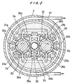
- Figure 2 is a cross sectional view seen at a section along the arrow A in Figure 1.
- Figure 3 is a block diagram of the electrical circuit of the vacuum pump.
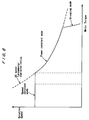
- Figure 4 is a graph showing the torque characteristics at different degrees of vacuum generated by the vacuum pump.
- Figure 5 is a graph showing the exhausting velocity, rotation speed, the power consumption of the vacuum pump.
- Figure 6 is a schematic illustration of the operating range of the vacuum pump.
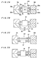
- FIGS. 7A ⁇ 7D are schematic representation of other embodiments of the vacuum pump of the present invention.
- Figure 8 is a cross sectional view of a conventional screw type vacuum pump.
- the vacuum pump 1 comprises a pair of parallel shafts 2a, 2b which are disposed within a casing with three separate chambers provided along the longitudinal axis.
- a cylindrical shaped motor casing 3 houses a motor chamber 4.
- a first pumping chamber 7, and a second pumping chamber 8 confined by the corresponding pump casings 5, 6, are disposed respectively.
- the motorside separation rings 9, 10 are provided therebetween for isolating the pumping chambers 7, 8 from the motor chamber 4.
- the ends of the pump casings 5, 6 are closed with end covers 13, 14 having a (process) gas admittance port 11 or a (process) gas discharge port 12 provided in the central region.
- the shafts 2a, 2b passes through the three chambers 4, 5 and 6, as described above, and is freely rotatably supported by a pair of bearings (ball bearings) 15a, 15b on the admittance-side and a pair of bearings (ball bearings) 16a, 16b on the discharge-side, installed in the corresponding motorside separation rings 9, 10.
- Each shaft 2a, 2b is supported at one end, in a so-called cantilever style, and the opposite ends are freely rotatably disposed within the pump chambers 7, 8.
- Each pair of bearings, 15a, 15b and 16a, 16b are lubricated with grease, and are inserted into the bearing housings 17, 18 which are firmly disposed in the motor-side separation rings 9, 10 of the respective chambers.
- Magnets 20a, 20b are attached on the outer peripheries of each of the shafts 2a, 2b, and in this case, the magnets 20a, 20b is provided with alternating four N and S poles, as shown in Figure 2.
- the iron core stators 21a ⁇ 26b surrounding the magnetic rotors 20a, 20b are arranged so as to electrically connect at the plane symmetry positions of the two shafts. Thereby it is provided with a synchronous motor M having dual shafts which can rotate synchronously with each other, regardless of whether the motor is powered or not powered.
- the motor M is a brushless direct current motor, and to operate this motor M, the a.c. supply power is first rectified, as shown in the block diagram of the electrical circuit given in Figure 3, and the supply of power to the motor windings is alternated by the switching circuit 41, depending on the angular position of the rotors 20a, 20b. According to this arrangement, the two shafts 2a, 2b can rotate in synchronization but in the opposite directions.
- a coolant passage 27 is provided for flowing cooling water in the interior of the motor casing 3, and the water supply pipe communicating with this passage is provided with a flow regulator valve. Almost all of the power input into the vacuum pump is converted into heat generated by the pump motor in compressing the process gas. The torque required to compress the gas is dependent on the pressure difference, but the output torque of the motor is relatively independent of the rotational speed, and so, the heat generated by the pump corresponds to the rotational speed of the pump. Therefore, it is possible to control the temperature of the various sections of the pump to some degree by controlling the rotational speed and the flow rate of the cooling water.
- the interior spaces of the pumping chambers 7, 8 of the respective shafts 2a, 2b are occupied by screw rotors 28a, 28b and 29a, 29b having threads 30a, 30b (in this case, trapezoidal cross section) machined on their outer peripheries, and are attached to the shaft 2a, 2b by wedge rings 40 and bolts 41.
- the threads cut on the rotors themselves are coupled with each other while maintaining minute clearance therebetween, and the outer peripheries of the rotors also maintain some clearance to the pump casings 5, 6.
- the screw rotors 28a, 28b, 29a, 29b and the pump casings 5, 6 constitute a displacement pump.
- the shape and size of the screw rotors 30a, 30b and 28a ⁇ 29b for the first pump section 5A and the second pump section 6A are determined as follows. Although the inter-axial distances of the shaft 2a, 2b in the first pump section 5A and in the second pump section 6A are the same, the exhaust volume from the first pump section 5A is made greater by an amount per one rotation than the second pump section 6A (in this case, 4:1), by selecting the thread pitch, outer diameter and the root diameter appropriately.
- the gas outlet port 31 of the first pump section 5A and the gas inlet port 33 of the second pump section 6A are communicated with the gas transport passage 32 provided through the interior section of the motor stator.
- the gas delivery passage 32 is located close to the motor windings 34, and is therefore warmed by the heat given off by the windings while it is operating.
- a bypass passage 36 having a one-way valve 35 is provided between the inlet port 33 of the second pump section 6A and the discharge port 12, and the one-way valve 35 is set to open when the pressure in the gas inlet port 33 becomes higher than that in the second discharge port 12, by a certain pressure value.
- the electrical control circuit comprises, a rectifying circuit 40, a switching circuit 41, a power control section 42 for controlling the switching circuit 41, and the power control section 42 alternately governing the rotation speed reference value and the current reference value in accordance with the output signals from the position/rotation sensors 43 provided on the motor M and from the current sensor provided on the power circuit.
- two sets of screw rotors 28a, 28b, and 29a, 29b are provided in the axial direction, so that the lengths of each rotor is shorter than the integrated type of design used in the conventional dual shaft pump shown in Figure 8.
- the design requires a total of six spirals for a set of screw rotors, by dividing the rotors into two spirals on the inlet side and four spirals on the outlet side, the length of rotors on each side (i.e. vacuum side and the pressure side) can be shortened and yet produce a given degree of vacuum.
- the short rotors, as illustrated in Figure 1 produce lesser bending moment and enable to suppress wobbling of the shaft ends to an allowable level, even when the shafts are supported at one end only.
- the advantage of the cantilever type support design is the ease of maintenance. Because the rotors 28a ⁇ 29b are supported by the bearings 15a ⁇ 16b only at an inside end and no bearings are provided at the inlet or outlet side of the pump sections, the pump can be serviced by simply removing the end covers 13, 14 and wedge ring 40 and bolts 41 to take out the screw rotors 28a ⁇ 29b. It can be seen that disassembly of the pump becomes simple and maintenance work is facilitated. Because there are no bearings on the gas admittance side to the vacuum pump 5A, it is possible to prevent the volatile components contained in bearing lubricants such as grease to back stream into the vacuum side.
- the motor driver device supplies alternating current of a given frequency to the stator coil 34, and the rotating magnetic fields of the stator rotate the pair of rotors 20a, 20b.
- the two shafts 2a, 2b are magnetically coupled to rotate in opposite directions, thus avoiding the need to differentiate the driver side from the driven side required for a mechanically coupled pump like using gears 106 as shown in Figure 8. Consequently, the rotation of the rotors becomes smooth and is highly synchronized therebetween.
- the rotating shafts 2a, 2b causes the mating screw rotors 28a ⁇ 29b in the pump sections 5A, 6A to rotate, thereby transporting the gas trapped in the spaces.
- the gas enters through the admittance port 11 of the pump section 5A, and flows into the screw rotors 28a, 28b, and through the gas outlet port 31 to the gas transport passage 32, and into the inlet port of the second pump 6A from the gas transport passage 32, and is condensed and transported through the screw rotors 29a, 29b, and exhausted from the gas discharge port 12.
- the output volume from the first pump 5A is designed to be greater than that from the second pump 6A, by an amount per one rotation, and during the steady state operation, a relatively high vacuum can be achieved, without increasing the power consumption, even though this is a displacement vacuum pump.
- the pressure difference in the exhaust capacities of the two pumps 5A, 6A causes the pressure in the gas transport delivery passage 32 to be raised.
- the gas discharge pressure normally, an atmospheric pressure
- the one-way valve 35 in the bypass passage 36 opens. The gas then bypasses the second pump section 6A, thereby preventing the pressure to be raised beyond a pre-determined value. Therefore, safety is assured and the required torque for driving the first pump section 5A is significantly reduced, and the power consumption is lowered, as shown in Figure 4.
- the power control section 42 usually controls the motor M in such a way to maintain a constant rotation speed.
- a higher torque is necessary as mentioned above, and if the controller commands a constant speed, an output torque exceeding the torque rating of the motor is required.
- the controller lowers the speed of the motor, in a operation stage close to atmospheric pressure range, wherein required torque exceeds the torque rating of the motor (refer to the curves in Figure 5 and 6). Therefore, it becomes possible to operate the pump at all pressure levels under maximum torque ratings of the pump.
- rotation speed is reduced through the supply voltage control provided by the power control section 42.
- Figure 4 shows a graph of the basic performance characteristics of the first and second pump section 5A and 6A, separately and in combination with or without the bypass passage. As shown in Figure 4, it is only possible to utilize the basic performance of each motor directly in a limited range of pressures. At a constant speed of rotation, the double shaft synchronous dc motor can produce higher torque beyond the range of single pumps.
- the required torque for the pump rotor depends on the differential pressures existing between the gas admittance port 11 and the gas discharge port 12 than on the rotation speed.
- the effect of the differential pressure at the inlet/outlet of the first pump section 5A for the torque requirement is almost negligibly small, and therefore, as shown in Figure 4, the required torque is almost same as required torque by the second pump section 6A. Therefore, compared with the torque curves for single pump device, the required power per unit discharge volume to operate the double pump device becomes lower, the result is that the dual stage pump of the present invention consumes less power than the single stage pump as shown in Figure 8.
- the pressure at the gas outlet port 31 (namely, equal to gas inlet port 33 of the second pump section 6A) of the first pump section 5A is only a few torr, the temperature at the vicinity of the bearings is not highly raised by the effect of the gas compression. Therefore it allows the lubricated bearings to be operated stably without the fear of its decomposition by the temperature raise thereof.
- the exhaust gas from the first pump section 5A is transported to the inlet of the second pump section 6A through the gas transport passage 32 formed in the interior of the motor stator section.
- the gas transport passage 32 is close to the motor windings 34, and the passage is warmed by the heat generated in the windings. Therefore, those gases which produces reaction product to deposit on the internal surface of the passage at low temperature can be handled by the pump without the fear of causing their decomposition.
- the displacement pump is provided with a coolant passage 27 for flowing cold water in the motor frame 3.
- Most of the power required for operating the vacuum pump is consumed in compressing the gas, and this heat appears to raise the temperature of the pump motor.
- the pump torque is relatively independent of the rotation speed of the screw rotors but is dependent largely of the pressure difference, it is possible to control the amount of heat generation by adjusting the rotational speed of the synchronous motor. Therefore, the temperatures of various parts of the pump can be controlled to some extent by regulating the rotation speed and flow rate of the coolant.
- the present embodiment of the displacement pump enables to prolong its service life by allowing to select operational variables such as amount of coolant and rotation speed according to the features of the device fabrication process for which the pump is being used.
- Figure 7A through 7D shows various kinds of the embodiments of the present invention.
- Figure 7A is a schematic representation of the above-mentioned first embodiment which is corresponding to the pump structure of Figure 1
- Figures 7B ⁇ 7C are schematic representations of other embodiments of the displacement pump.
- the drive source is a synchronous motor located in the motor section M having dual shafts, and the gas delivery passage 32 communicating the two pump sections 5A, 6A are located in the interior of the motor section.
- Figure 7B shows the gas passage 32a, which is provided within an external piping 35, and a heater 36 may be provided as necessary to heat the external piping 35. Because it is an external connection connecting two pump sections 5A and 6A, it may be easily detached to facilitate maintenance work.
- the drive source is a regular single shaft motor M', and a gear arrangement 37 is used to transmit the rotational motion of motor M' from one shaft to the other shaft.
- a dual shaft synchronous motor M is combined with a gear arrangement 37 to further improve the synchronicity.
- one drive source is used to operate two pump sections 5A, 6A to achieve a vacuum environment efficiently and at low power consumption.
- the screw rotors 28a ⁇ 29b are supported only at one end, to present a simple construction and ease of maintenance. It should be noted that the configurations shown in Figures 7C and 7D are also compatible with either an external or internal arrangement of the gas passages 32, 32a as shown in Figures 7A and 7B.
- the embodiments of the pump are equally effective when used as a compressor by having a low pressure on the gas admittance side and a high pressure on the gas discharge side of the pump shown in the embodiments.
- the invention relates to a displacement type vacuum pump, comprising:
Landscapes
- Engineering & Computer Science (AREA)
- Mechanical Engineering (AREA)
- General Engineering & Computer Science (AREA)
- Applications Or Details Of Rotary Compressors (AREA)
Applications Claiming Priority (3)
| Application Number | Priority Date | Filing Date | Title |
|---|---|---|---|
| JP16240196A JP3432679B2 (ja) | 1996-06-03 | 1996-06-03 | 容積式真空ポンプ |
| JP162401/96 | 1996-06-03 | ||
| JP16240196 | 1996-06-03 |
Publications (4)
| Publication Number | Publication Date |
|---|---|
| EP0811766A2 true EP0811766A2 (fr) | 1997-12-10 |
| EP0811766A3 EP0811766A3 (fr) | 1999-07-28 |
| EP0811766B1 EP0811766B1 (fr) | 2004-02-11 |
| EP0811766B9 EP0811766B9 (fr) | 2004-09-15 |
Family
ID=15753915
Family Applications (1)
| Application Number | Title | Priority Date | Filing Date |
|---|---|---|---|
| EP97108724A Expired - Lifetime EP0811766B9 (fr) | 1996-06-03 | 1997-05-30 | Pompe de déplacement positif à vide |
Country Status (6)
| Country | Link |
|---|---|
| US (1) | US5846062A (fr) |
| EP (1) | EP0811766B9 (fr) |
| JP (1) | JP3432679B2 (fr) |
| KR (1) | KR100485919B1 (fr) |
| DE (1) | DE69727514T2 (fr) |
| TW (1) | TW374830B (fr) |
Cited By (11)
| Publication number | Priority date | Publication date | Assignee | Title |
|---|---|---|---|---|
| WO2001023762A1 (fr) * | 1999-09-24 | 2001-04-05 | Leybold Vakuum Gmbh | Pompe a vis, notamment pompe a vide a vis, comportant deux etages |
| EP1101942A3 (fr) * | 1999-11-17 | 2002-05-15 | Teijin Seiki Co., Ltd. | Appareil pour évacuer un système à vide |
| WO2003100258A1 (fr) * | 2002-05-29 | 2003-12-04 | Leybold Vakuum Gmbh | Pompe a vide a deux arbres |
| EP1429030A3 (fr) * | 2002-08-27 | 2004-07-14 | Sanyo Electric Co., Ltd | Compresseur rotatif multi-étages |
| KR100485919B1 (ko) * | 1996-06-03 | 2005-07-28 | 가부시키가이샤 에바라 세이사꾸쇼 | 용적형진공펌프 |
| EP1265338A3 (fr) * | 2001-06-06 | 2006-07-19 | Ebara Corporation | Pompe à vide |
| EP1217214B1 (fr) * | 2000-12-21 | 2008-08-06 | Ingersoll-Rand European Sales Limited | Ensemble moteur électrique-compresseur |
| EP2532895A1 (fr) * | 2011-06-06 | 2012-12-12 | Vacuubrand Gmbh + Co Kg | Pompe à vide avec des paliers disposés à un côté |
| CN107454926A (zh) * | 2015-02-23 | 2017-12-08 | 施蓝姆伯格技术公司 | 用于对苛刻流体加压的方法和系统 |
| GB2606223A (en) * | 2021-04-30 | 2022-11-02 | Edwards Ltd | Stator for a vacuum pump |
| US12345261B2 (en) | 2021-04-30 | 2025-07-01 | Edwards Limited | Stator for a vacuum pump |
Families Citing this family (60)
| Publication number | Priority date | Publication date | Assignee | Title |
|---|---|---|---|---|
| JP2007263121A (ja) * | 1999-11-17 | 2007-10-11 | Nabtesco Corp | 真空排気装置 |
| JP2007263122A (ja) * | 1999-11-17 | 2007-10-11 | Nabtesco Corp | 真空排気装置 |
| JP2007298043A (ja) * | 1999-11-17 | 2007-11-15 | Nabtesco Corp | 真空排気装置 |
| DE10039006A1 (de) * | 2000-08-10 | 2002-02-21 | Leybold Vakuum Gmbh | Zweiwellenvakuumpumpe |
| BE1013944A3 (nl) * | 2001-03-06 | 2003-01-14 | Atlas Copco Airpower Nv | Watergeinjecteerde schroefcompressor. |
| JP4218756B2 (ja) * | 2003-10-17 | 2009-02-04 | 株式会社荏原製作所 | 真空排気装置 |
| DE102005008887A1 (de) * | 2005-02-26 | 2006-08-31 | Leybold Vacuum Gmbh | Einwellige Vakuum-Verdränderpumpe |
| JP4673136B2 (ja) * | 2005-06-09 | 2011-04-20 | 株式会社日立産機システム | スクリュー圧縮機 |
| JP5009634B2 (ja) * | 2006-01-31 | 2012-08-22 | 株式会社荏原製作所 | 真空ポンプユニット |
| US20090288648A1 (en) * | 2008-05-21 | 2009-11-26 | Gm Global Technology Operations, Inc. | Superchargers with dual integral rotors |
| US20130343912A1 (en) * | 2011-03-11 | 2013-12-26 | Ulvac Kiko, Inc. | Vacuum pump, vacuum exhaust device, and method of operating vacuum pump |
| JP5777379B2 (ja) * | 2011-04-05 | 2015-09-09 | 株式会社日立産機システム | 空気圧縮機 |
| FR2984424B1 (fr) * | 2011-12-14 | 2018-06-01 | Danfoss Commercial Compressors | Compresseur frigorifique a spirales a vitesse variable |
| DE102011057069B4 (de) | 2011-12-27 | 2014-10-30 | Hokwang Industries Co., Ltd. | Nachfüllbare Flüssigseifen-Spendevorrichtung |
| EP2615307B1 (fr) | 2012-01-12 | 2019-08-21 | Vacuubrand Gmbh + Co Kg | Pompe à vide à vis |
| CN105164420B (zh) | 2013-05-30 | 2017-06-16 | 奥利安机械股份有限公司 | 双轴旋转泵 |
| JP6418838B2 (ja) * | 2014-07-31 | 2018-11-07 | エドワーズ株式会社 | ドライポンプ及び排ガス処理方法 |
| CN104454524A (zh) * | 2014-11-18 | 2015-03-25 | 杭州久益机械有限公司 | 一种阴阳螺杆转子同步变频一体压缩机机头 |
| DE102014017075B4 (de) * | 2014-11-20 | 2017-11-02 | Itt Bornemann Gmbh | Vorrichtung zum Fördern eines Mediums |
| JP6491738B2 (ja) * | 2015-02-25 | 2019-03-27 | 株式会社日立産機システム | 無給油式圧縮機 |
| CN106849486A (zh) * | 2017-03-02 | 2017-06-13 | 沈阳工业大学 | 一种并行对驱连体式永磁电机双螺杆泵系统 |
| CN106849580A (zh) * | 2017-03-02 | 2017-06-13 | 沈阳工业大学 | 一种并行对驱连体式永磁电机 |
| CN106712419A (zh) * | 2017-03-02 | 2017-05-24 | 沈阳工业大学 | 一种“∞”型连体式永磁电机定子 |
| US11624326B2 (en) | 2017-05-21 | 2023-04-11 | Bj Energy Solutions, Llc | Methods and systems for supplying fuel to gas turbine engines |
| FR3076582B1 (fr) * | 2018-01-09 | 2020-01-24 | Pfeiffer Vacuum | Pompe a vide de type seche et procede de commande d'un moteur synchrone de pompe a vide |
| US11560845B2 (en) | 2019-05-15 | 2023-01-24 | Bj Energy Solutions, Llc | Mobile gas turbine inlet air conditioning system and associated methods |
| CN110206729B (zh) * | 2019-05-27 | 2020-05-19 | 西安交通大学 | 一种具有气体止推轴承的自平衡轴向力四螺杆机械装置 |
| US11555756B2 (en) | 2019-09-13 | 2023-01-17 | Bj Energy Solutions, Llc | Fuel, communications, and power connection systems and related methods |
| CA3191280A1 (fr) | 2019-09-13 | 2021-03-13 | Bj Energy Solutions, Llc | Methodes et systemes d`alimentation de turbines a gaz en carburant |
| US12338772B2 (en) | 2019-09-13 | 2025-06-24 | Bj Energy Solutions, Llc | Systems, assemblies, and methods to enhance intake air flow to a gas turbine engine of a hydraulic fracturing unit |
| US10895202B1 (en) | 2019-09-13 | 2021-01-19 | Bj Energy Solutions, Llc | Direct drive unit removal system and associated methods |
| CA3092859A1 (fr) | 2019-09-13 | 2021-03-13 | Bj Energy Solutions, Llc | Carburant, communications, systemes d`alimentation et methodes connexes |
| US10961914B1 (en) | 2019-09-13 | 2021-03-30 | BJ Energy Solutions, LLC Houston | Turbine engine exhaust duct system and methods for noise dampening and attenuation |
| US10815764B1 (en) | 2019-09-13 | 2020-10-27 | Bj Energy Solutions, Llc | Methods and systems for operating a fleet of pumps |
| US11015594B2 (en) | 2019-09-13 | 2021-05-25 | Bj Energy Solutions, Llc | Systems and method for use of single mass flywheel alongside torsional vibration damper assembly for single acting reciprocating pump |
| US11002189B2 (en) | 2019-09-13 | 2021-05-11 | Bj Energy Solutions, Llc | Mobile gas turbine inlet air conditioning system and associated methods |
| CA3092865C (fr) | 2019-09-13 | 2023-07-04 | Bj Energy Solutions, Llc | Sources d`alimentation et reseaux de transmission pour du materiel auxiliaire a bord d`unites de fracturation hydraulique et methodes connexes |
| CA3092863C (fr) | 2019-09-13 | 2023-07-18 | Bj Energy Solutions, Llc | Carburant, communications, systemes d`alimentation et methodes connexes |
| US12065968B2 (en) | 2019-09-13 | 2024-08-20 | BJ Energy Solutions, Inc. | Systems and methods for hydraulic fracturing |
| US11708829B2 (en) | 2020-05-12 | 2023-07-25 | Bj Energy Solutions, Llc | Cover for fluid systems and related methods |
| US10968837B1 (en) | 2020-05-14 | 2021-04-06 | Bj Energy Solutions, Llc | Systems and methods utilizing turbine compressor discharge for hydrostatic manifold purge |
| US11428165B2 (en) | 2020-05-15 | 2022-08-30 | Bj Energy Solutions, Llc | Onboard heater of auxiliary systems using exhaust gases and associated methods |
| US11208880B2 (en) | 2020-05-28 | 2021-12-28 | Bj Energy Solutions, Llc | Bi-fuel reciprocating engine to power direct drive turbine fracturing pumps onboard auxiliary systems and related methods |
| US11109508B1 (en) | 2020-06-05 | 2021-08-31 | Bj Energy Solutions, Llc | Enclosure assembly for enhanced cooling of direct drive unit and related methods |
| US11208953B1 (en) | 2020-06-05 | 2021-12-28 | Bj Energy Solutions, Llc | Systems and methods to enhance intake air flow to a gas turbine engine of a hydraulic fracturing unit |
| US11111768B1 (en) | 2020-06-09 | 2021-09-07 | Bj Energy Solutions, Llc | Drive equipment and methods for mobile fracturing transportation platforms |
| US11066915B1 (en) | 2020-06-09 | 2021-07-20 | Bj Energy Solutions, Llc | Methods for detection and mitigation of well screen out |
| US10954770B1 (en) | 2020-06-09 | 2021-03-23 | Bj Energy Solutions, Llc | Systems and methods for exchanging fracturing components of a hydraulic fracturing unit |
| US11939853B2 (en) | 2020-06-22 | 2024-03-26 | Bj Energy Solutions, Llc | Systems and methods providing a configurable staged rate increase function to operate hydraulic fracturing units |
| US11125066B1 (en) | 2020-06-22 | 2021-09-21 | Bj Energy Solutions, Llc | Systems and methods to operate a dual-shaft gas turbine engine for hydraulic fracturing |
| US11028677B1 (en) | 2020-06-22 | 2021-06-08 | Bj Energy Solutions, Llc | Stage profiles for operations of hydraulic systems and associated methods |
| US11933153B2 (en) | 2020-06-22 | 2024-03-19 | Bj Energy Solutions, Llc | Systems and methods to operate hydraulic fracturing units using automatic flow rate and/or pressure control |
| US11466680B2 (en) | 2020-06-23 | 2022-10-11 | Bj Energy Solutions, Llc | Systems and methods of utilization of a hydraulic fracturing unit profile to operate hydraulic fracturing units |
| US11473413B2 (en) | 2020-06-23 | 2022-10-18 | Bj Energy Solutions, Llc | Systems and methods to autonomously operate hydraulic fracturing units |
| US11220895B1 (en) | 2020-06-24 | 2022-01-11 | Bj Energy Solutions, Llc | Automated diagnostics of electronic instrumentation in a system for fracturing a well and associated methods |
| US11149533B1 (en) | 2020-06-24 | 2021-10-19 | Bj Energy Solutions, Llc | Systems to monitor, detect, and/or intervene relative to cavitation and pulsation events during a hydraulic fracturing operation |
| US11193361B1 (en) | 2020-07-17 | 2021-12-07 | Bj Energy Solutions, Llc | Methods, systems, and devices to enhance fracturing fluid delivery to subsurface formations during high-pressure fracturing operations |
| US11639654B2 (en) | 2021-05-24 | 2023-05-02 | Bj Energy Solutions, Llc | Hydraulic fracturing pumps to enhance flow of fracturing fluid into wellheads and related methods |
| US12378864B2 (en) | 2021-10-25 | 2025-08-05 | Bj Energy Solutions, Llc | Systems and methods to reduce acoustic resonance or disrupt standing wave formation in a fluid manifold of a high-pressure fracturing system |
| JP7189394B1 (ja) * | 2021-11-04 | 2022-12-13 | 株式会社アルバック | 真空ポンプ、真空ポンプの制御方法、真空ポンプ用電力変換装置、圧縮機用電力変換装置および圧縮機 |
Family Cites Families (18)
| Publication number | Priority date | Publication date | Assignee | Title |
|---|---|---|---|---|
| US1756343A (en) * | 1927-10-10 | 1930-04-29 | Hartzell Industries | Means for moving air against pressure |
| FR1006777A (fr) * | 1949-10-25 | 1952-04-28 | Synchronisation électrique des vitesses des parties actives des pompes, compresseurs, dépresseurs ou récepteurs à engrenages | |
| US2963884A (en) * | 1957-04-17 | 1960-12-13 | Atlas Copco Ab | Screw-rotor compressors or motors |
| US3184155A (en) * | 1963-04-17 | 1965-05-18 | Cooper Bessemer Corp | Motor compressor unit |
| US3667874A (en) * | 1970-07-24 | 1972-06-06 | Cornell Aeronautical Labor Inc | Two-stage compressor having interengaging rotary members |
| US4505647A (en) * | 1978-01-26 | 1985-03-19 | Grumman Allied Industries, Inc. | Vacuum pumping system |
| JPS6336086A (ja) * | 1986-07-30 | 1988-02-16 | Taiko Kikai Kogyo Kk | 多段型スクリユウ式真空ポンプ |
| JP2529315B2 (ja) * | 1987-12-23 | 1996-08-28 | 株式会社日立製作所 | 2段スクリュ圧縮機 |
| JPH03111690A (ja) * | 1989-09-22 | 1991-05-13 | Tokuda Seisakusho Ltd | 真空ポンプ |
| WO1992014060A1 (fr) * | 1991-02-01 | 1992-08-20 | Leybold Aktiengesellschaft | Pompe a vide du type a marche a sec avec deux arbres |
| JP2812022B2 (ja) * | 1991-11-12 | 1998-10-15 | 松下電器産業株式会社 | バイパス弁装置を備えた多段気体圧縮機 |
| KR960009861B1 (ko) * | 1992-01-31 | 1996-07-24 | 다니이 아끼오 | 유체회전장치 |
| JPH061790U (ja) * | 1992-06-08 | 1994-01-14 | 株式会社神戸製鋼所 | オイルフリースクリュ圧縮機 |
| KR100190310B1 (ko) * | 1992-09-03 | 1999-06-01 | 모리시따 요오이찌 | 진공배기장치 |
| DE69503301T2 (de) * | 1994-04-21 | 1999-03-11 | Ebara Corp., Tokio/Tokyo | Mehrachsen-Elektromotor und mit einem solchen Motor kombinierte Verdrängungspumpe |
| JP3874430B2 (ja) * | 1994-05-25 | 2007-01-31 | 株式会社荏原製作所 | スクリュー流体機械 |
| US5736823A (en) * | 1994-05-27 | 1998-04-07 | Emerson Electric Co. | Constant air flow control apparatus and method |
| JP3432679B2 (ja) * | 1996-06-03 | 2003-08-04 | 株式会社荏原製作所 | 容積式真空ポンプ |
-
1996
- 1996-06-03 JP JP16240196A patent/JP3432679B2/ja not_active Expired - Fee Related
-
1997
- 1997-05-29 TW TW086107287A patent/TW374830B/zh active
- 1997-05-30 EP EP97108724A patent/EP0811766B9/fr not_active Expired - Lifetime
- 1997-05-30 DE DE69727514T patent/DE69727514T2/de not_active Expired - Fee Related
- 1997-06-02 US US08/867,047 patent/US5846062A/en not_active Expired - Fee Related
- 1997-06-03 KR KR1019970022783A patent/KR100485919B1/ko not_active Expired - Fee Related
Cited By (17)
| Publication number | Priority date | Publication date | Assignee | Title |
|---|---|---|---|---|
| KR100485919B1 (ko) * | 1996-06-03 | 2005-07-28 | 가부시키가이샤 에바라 세이사꾸쇼 | 용적형진공펌프 |
| WO2001023762A1 (fr) * | 1999-09-24 | 2001-04-05 | Leybold Vakuum Gmbh | Pompe a vis, notamment pompe a vide a vis, comportant deux etages |
| EP1101942A3 (fr) * | 1999-11-17 | 2002-05-15 | Teijin Seiki Co., Ltd. | Appareil pour évacuer un système à vide |
| EP1813818A3 (fr) * | 1999-11-17 | 2007-10-24 | Teijin Seiki Co., Ltd. | Appareil d'évacuation |
| EP1217214B1 (fr) * | 2000-12-21 | 2008-08-06 | Ingersoll-Rand European Sales Limited | Ensemble moteur électrique-compresseur |
| US7573165B2 (en) | 2000-12-21 | 2009-08-11 | Ingersoll-Rand European Sales Limited | Compressor and driving motor assembly |
| EP1265338A3 (fr) * | 2001-06-06 | 2006-07-19 | Ebara Corporation | Pompe à vide |
| JP2005534842A (ja) * | 2002-05-29 | 2005-11-17 | ライボルト ヴァークウム ゲゼルシャフト ミット ベシュレンクテル ハフツング | 二軸式真空ポンプ |
| WO2003100258A1 (fr) * | 2002-05-29 | 2003-12-04 | Leybold Vakuum Gmbh | Pompe a vide a deux arbres |
| US7559752B2 (en) | 2002-05-29 | 2009-07-14 | Oerlikon Leybold Vacuum Gmbh | Dual-shaft vacuum pump |
| CN100549425C (zh) * | 2002-05-29 | 2009-10-14 | 莱博尔德真空技术有限责任公司 | 两轴真空泵 |
| EP1429030A3 (fr) * | 2002-08-27 | 2004-07-14 | Sanyo Electric Co., Ltd | Compresseur rotatif multi-étages |
| EP2532895A1 (fr) * | 2011-06-06 | 2012-12-12 | Vacuubrand Gmbh + Co Kg | Pompe à vide avec des paliers disposés à un côté |
| CN107454926A (zh) * | 2015-02-23 | 2017-12-08 | 施蓝姆伯格技术公司 | 用于对苛刻流体加压的方法和系统 |
| CN107454926B (zh) * | 2015-02-23 | 2019-06-04 | 施蓝姆伯格技术公司 | 用于对苛刻流体加压的方法和系统 |
| GB2606223A (en) * | 2021-04-30 | 2022-11-02 | Edwards Ltd | Stator for a vacuum pump |
| US12345261B2 (en) | 2021-04-30 | 2025-07-01 | Edwards Limited | Stator for a vacuum pump |
Also Published As
| Publication number | Publication date |
|---|---|
| DE69727514T2 (de) | 2004-12-23 |
| JPH09324780A (ja) | 1997-12-16 |
| EP0811766B1 (fr) | 2004-02-11 |
| DE69727514D1 (de) | 2004-03-18 |
| KR980003031A (ko) | 1998-03-30 |
| TW374830B (en) | 1999-11-21 |
| EP0811766A3 (fr) | 1999-07-28 |
| KR100485919B1 (ko) | 2005-07-28 |
| US5846062A (en) | 1998-12-08 |
| EP0811766B9 (fr) | 2004-09-15 |
| JP3432679B2 (ja) | 2003-08-04 |
Similar Documents
| Publication | Publication Date | Title |
|---|---|---|
| US5846062A (en) | Two stage screw type vacuum pump with motor in-between the stages | |
| US6761542B2 (en) | Multishaft electric motor and positive-displacement pump combined with such multishaft electric motor | |
| EP1979619B1 (fr) | Unité de pompe à vide | |
| CN1639466B (zh) | 离心式压缩机 | |
| US9541088B2 (en) | Evacuation apparatus | |
| JP6009193B2 (ja) | 真空排気装置 | |
| US5110264A (en) | Variable speed turbo vacuum pump | |
| EP0340685B1 (fr) | Pompe à vide composite | |
| KR100730073B1 (ko) | 진공 배기 장치 | |
| US20050260082A1 (en) | Oil-sealed vane rotary vacuum pump | |
| JP2021510192A (ja) | ドライ真空ポンプ及び真空ポンプの同期電動機を制御する方法 | |
| JPH10184576A (ja) | 真空排気システム | |
| WO2004083643A1 (fr) | Pompe volumetrique a vide | |
| JP2015220905A (ja) | 電動モータを備えたポンプおよびその制御方法 | |
| JPH11294358A (ja) | 複軸真空ポンプ | |
| JP4579356B2 (ja) | 真空排気装置 | |
| JPH11210655A (ja) | 真空ポンプ | |
| WO2023006904A1 (fr) | Ensemble arbre |
Legal Events
| Date | Code | Title | Description |
|---|---|---|---|
| PUAI | Public reference made under article 153(3) epc to a published international application that has entered the european phase |
Free format text: ORIGINAL CODE: 0009012 |
|
| AK | Designated contracting states |
Kind code of ref document: A2 Designated state(s): DE FR GB |
|
| PUAL | Search report despatched |
Free format text: ORIGINAL CODE: 0009013 |
|
| AK | Designated contracting states |
Kind code of ref document: A3 Designated state(s): DE FR GB |
|
| 17P | Request for examination filed |
Effective date: 20000126 |
|
| 17Q | First examination report despatched |
Effective date: 20020124 |
|
| GRAP | Despatch of communication of intention to grant a patent |
Free format text: ORIGINAL CODE: EPIDOSNIGR1 |
|
| GRAS | Grant fee paid |
Free format text: ORIGINAL CODE: EPIDOSNIGR3 |
|
| GRAA | (expected) grant |
Free format text: ORIGINAL CODE: 0009210 |
|
| AK | Designated contracting states |
Kind code of ref document: B1 Designated state(s): DE FR GB |
|
| REG | Reference to a national code |
Ref country code: GB Ref legal event code: FG4D |
|
| REF | Corresponds to: |
Ref document number: 69727514 Country of ref document: DE Date of ref document: 20040318 Kind code of ref document: P |
|
| ET | Fr: translation filed | ||
| PLBE | No opposition filed within time limit |
Free format text: ORIGINAL CODE: 0009261 |
|
| STAA | Information on the status of an ep patent application or granted ep patent |
Free format text: STATUS: NO OPPOSITION FILED WITHIN TIME LIMIT |
|
| 26N | No opposition filed |
Effective date: 20041112 |
|
| PGFP | Annual fee paid to national office [announced via postgrant information from national office to epo] |
Ref country code: FR Payment date: 20060427 Year of fee payment: 10 |
|
| PGFP | Annual fee paid to national office [announced via postgrant information from national office to epo] |
Ref country code: GB Payment date: 20060516 Year of fee payment: 10 |
|
| PGFP | Annual fee paid to national office [announced via postgrant information from national office to epo] |
Ref country code: DE Payment date: 20060531 Year of fee payment: 10 |
|
| GBPC | Gb: european patent ceased through non-payment of renewal fee |
Effective date: 20070530 |
|
| REG | Reference to a national code |
Ref country code: FR Ref legal event code: ST Effective date: 20080131 |
|
| PG25 | Lapsed in a contracting state [announced via postgrant information from national office to epo] |
Ref country code: DE Free format text: LAPSE BECAUSE OF NON-PAYMENT OF DUE FEES Effective date: 20071201 |
|
| PG25 | Lapsed in a contracting state [announced via postgrant information from national office to epo] |
Ref country code: GB Free format text: LAPSE BECAUSE OF NON-PAYMENT OF DUE FEES Effective date: 20070530 |
|
| PG25 | Lapsed in a contracting state [announced via postgrant information from national office to epo] |
Ref country code: FR Free format text: LAPSE BECAUSE OF NON-PAYMENT OF DUE FEES Effective date: 20070531 |