EP0813121A1 - Récipient de toner et appareil de formation d'images équipé d'un tel récipient - Google Patents
Récipient de toner et appareil de formation d'images équipé d'un tel récipient Download PDFInfo
- Publication number
- EP0813121A1 EP0813121A1 EP97109390A EP97109390A EP0813121A1 EP 0813121 A1 EP0813121 A1 EP 0813121A1 EP 97109390 A EP97109390 A EP 97109390A EP 97109390 A EP97109390 A EP 97109390A EP 0813121 A1 EP0813121 A1 EP 0813121A1
- Authority
- EP
- European Patent Office
- Prior art keywords
- toner
- container
- armoring
- bottle
- toner container
- Prior art date
- Legal status (The legal status is an assumption and is not a legal conclusion. Google has not performed a legal analysis and makes no representation as to the accuracy of the status listed.)
- Granted
Links
- 238000010276 construction Methods 0.000 claims abstract description 30
- 230000007246 mechanism Effects 0.000 claims abstract description 12
- 239000000470 constituent Substances 0.000 claims description 8
- 238000000034 method Methods 0.000 description 13
- 230000008569 process Effects 0.000 description 12
- 210000000078 claw Anatomy 0.000 description 11
- 238000007789 sealing Methods 0.000 description 11
- 239000000853 adhesive Substances 0.000 description 9
- 230000001070 adhesive effect Effects 0.000 description 7
- 238000010079 rubber tapping Methods 0.000 description 6
- 229920002799 BoPET Polymers 0.000 description 5
- 229920005830 Polyurethane Foam Polymers 0.000 description 5
- 239000011496 polyurethane foam Substances 0.000 description 5
- 230000008901 benefit Effects 0.000 description 4
- 238000004140 cleaning Methods 0.000 description 4
- 230000006870 function Effects 0.000 description 4
- 230000003014 reinforcing effect Effects 0.000 description 4
- 239000000969 carrier Substances 0.000 description 3
- 239000000463 material Substances 0.000 description 3
- 238000004064 recycling Methods 0.000 description 3
- XEEYBQQBJWHFJM-UHFFFAOYSA-N Iron Chemical compound [Fe] XEEYBQQBJWHFJM-UHFFFAOYSA-N 0.000 description 2
- 230000007423 decrease Effects 0.000 description 2
- 238000004519 manufacturing process Methods 0.000 description 2
- 238000002844 melting Methods 0.000 description 2
- 230000008018 melting Effects 0.000 description 2
- 230000035699 permeability Effects 0.000 description 2
- 230000001105 regulatory effect Effects 0.000 description 2
- 238000007790 scraping Methods 0.000 description 2
- 239000004698 Polyethylene Substances 0.000 description 1
- 239000004793 Polystyrene Substances 0.000 description 1
- 238000005299 abrasion Methods 0.000 description 1
- 238000004026 adhesive bonding Methods 0.000 description 1
- 238000013019 agitation Methods 0.000 description 1
- XAGFODPZIPBFFR-UHFFFAOYSA-N aluminium Chemical compound [Al] XAGFODPZIPBFFR-UHFFFAOYSA-N 0.000 description 1
- 229910052782 aluminium Inorganic materials 0.000 description 1
- 238000005452 bending Methods 0.000 description 1
- 230000008859 change Effects 0.000 description 1
- 238000011109 contamination Methods 0.000 description 1
- 239000013013 elastic material Substances 0.000 description 1
- 229920001971 elastomer Polymers 0.000 description 1
- 230000005611 electricity Effects 0.000 description 1
- 230000002452 interceptive effect Effects 0.000 description 1
- 229910052742 iron Inorganic materials 0.000 description 1
- 230000007774 longterm Effects 0.000 description 1
- 239000000155 melt Substances 0.000 description 1
- 230000036961 partial effect Effects 0.000 description 1
- 230000002093 peripheral effect Effects 0.000 description 1
- 230000000704 physical effect Effects 0.000 description 1
- -1 polyethylene Polymers 0.000 description 1
- 229920000573 polyethylene Polymers 0.000 description 1
- 239000000843 powder Substances 0.000 description 1
- 238000002360 preparation method Methods 0.000 description 1
- 230000002787 reinforcement Effects 0.000 description 1
- 230000000717 retained effect Effects 0.000 description 1
- 230000000979 retarding effect Effects 0.000 description 1
- 230000002441 reversible effect Effects 0.000 description 1
- 238000005096 rolling process Methods 0.000 description 1
- 238000004904 shortening Methods 0.000 description 1
- 239000013589 supplement Substances 0.000 description 1
- 238000003466 welding Methods 0.000 description 1
Images







Classifications
-
- G—PHYSICS
- G03—PHOTOGRAPHY; CINEMATOGRAPHY; ANALOGOUS TECHNIQUES USING WAVES OTHER THAN OPTICAL WAVES; ELECTROGRAPHY; HOLOGRAPHY
- G03G—ELECTROGRAPHY; ELECTROPHOTOGRAPHY; MAGNETOGRAPHY
- G03G15/00—Apparatus for electrographic processes using a charge pattern
- G03G15/06—Apparatus for electrographic processes using a charge pattern for developing
- G03G15/08—Apparatus for electrographic processes using a charge pattern for developing using a solid developer, e.g. powder developer
- G03G15/0822—Arrangements for preparing, mixing, supplying or dispensing developer
- G03G15/0877—Arrangements for metering and dispensing developer from a developer cartridge into the development unit
- G03G15/0881—Sealing of developer cartridges
- G03G15/0886—Sealing of developer cartridges by mechanical means, e.g. shutter, plug
-
- G—PHYSICS
- G03—PHOTOGRAPHY; CINEMATOGRAPHY; ANALOGOUS TECHNIQUES USING WAVES OTHER THAN OPTICAL WAVES; ELECTROGRAPHY; HOLOGRAPHY
- G03G—ELECTROGRAPHY; ELECTROPHOTOGRAPHY; MAGNETOGRAPHY
- G03G15/00—Apparatus for electrographic processes using a charge pattern
- G03G15/06—Apparatus for electrographic processes using a charge pattern for developing
- G03G15/08—Apparatus for electrographic processes using a charge pattern for developing using a solid developer, e.g. powder developer
- G03G15/0822—Arrangements for preparing, mixing, supplying or dispensing developer
- G03G15/0865—Arrangements for supplying new developer
- G03G15/0867—Arrangements for supplying new developer cylindrical developer cartridges, e.g. toner bottles for the developer replenishing opening
- G03G15/0868—Toner cartridges fulfilling a continuous function within the electrographic apparatus during the use of the supplied developer material, e.g. toner discharge on demand, storing residual toner, acting as an active closure for the developer replenishing opening
Definitions
- This invention relates to a toner container used to supply toner to a development unit of an image forming apparatus and relates to the image forming apparatus to which the toner container is attached.
- An image forming apparatus such as a copying machine, a printer, or a fax machine, includes a toner supply device for replenishing a development unit with toner.
- This type of toner supply device comprises a cylindrical toner bottle that contains toner, a holding means for holding the toner bottle substantially horizontally in a state where the toner bottle is in connection with a toner-introducing portion of the development unit, and a rotation drive means for rotating the held toner bottle on its center axis.
- the toner bottle is of a screw bottle type having a spiral rib on the inner surface of the bottle. When the toner bottle is rotated by the rotation drive means, the toner in the bottle is conveyed toward a toner discharge opening of the bottle along the spiral rib and is discharged therefrom. In this way, the development unit is replenished with the toner.
- the image forming apparatus (e.g., copying machine) further includes a heat source, such as a fuser.
- a heat source such as a fuser.
- the conventional container has a double construction comprising an outer cylindrical portion and an inner cylindrical portion so that the toner in the container is prevented from melting or hardening under the influence of heat, moisture, and the like.
- the aforementioned toner supply device has a simple construction and therefore is manufactured at small cost.
- the toner since the toner is supplied in a state where the toner bottle is held substantially horizontally, the toner discharge opening must be opened or closed with a stopper when supplying the toner. Therefore, it is required to mount a lid member of the toner bottle, an opening-and-clogging mechanism for opening and closing the toner discharge opening with the stopper, and the like, on the side of the image forming apparatus.
- This is an obstacle to making the image forming apparatus more compact and reducing the manufacturing costs.
- the conventional toner bottle of the screw bottle type cannot control a toner replenishment by itself and cannot singly serve as a toner supply device. For this reason, there is a need to mount a toner replenishment control means, such as a toner hopper, on the side of the image forming apparatus.
- this type of toner supply device further has a seal member for preventing toner leakage.
- the seal member disposed at a sliding portion requires durability.
- a polyurethane foam (i.e., sponge) of low cost, for example is used as the seal member, there is a fear that the sealing power thereof will decline because of long-term use of the device. Therefore, in the conventional toner supply device, the sealing power of the sealing member must be retained according to the life of the device. In other words, a seal member of low cost, such as a sponge, cannot be used.
- a toner container in which a toner bottle is provided with a lid member has been already proposed by the present applicant. Because of being shaped like a cylinder in outward appearance, this toner bottle is liable to roll when placed horizontally and is restricted in handling. Additionally, because of being generally made of polyethylene, this type of toner bottle is small in rigidity, and a fixing portion of the lid member is liable to be deformed. In other words, the toner bottle does not have sufficient mounting strength.
- a toner container having a double construction comprising an outer cylindrical portion and an inner cylindrical portion is recyclable by refilling it with new toner.
- the outer and inner cylindrical portions are formed integrally with each other, or since the outer cylindrical portion is provided with a toner supply portion, the whole container including the outer cylindrical portion is contaminated with toner during a single use. Therefore, in order to use it again, it is required to clean almost all the constituent parts including the outer cylindrical portion. Thus, the toner container having this type of double construction is unsuitable for recycling.
- the toner container In the conventional toner container, all the combined parts of the outer cylindrical portion must be sealed by welding, gluing, or adhesion of a seal member so as to prevent toner leakage. Thus, the toner container is difficult to have a simple construction Additionally, when the conventional toner container is refilled with new toner, the new toner must be provided from a toner-introducing opening of the outer cylindrical portion by the use of exclusive equipment. Thus, the toner container is inferior in productivity.
- a toner container provided with a toner supply mechanism such as an agitator, or a toner container provided with a tapping member whose vibrations prevent toner from adhering to the inner surface of the container, there is a problem in that a noise is produced when the agitator or tapping member operates.
- the toner container comprises a toner containing member containing the toner, a lid member having a toner discharge opening from which the toner conveyed through a toner outlet of the toner containing member is discharged, and an armoring member in which the toner containing member is housed and to which the lid member is attached.
- both of or one of the lid member and the armoring member is shaped quadrangularly in external appearance.
- the toner container is difficult to roll even if it is placed horizontally, and is therefore excellent in handling. Additionally, since the toner containing member is housed in the armoring member, the toner container is greater in assembly strength than a conventional toner container consisting of a toner bottle and a lid member.
- the lid member has a toner supply mechanism for supplying the toner conveyed from the toner outlet of the toner containing member to a development unit through the toner discharge opening of the lid member
- the apparatus can be simplified in structure.
- the toner container comprises a toner containing member containing the toner and having a toner outlet through which the toner is discharged, and an armoring member in which the toner containing member is housed.
- the armoring member is constructed as a constituent part divided from the toner containing member, and the toner container has a double construction comprising the toner containing member and the armoring member.
- the toner container since the toner container has the double construction, an operation noise, such as a noise made by sliding, in the toner container is intercepted, and the toner container can deaden the noise. Additionally, since the heat of a heat source, such as a fuser, in the apparatus is difficult to be conducted to the toner containing member because of the double construction of the toner container, the melting of the toner in the toner containing member or other similar disadvantages can be prevented. Moreover, since the armoring member is constructed as a constituent part independent of the toner containing member, the armoring member has no fear of being contaminated with the toner discharged from the toner outlet of the toner containing member, and therefore is recyclable.
- the toner containing member conveys the toner contained therein to the toner outlet thereof and discharges the toner from the toner outlet by driving force.
- the toner outlet of the toner containing member can be made small in diameter because the toner outlet can be disposed at an end of the toner containing member.
- the smaller outlet makes it possible to prevent toner scatter which occurs when the toner containing member is filled with toner
- the toner containing member conveys the toner contained therein to the toner outlet thereof and discharges the toner from the toner outlet by driving force. According to this construction, the same advantage can be obtained as in the toner container according to the second aspect of the present invention.
- the toner container comprises a toner containing member containing the toner, a lid member having a toner discharge opening from which the toner conveyed through a toner outlet of the toner containing member is discharged, and an armoring member in which the toner containing member is housed and to which the lid member is attached.
- the armoring member is constructed independently of the toner containing member, and the toner container has a double construction comprising the toner containing member and the armoring member.
- the toner container since the toner container has the double construction, an operation noise and heat are interceptive as in the toner container according to the second aspect of the present invention. Moreover, since the armoring member is constructed as a constituent part independent of the toner containing member, the armoring member has no fear of being contaminated with the toner, and therefore is recyclable.
- the lid member has a toner supply mechanism for supplying the toner conveyed from the toner outlet of the toner containing member to a development unit through the toner discharge opening of the lid member.
- the came advantage can be obtained as in the toner container according to the first aspect of the present invention.
- the toner containing member conveys the toner contained therein to the toner outlet thereof and discharges the toner from the toner outlet by driving force.
- the toner containing member can be filled with toner by the use of existent filling-equipment, productivity of the toner container can be kept in good condition. Additionally, since there is no need to mount the seal member for toner leakage at a place other than the toner discharge opening (toner discharge portion), it is not required to seal the armoring member, and therefore the toner container can be manufactured easily and at low cost. Additionally, if the toner containing member is a toner bottle of a screw bottle type, there is no need to mount a toner conveying member, such as an agitator. Therefore, the toner container can be simplified in structure.
- the toner container is designed to be attached to an image forming apparatus constructed as follows.
- the image forming apparatus includes a development unit and a toner container used to supply toner to the development unit.
- the toner container comprises a toner containing member containing the toner, a lid member having a toner discharge opening from which the toner conveyed through a toner outlet of the toner containing member is discharged, and an armoring member in which the toner containing member is housed and to which the lid member is attached.
- both of or one of the lid member and the armoring member is shaped quadrangularly in external appearance.
- the image forming apparatus includes a development unit and a toner container used to supply toner to the development unit.
- the toner container comprises a toner containing member containing the toner and having a toner outlet through which the toner is discharged, and an armoring member in which the toner containing member is housed.
- the armoring member is constructed independently of the toner containing member, and the toner container has a double construction comprising the toner containing member and the armoring member.
- the image forming apparatus includes a development unit and a toner container used to supply toner to the development unit.
- the toner container comprises a toner containing member containing the toner, a lid member having a toner discharge opening from which the toner conveyed through a toner outlet of the toner containing member is discharged, and an armoring member in which the toner containing member is housed and to which the lid member is attached.
- the armoring member is constructed independently of the toner containing member, and the toner container has a double construction comprising the toner containing member and the armoring member.
- Fig. 1 is a perspective view showing the outward appearance of an image forming apparatus (process cartridge) to which a toner container of the present invention is to be attached.
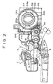
- Fig. 2 is a schematic sectional view showing the internal construction of the process cartridge.
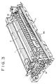
- Fig. 3 is a perspective view showing the internal construction of the process cartridge of which an upper case is removed.
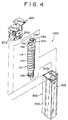
- Fig. 4 is an exploded perspective view showing the construction of the toner container of the present invention.
- Fig. 5 is an exploded perspective view showing the construction of a lid member of the toner container.
- Fig. 6 is an exploded perspective view showing the construction of a lid body of the lid member of the toner container.
- Fig. 7 is an exploded perspective view showing the construction of a toner discharge cover of the lid member of the toner container.
- Figs. 8(a) and 8(b) show the sealing of a toner discharge opening portion of the lid member of the toner container
- Fig. 8(a) is a sectional view showing a state before the sealing is completed
- Fig. 8(b) is a sectional view showing a state in which the sealing has been completed.
- Fig. 9 is an exploded perspective view showing the construction of a toner supply flange of the lid member of the toner container.
- Fig. 10(a) is a partly sectional front view of the toner supply flange of the lid member of the toner container
- Fig. 10(b) is a side view of Fig. 10(a).
- (A-A), (C-C), and (D-D) are sectional views taken along lines A-A, C-C, and D-D of Fig. 10(b), respectively, and (B-B) taken along line B-B of (A-A).
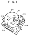
- Fig. 11 is a perspective view showing the lid body of the lid member of the toner container.
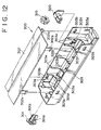
- Fig. 12 is an exploded perspective view showing the construction of an armoring member of the toner container.
- Fig. 13 is a perspective view showing a part of the reverse side of an upper case of the armoring member of the toner container.
- Fig. 14(a) is a top view showing the construction of a bearing of the armoring member of the toner container
- Fig. 14(b) is a front view of Fig. 14(a)
- Fig. 14(c) is a sectional view thereof
- Fig. 14(d) is a rear view thereof.
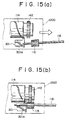
- Figs. 15(a) and 15(b) are descriptive drawings for describing the engagement between a bottle gear of a toner bottle of the toner container and a driving gear for driving the toner container
- Fig. 15(a) shows a state immediately before the gears are engaged with each other
- Fig. 15(b) shows a state in which the gears are in engagement with each other.
- Figs. 16(a) to 16(d) show procedure for attaching the toner container to the image forming apparatus.
- Fig. 17(a) is a perspective view showing the shape of a shoulder of the toner bottle of the present invention
- Fig. 17(b) is a perspective view showing the shape of a shoulder of a conventional toner bottle.
- FIG. 1 An embodiment of the present invention will be described in detail with reference to the attached drawings.
- a description will be provided of an image forming system of an image forming apparatus (a copying machine in this embodiment) to which a toner container according to the present invention is attached.
- the electricity is removed from a photoconductor 1 by illuminating it with electricity-removing light 7 while the photoconductor 1 is rotating in a direction of an arrow shown in Fig. 2.
- a surface potential of the photoconductor 1 is leveled to become a reference potential of 0 to - 150 v.
- the photoconductor 1 is charged by a charger 2, so that the surface potential thereof becomes - 900 v. or so.
- An exposure part of the charged photoconductor 1 is illuminated with image-forming light 3 whereas the remaining part (image-forming part) thereof which is not illuminated with the image-forming light 3 is imaged with toner staying on a development roller sleeve 4 of a development unit.
- a bias of about - 200 v. is applied to the development roller sleeve 4.
- the image-forming part of the photoconductor 1 that has not been illuminated with the image-forming light 3 maintains the surface potential of - 500 to - 850 v., the toner on the development roller sleeve 4 adheres to the image-forming part.
- Transfer paper is fed from a paper feeder (not shown) while the photoconductor 1 is further rotating.
- the transfer paper is fed with a given timing with which, in a transfer unit, a coincidence occurs between a front end of the transfer paper and a front end of stoner image formed on the photoconductor 1.
- the toner image is transferred to the transfer paper by means of a transfer device 5 of the transfer unit.
- the transfer paper to which the toner image has been transferred is sent to a fusing unit (not shown).
- the toner image of the transfer paper is fumed by the heat and pressure of a fuser (not shown) of the fusing unit, and thereafter the transfer paper as a duplicate is discharged from the apparatus (i.e., copying machine) outward.
- the toner remaining on the photoconductor 1 without being transferred to the transfer paper is scraped off by a cleaning blade 6 of a cleaning unit.
- the photoconductor 1 reaches an initial state of having no toner, and preparations are completed for the following image forming process.
- the charging device, the developing device, the cleaning device, which are disposed around the photoconductor, and the photoconductor are unitized and contained in a photoconductor-enclosing case 40 formed integrally.
- This case 40 is generally called as a process cartridge.
- the process cartridge has an external appearance as shown in Fig. 1.
- Figs. 2 and 3 in the process cartridge, the remaining toner which has been scraped off with the cleaning blade 6 from the photoconductor 1 is conveyed to a recycle toner conveying unit disposed in front of the case 40 by means of a toner conveying coil 8.
- the toner is then conveyed to a developer agitating portion of the development unit by means of a toner recycling belt 9 mounted in the recycle toner conveying unit and is used as recycle toner.
- the charger 2 and the transfer device 5 are of a roller type.
- the present invention is not limited to this.
- the present invention is applicable to a corona discharge type which uses wires.
- the development roller sleeve 4 has a fixed shaft in which magnets of five poles are mounted.
- the outer surface of the development roller sleeve 4 is covered with magnetic pipe material, such as aluminum. Because of the rotation of the pipe material, the developer (i.e., two-component developer consisting of a toner powder and carriers of small iron balls) contained in the developer container (case 40) is drawn to the development roller sleeve 4 by the magnetic force of the magnets and then is moved to the development part of the photoconductor 1.
- the developer i.e., two-component developer consisting of a toner powder and carriers of small iron balls
- the supply quantity of the developer from the development roller sleeve 4 to the photoconductor 1 is regulated by a doctor blade 10 that serves to make constant an inflow of the developer from the development roller sleeve 4 to the photoconductor 1.
- the developer container formed integrally with the case 40 includes a pair of agitating screws 11 for agitating and circulating the developer. Corresponding to the rotation of the agitating screws 11, the developer in the developer container is circulated as if to make loops, and is conveyed in an axial direction of the development roller sleeve 4 while being agitated.
- the carriers of the developer which have flowed to the development part of the photoconductor 1 are taken into the developer container and are again circulated therein by the rotation of the development roller sleeve 4, whereas the toner of the developer which has adhered to the carriers electrically charged by the agitation and has been conveyed to the development part of the photoconductor 1 is caused to adhere to an image forming area of the development part of the photoconductor 1 and is consumed. Accordingly, in this type of image forming apparatus, toner must be opportunely supplied according to the consumption, as widely known. For this reason, as shown in Figs. 1 and 2, a toner supply opening 12 through which new toner flows into the development container is formed in the upper part of the development container of the case 40 of the process cartridge.
- the toner container 1000 in this embodiment comprises a toner bottle 100 as a toner containing member which has a screw bottle construction, a lid member 200 attached to a mouth portion 114c of the bottle 100 and aligned with a toner discharge opening 114d of the bottle 100, and an armoring member 300 enclosing the toner bottle 100.
- the lid member 200 is provided with a toner supply mechanism for conveying the toner contained in the bottle 100 from the toner discharge opening 114d to the opening 12 of the case 40.
- This toner supply mechanism will be described later in detail. It is to be noted that a combination of the lid member 200 with the armoring member 300 can be regarded as a divided armoring member.
- the lid member 200 and the armoring member 300 are each shaped substantially like a quadrangle. Instead, they may be shaped like a polygon.
- the toner bottle 100 whose toner discharge opening 114d is in an opened state is inserted into the armoring member 300.
- the lid member 200 is attached to the toner bottle 100 and the armoring member 300 from above.
- the lid member 200 and the armoring member 300 are fixed to each other by the engagement between claws 201d formed on the end of the outer surface of the lid member 200 and claws 303d formed on the end of the inner surface of the armoring member 300.
- an adhesive agent or the like is not required for the assembly. This facilitates the assembly and disassembly of the parts, in other words, facilitates recycling.
- the toner bottle 100 has a spiral rib 114f on the inner surface of a bottle portion 114. Accordingly, when the toner bottle 100 is placed horizontally and is rotated about its center axis, toner contained in the toner bottle 100 is conveyed along the rib 114f and is discharged from the toner discharge opening 114d.
- a bottle gear 142 is mounted which is engaged with a toner container driving gear 115 which will be described later.
- the lid member 200 is attached to the mouth portion 114c of the toner bottle 100. As shown in Figs. 2 and 6, an opening 201e is formed in the inner surface of a lid body 201 of the lid member 200.
- a gate 219 is stuck over the opening 201e with, for example, adhesive double coated tape.
- the gate 219 is made of elastic material, such as PET film or rubber, and has a slit 219a used to supply an optimum quantity of toner.
- a gate seal 210 is stuck to the gate 219 (see Fig. 6). The gate seal 210 serves to prevent the toner from leaking out of the slit 219a of the gate 219 when the toner container 1000 is in an unused state.
- the gate seal 210 is removed from the gate 219.
- an end of the gate seal 210 which comes out of a seal-drawing slit 201a of the front of the lid body 201, is drawn by a user when the toner is used, and thereby the toner can be supplied.
- a toner discharge cover 204 is mounted on the outer opening surface of the lid body 201 so as to cover the gate 219 used as a toner supply opening on the aide of the lid body 201.
- a shutter-opening-and-closing spring 214 and a shutter 205 to which a shutter sheet 206 made of, for example, PET film is stuck with, for example, adhesive double coated tape are attached to the toner discharge cover.
- the shutter 205 is always pressed toward the lower part of the toner discharge cover 204 by extensible resilient forth. Thereby, a toner discharge opening 204a formed in the lower part of the toner discharge cover 204 is closed with the shutter sheet 206.
- the toner discharge opening 204a of the toner discharge cover 204 can serve as a toner discharge opening on the side of tie lid member 200.
- a projection 205a formed on the shutter 205 is pressed upward along a shutter-opening-and-closing slope (not shown) formed on the side of the apparatus.
- the shutter sheet 206 is moved from the position where the toner discharge opening 204a is closed with the shutter sheet 206, so that the toner can flow from the lid member 200 therothrough for replenishment.
- This shutter mechanism is provided for the purpose of preventing toner leakage when the toner container is handled.
- the sealing performance for preventing the toner leakage occurring when the toner container 1000 is, for example, transported is ensured by the gate seal 210.
- a seal member 207 and a seal member 208 are stuck to the toner discharge cover 204 with adhesive double coated tape or the like.
- the seal member 207 is used to secure the sealing ability between the toner discharge cover 204 and the lower surface of the lid body 201 whereas the seal member 208 is used to prevent toner from leaking from the seal-drawing slit 201a of the lid body 201.
- the seal members 207, 208 are each made of polyurethane foam.
- a seal member 212 is further stuck to the lid member 200 with adhesive double coated tape
- the seal member 212 is used to ensure the sealing ability between the toner discharge opening 204a formed on the side of the lid member 200 and the toner supply opening 12 formed on the side of the development unit when the toner container 1000 is set in the apparatus so as to bring about a coincidence between the toner discharge opening 204a and the toner supply opening 12.
- the seal member 212 comprises a thin plate 212a made of PET film and a sponge member 212b made of polyurethane foam which is directly stuck to the toner supply opening 12.
- the sponge member 212b is used to ensure elastic adhesion between the toner supply opening 12 and the toner discharge opening 204a and has an opening 212e bigger than the toner discharge opening 204a in the middle thereof, whereas the thin plate 212a has a plurality of notches 212c and flexible faces 212d at a part corresponding to the toner discharge opening 204a.
- a tapered surface 204c is formed on the lower side in the drawing, i.e., on the side of a surface facing the toner supply opening 12.
- the side of the opening 212e of the sponge member 212b is determined to such an extent that the tapered surface 204c is not covered with the sponge member 212b.
- the sponge member 212b is stuck on a part around the opening 204a, and the thin plate 212a is stuck on the sponge member 212b.
- the thin plate 212a is then bent with operator's fingers, so that its flexible part 212d is stuck on the tapered surface 204c. Thereby, there is formed a path of a chamfered construction having a sealing ability.
- toner T is liable to adhere to the sponge member 212b. Accordingly, when the toner container 1000 is replaced, the toner T which has adhered to the sponge member 212b falls off because of vibrations, and the apparatus is contaminated with the toner T.
- the sponge member 212b is covered with the thin plate 212a, and the path from the toner discharge opening 204a to the toner supply opening 12 has a tapered shape by the use of the thin plate 212a, as shown in Figs. 8(a) and 8(b).
- the adhesion of the toner T to the sponge member 212b can be restrained to avoid toner contamination, and additionally a good sealing function can be obtained.
- the inside of the lid body 201 of the lid member 200 is shaped cylindrically as shown in Fig. 2.
- a toner supply flange 216 is rotatably attached to the inside.
- the flange 216 is shaped like a cylindrical cap and has an opening 216d in the middle of its end face.
- the toner discharge opening 114d of the toner bottle 100 is fitted in the opening 216d of the flange 216 by inserting the mouth portion 114c of the toner bottle 100 into the inside of the flange 216.
- Two brackets 216a substantially vertically jutting out of the end face of the flange 216 are mounted around the opening 216d.
- the brackets 216a are formed integrally with the flange 216.
- a toner pushing member 217 made of flexible material, such as PET film, is stuck to the bracket 216a with adhesive double coated tape.
- the toner pushing member 217 is stuck thereto such that a free end of the toner pushing member 217 adheres elastically to the internal surface of the inside of the lid body 201 when the flange 216 is attached to the lid body 201, as shown in Fig. 2.
- a band-like seal member 209 made of polyurethane foam is stuck to the external surface of the flange 216.
- an annular seal member made of polyurethane foam is stuck to the part around the opening 216d with adhesive double coated tape.
- a sectionally T-shaped projection 201g is mounted on the bottom of the cylindrical lid body 201.
- the T-shaped projection 201g is arranged to be situated in the vicinity of the upper position in the toner discharge opening 114d when the toner bottle is set.
- a sheet-like scraper 1001 for scraping off toner around the toner discharge opening 114d is stuck to the middle of the projection 201g with adhesive double coated tape. Seeing from the rotational direction N of the toner bottle 100, the stuck position of the scraper 1001 is on the front side of the middle of the projection 201g.
- the scraper 1001 is made of PET film and, as shown in Fig. 6, comprises a stuck part 1001a and a scraping part 1001c with an edge 1001b.
- the scraper 1001 enters the toner discharge opening 114d of the toner bottle 100, and the edge 1001b of the scraper 1001 comes in contact with the circumferential surface around the opening 114d.
- the edge 1001b scrapes the circumferential surface.
- the toner is prevented from stagnating around the toner discharge opening 114d, and a stable toner replenishment can be obtained.
- the scraper 1001 is designed so that the scraper 1001 alone is bent when the scraper 1001 comes in contact with the toner bottle 100. For this reason, the scraper 1001 has a very weak sliding resistance and can hardly exert influence on the driving torque of the toner bottle 100. Additionally, since the stuck position of the scraper 1001 is on the front side of the middle of the projection 201g when seen from the rotational direction N of the toner bottle 100, the sliding resistance of the scraper 1001 to the toner discharge opening 114d acts to aid the scraper 1001 in sticking. As a result, the scraper 1001 is in a state difficult to tear off.
- toner container 1000 it is desirable to make the toner discharge opening 114d small in diameter, in order to improve the opening and closing function of the toner containing member.
- the shortening of the diameter of the toner discharge opening 114d exerts an unfavorable influence on the flow of toner at the toner discharge opening 114d
- the toner discharge opening 114d is closed with some kind of toner, depending on the physical properties of the toner. For this reason, only toner excellent in fluidity can be used, in other words, there are certain restrictions as to the kind of toner to be used.
- an advantage of the present invention is that there is no restrictions on the type of an object to which the toner container is attached (i.e., the type of an image forming apparatus).
- the armoring member 300 comprises a bearing 301, an upper case 302, and a lower case 303.
- the upper and lower cases 302, 303 are fixed to each other by the engagement of claws 302a formed on the upper case 302 with holes 303b formed in the lower case 303, respectively. Therefore, there is no need to use an adhesive agent or the like when they are assembled into the armoring member 300. Thus, the assembly or disassembly of the parts is facilitated.
- the upper case 302 is made of polystyrene (PS), and the claws 302a are each set to be about 1.5 mm in thickness.
- a reinforcing rib 302c is formed integrally with the root of the claw 302a, as shown in Fig. 13 which is a partial view showing a state where the upper case 302 is reversed.
- the angle ⁇ of the reinforcing rib 302c is set at 45 degrees. The reinforcement of the reinforcing rib 302c ensures the locking function performed by the engagement between the claw 302a and the hole 303b for a long time.
- a plurality of ribs extending in longitudinal and lateral directions of the upper case 302 are formed on the rear face of the upper case 302. Additionally, an engagement rib 302d semi-spherical in section is formed on the rear face all over the periphery of the upper case 302. Corresponding to the engagement rib 302d, reinforcing ribs 303f each of which has notched concaves 303e at the upper part thereof are formed in the lower case 303. When the upper case 302 is fitted to the lower case 303, the engagement rib 302d is engaged with the notched concaves 303e.
- the strength of the upper case 302 itself is further heightened. Additionally, regardless of whether the distance between both the walls of the lower case 303 which extend in the longitudinal direction is shorter or longer than a predetermined length, accurate dimension and positioning are obtained by fitting the upper case 302 to the lower case 303 so that the engagement rib 302d is engaged with the notched concaves 303e. The aforementioned walls of the lower case 303 to which the upper case 302 has been fitted cannot be crushed even if the walls are pressed inward. In other words, the engagement rib 302d serves to supplement a weak point occurring when the armoring member 300 is constructed out of separate parts, and accordingly the strength of all the cases of the armoring member 300 is maintained. Additionally, as described above, since accurate length and positioning are obtained by fitting the upper case 302 to the lower case 303 regardless of errors in dimension, strict requirements for accuracy in manufacturing can be moderated, and therefore productivity can be improved.
- the bearing 301 is fixed to the lower case 303 such that a snap claw 301b, as shown in Figs. 14(a), extending in the axial direction of the bearing 301 is fitted, with a snap, to a bearing-supporting portion 303a of the lower case 303 of the armoring member 300 shown in Fig. 12.
- a rib 301c for regulating the bend of the snap claw 301b is formed at the root of the snap claw 301b.
- a tapered portion 301a is mounted on the lower side of the axis of the bearing 301.
- the tapered portion 301a serves to slide the tip of the driving shaft 116 of the toner-container-driving gear 115 disposed on the side of the apparatus on an inclined face of the tapered portion 301a from below to above when the toner container 1000 is inserted into the apparatus.
- the toner-container-driving gear 115 comes in engagement with the bottle gear 142 mounted on the bottle portion 114 of the toner bottle 100 from a direction perpendicular to its rotational axis, and thus the toner container 1000 is very smoothly attached to the apparatus.
- a bottle tapping roller 319 with ratchet-like teeth on its periphery is fixed to the lower case 303 of the armoring member 300 via a roller supporting bracket 320 made of a flat spring.
- the bottle tapping roller 319 With the toner bottle 100 housed in the armoring member 300, the bottle tapping roller 319 is disposed to be in elastic contact with the side face of the bottle portion 114. Accordingly, when the toner bottle 100 rotates under a toner supplying operation which will be later described, the roller 319 is rolled because of differences in level of the circumferential surface of the bottle portion 114 and gives vibrations to the toner bottle 100. Thus, the toner is prevented from adhering to the inner surface of the toner bottle 100.
- FIGs. 2 and 3 when a toner density sensor 34 comprising a permeability sensor for detecting the permeability of a developer detects that the toner density of a developer circulating in the developer container is less than a reference toner density, a driving portion (not shown) mounted on the side of the apparatus is actuated to turn the toner-container-driving gear 115 shown in Figs. 15(a) and 15(b).
- the toner-container-driving gear 115 comes in engagement with the bottle gear 142 of the toner bottle 100 by setting the toner container 1000 in the apparatus. Accordingly, the toner bottle 100 is rotated in a predetermined direction correspondingly to the rotation of the toner-contained-driving gear 115 that is in engagement with the bottle gear 142.
- projections 114a (see Fig. 4) formed on the head of the toner bottle 100 are engaged with ribs 216b (see Fig. 10(b)) formed on the internal wall of the toner supply flange 216, respectively, and thereby the toner bottle 100 is rotated simultaneously with the rotation of the flange 216.
- the toner bottle 100 runs idle for disengagement between the projection 114a and the rib 216b which is caused by abrasion, or the like, of the projection 114a.
- projections 216c to be engaged with an inclined portion 114b of the shoulder of the toner bottle 100 are formed on the internal surface of the flange 216.
- the toner By the rotation of the toner bottle 100, the toner is conveyed toward the opening formed in the end of the toner container 1000 by the aid of the toner conveying function of the spiral rib 114f of the bottle portion 114, and is discharged from the toner discharge opening 114d.
- the discharged toner is first caused to flow into a toner hopper (in a rotation path of the toner pushing member 217) defined between the lid body 201 and the flange 216, as shown in Fig. 2.
- the toner in the toner hopper is then raked and pushed up to flow on the inner circumferential surface of the lid body 201 by means of the toner pushing member 217 that is rotated substantially simultaneously with the rotation of the flange 216.
- the toner pushing member 217 passes the gate 219, the toner is pushed out of the inside of the lid body 201 through the slit 219a of the gate 219.
- the toner that has been pushed out therefrom falls inside the toner discharge cover 204 attached to the side wall of the lid body 201 and then is supplied to the development unit through the toner discharge opening 204a formed in the lower part of the toner discharge cover 204 and the toner supply opening 12 of the development unit which faces the toner discharge opening 204a.
- the toner supply to the development unit is controlled by the toner density sensor 34 that detects the toner density of a developer circulating in the developer container.
- the toner density sensor 34 detects a state where the toner density of the developer has reached a reference toner density after the toner is supplied from the toner container 1000 to the developing unit, the driving shaft 116 of the toner-container-driving gear 115 is stopped from rotating, and thereby the toner supply is stopped.
- the toner is timely supplied to the development unit in this way, and a toner end display (not shown) mounted in the apparatus is lighted when all the toner in the toner bottle 100 is used up. A user sees the bright display and ascertains that the toner bottle 100 contains no toner. The user then replaces the empty toner container with a new toner container filled with toner. Taking the steps shown in Figs. 16(a) to 16(d), the old toner container is replaced with the new one.
- the user first opens a front cover of the apparatus and presses a stopper 117 down, and then takes the old toner container 1000 out of the apparatus. After that, as shown in Fig. 16(b), the user shakes a new toner container 1000 five or six times so that toner in the toner container 1000 can flow easily and smoothly.
- the new toner container 1000 is attached to the apparatus. At this time, the user ascertains whether the new toner container 1000 has been properly set therein or not by hearing a locking snap of the stopper 117 or by discerning a locked position.
- a gate seal 210 of the new toner container 1000 is drawn out. Thereby, the toner is ready to be supplied. At the end, the user closes the front cover.
- the positioning of the toner container 1000 with respect to the process cartridge is carried out by the engagement of a positioning hole 201b (see Fig. 5) formed in a handle of the lid member 200 of the toner container 1000 with a positioning pin 118 (see Fig. 1) of the process cartridge, and the positioning of the toner container 1000 with respect to the apparatus is carried out by the engagement of a positioning hole 201c (see Fig. 5) formed in the lid body 201 of the toner container 1000 with a positioning pin (not shown) of the apparatus.
- the lid member 200 is positioned and fastened to the apparatus, and thereby the armoring member 300 is simultaneously positioned and fastened to the apparatus. In the event that a combination of the lid member 200 with the armoring member 300 is regarded as an armoring member, the same step is taken.
- the shoulder of the mouth portion 114c of the toner bottle 100 is shaped such that the width of a spiral groove 114e used as a toner conveying path is greater than that of a spiral groove 114e of a conventional toner bottle 100' shown in Fig. 17(b). Therefore, the toner bottle 100 according to this embodiment discharges more toner per rotation than the conventional toner bottle 100'. This makes it possible to put a sufficient quantity of toner into the toner hopper of the lid member 200 of the toner container 1000, and thus always stably supply the toner from the toner container 1000 to the development unit.
Landscapes
- Physics & Mathematics (AREA)
- General Physics & Mathematics (AREA)
- Dry Development In Electrophotography (AREA)
Applications Claiming Priority (9)
| Application Number | Priority Date | Filing Date | Title |
|---|---|---|---|
| JP14729096 | 1996-06-10 | ||
| JP14729096 | 1996-06-10 | ||
| JP147290/96 | 1996-06-10 | ||
| JP15573896 | 1996-06-17 | ||
| JP155738/96 | 1996-06-17 | ||
| JP15573896 | 1996-06-17 | ||
| JP92229/97 | 1997-04-10 | ||
| JP9222997 | 1997-04-10 | ||
| JP09222997A JP3527384B2 (ja) | 1996-06-10 | 1997-04-10 | トナー収容容器 |
Publications (2)
| Publication Number | Publication Date |
|---|---|
| EP0813121A1 true EP0813121A1 (fr) | 1997-12-17 |
| EP0813121B1 EP0813121B1 (fr) | 2002-11-06 |
Family
ID=27306975
Family Applications (1)
| Application Number | Title | Priority Date | Filing Date |
|---|---|---|---|
| EP97109390A Expired - Lifetime EP0813121B1 (fr) | 1996-06-10 | 1997-06-10 | Récipient de toner et appareil de formation d'images équipé d'un tel récipient |
Country Status (6)
| Country | Link |
|---|---|
| US (1) | US5909610A (fr) |
| EP (1) | EP0813121B1 (fr) |
| JP (1) | JP3527384B2 (fr) |
| CN (1) | CN1098474C (fr) |
| DE (1) | DE69716816T2 (fr) |
| ES (1) | ES2184923T3 (fr) |
Cited By (4)
| Publication number | Priority date | Publication date | Assignee | Title |
|---|---|---|---|---|
| EP1220050A3 (fr) * | 2000-12-25 | 2003-01-02 | Ricoh Company, Ltd. | Dispositif de réapprovisionnement de toner et dispositif de formation d'images avec celui-ci |
| US9135430B2 (en) | 2004-03-31 | 2015-09-15 | Rockwell Automation Technologies, Inc. | Digital rights management system and method |
| EP2511772A3 (fr) * | 2011-02-17 | 2016-10-19 | Ricoh Company, Ltd. | Récipient pour poudre, dispositif de fourniture de poudre et appareil de formation d'images |
| EP3709092A1 (fr) * | 2019-03-13 | 2020-09-16 | Ricoh Company, Ltd. | Récipient de toner, dispositif d'alimentation en toner et appareil de formation d'images |
Families Citing this family (33)
| Publication number | Priority date | Publication date | Assignee | Title |
|---|---|---|---|---|
| TW240299B (fr) | 1992-12-30 | 1995-02-11 | Ricoh Kk | |
| USD442623S1 (en) | 1996-08-27 | 2001-05-22 | Ricoh Company, Ltd. | Toner bottle |
| US5970293A (en) * | 1999-01-29 | 1999-10-19 | General Plastic Industrial Co., Ltd. | Developer container for use with a developer replenishing device |
| US6188859B1 (en) * | 1999-03-31 | 2001-02-13 | General Plastic Industrial Co. | Structure of developer replenishing container |
| JP2001159848A (ja) | 1999-12-01 | 2001-06-12 | Ricoh Co Ltd | 画像形成装置 |
| USD450081S1 (en) | 1999-12-27 | 2001-11-06 | Konica Corporation | Toner cartridge |
| USD442986S1 (en) | 1999-12-27 | 2001-05-29 | Konica Corporation | Toner cartridge |
| US6334037B1 (en) | 2000-02-18 | 2001-12-25 | Toshiba Tec Kabushiki Kaisha | Image forming apparatus |
| US6289182B1 (en) | 2000-02-18 | 2001-09-11 | Toshiba Tec Kabushiki Kaisha | Method and apparatus for discriminating toner bottle types, stirring toner, and detecting the amount of remaining toner |
| AU144171S (en) | 2000-05-12 | 2001-06-07 | Toshiba Tec Kk | Toner storage container for a copying machine |
| USD446807S1 (en) | 2000-06-22 | 2001-08-21 | Fuji Xerox Co., Ltd. | Container for image forming apparatus |
| EP1227372A1 (fr) | 2001-01-30 | 2002-07-31 | Ricoh Company, Ltd. | Dispositif pour empêcher la dispersion de toner et appareil de formation d'images l'utilisant |
| EP1233310B1 (fr) | 2001-02-19 | 2009-12-23 | Canon Kabushiki Kaisha | Récipient d'alimentation en toner et système d'alimentation en toner |
| US6990301B2 (en) * | 2001-02-19 | 2006-01-24 | Canon Kabushiki Kaisha | Sealing member, toner accommodating container and image forming apparatus |
| JP2003177604A (ja) * | 2001-12-11 | 2003-06-27 | Ricoh Co Ltd | トナー飛散防止装置および画像形成装置 |
| JP2003289422A (ja) * | 2002-01-24 | 2003-10-10 | Ricoh Co Ltd | 画像読取装置 |
| EP1369752B1 (fr) * | 2002-06-03 | 2008-03-26 | Ricoh Company, Ltd. | Appareil de formation d'images muni d'une lame de nettoyage |
| JP2004139031A (ja) | 2002-09-24 | 2004-05-13 | Ricoh Co Ltd | 画像形成装置、補給用トナー収容器およびプロセスカートリッジ |
| JP2004226695A (ja) * | 2003-01-23 | 2004-08-12 | Ricoh Co Ltd | 画像形成装置用現像装置の軸受シール構造、現像装置、及び画像形成装置 |
| JP4383898B2 (ja) | 2003-02-28 | 2009-12-16 | 株式会社リコー | 現像剤収容器、現像剤供給装置及び画像形成装置 |
| JP2005221825A (ja) * | 2004-02-06 | 2005-08-18 | Ricoh Co Ltd | トナーボトル及びその製造方法、トナー容器、トナーカートリッジ並びに、画像形成装置 |
| JP4656561B2 (ja) * | 2004-03-05 | 2011-03-23 | 株式会社リコー | トナー容器、トナー補給装置、現像装置、プロセスカートリッジ、及び、画像形成装置 |
| US7720416B2 (en) | 2004-08-16 | 2010-05-18 | Ricoh Company, Ltd. | Method and toner bottle for image forming apparatus capable of effectively supplying toner to image forming apparatus |
| CN100511008C (zh) * | 2004-10-29 | 2009-07-08 | 兄弟工业株式会社 | 成像装置中的处理盒 |
| JP4815932B2 (ja) * | 2004-10-29 | 2011-11-16 | ブラザー工業株式会社 | プロセスカートリッジおよび画像形成装置 |
| JP4905689B2 (ja) * | 2007-02-21 | 2012-03-28 | 村田機械株式会社 | トナーカートリッジ |
| JP5017475B1 (ja) | 2011-04-15 | 2012-09-05 | 京セラドキュメントソリューションズ株式会社 | 画像形成装置およびトナーコンテナ |
| WO2013015455A1 (fr) | 2011-07-27 | 2013-01-31 | Ricoh Company, Ltd. | Récipient de révélateur, dispositif de développement, unité de traitement et appareil de formation d'image |
| JP5640935B2 (ja) * | 2011-09-14 | 2014-12-17 | コニカミノルタ株式会社 | トナー補給機構 |
| US8977160B2 (en) | 2011-12-30 | 2015-03-10 | Lexmark International, Inc. | Overmolded shutter for use in toner containing supply items of an imaging apparatus |
| US9042791B2 (en) | 2012-03-27 | 2015-05-26 | Fuji Xerox Co., Ltd. | Powder accommodation container, image forming apparatus and manufacturing method of the image forming apparatus |
| JP2020134711A (ja) * | 2019-02-20 | 2020-08-31 | 富士ゼロックス株式会社 | 清掃装置、画像形成装置および転写装置 |
| JP2025079881A (ja) * | 2023-11-13 | 2025-05-23 | キヤノン株式会社 | 定着装置及び画像形成装置 |
Citations (4)
| Publication number | Priority date | Publication date | Assignee | Title |
|---|---|---|---|---|
| JPH06194950A (ja) * | 1992-12-23 | 1994-07-15 | Ricoh Co Ltd | トナー補給容器 |
| EP0616268A1 (fr) * | 1993-03-14 | 1994-09-21 | Ricoh Company, Ltd | Récipient de toner et dispositif de réapprovisionnement de toner |
| US5424816A (en) * | 1994-06-27 | 1995-06-13 | Xerox Corporation | Toner cartridge |
| DE19541680A1 (de) * | 1994-11-08 | 1996-05-09 | Ricoh Kk | Toner-Nachfüllvorrichtung für eine Entwicklungsvorrichtung |
Family Cites Families (8)
| Publication number | Priority date | Publication date | Assignee | Title |
|---|---|---|---|---|
| JPH0725806Y2 (ja) * | 1989-10-19 | 1995-06-07 | 沖電気工業株式会社 | トナーカートリッジ |
| DE69122727T2 (de) * | 1990-07-10 | 1997-05-22 | Oki Electric Ind Co Ltd | Tonerbehälter |
| US5416568A (en) * | 1991-07-09 | 1995-05-16 | Ricoh Company, Ltd. | Developing unit for an image forming apparatus |
| JP2982450B2 (ja) * | 1991-11-26 | 1999-11-22 | 日本電気株式会社 | フィルムキャリア半導体装置及びその製造方法 |
| TW240299B (fr) * | 1992-12-30 | 1995-02-11 | Ricoh Kk | |
| JP3080828B2 (ja) * | 1994-01-14 | 2000-08-28 | 京セラミタ株式会社 | 用紙送り装置 |
| US5648840A (en) * | 1994-11-14 | 1997-07-15 | Konica Corporation | Image forming apparatus including toner conveyance apparatus |
| US5722019A (en) * | 1996-01-29 | 1998-02-24 | Oki Data Corporation | Toner cartridge and drum cartridge for receiving the toner cartridge therein |
-
1997
- 1997-04-10 JP JP09222997A patent/JP3527384B2/ja not_active Expired - Fee Related
- 1997-06-09 CN CN97112134A patent/CN1098474C/zh not_active Expired - Lifetime
- 1997-06-10 ES ES97109390T patent/ES2184923T3/es not_active Expired - Lifetime
- 1997-06-10 DE DE69716816T patent/DE69716816T2/de not_active Expired - Lifetime
- 1997-06-10 EP EP97109390A patent/EP0813121B1/fr not_active Expired - Lifetime
- 1997-06-10 US US08/872,049 patent/US5909610A/en not_active Expired - Lifetime
Patent Citations (4)
| Publication number | Priority date | Publication date | Assignee | Title |
|---|---|---|---|---|
| JPH06194950A (ja) * | 1992-12-23 | 1994-07-15 | Ricoh Co Ltd | トナー補給容器 |
| EP0616268A1 (fr) * | 1993-03-14 | 1994-09-21 | Ricoh Company, Ltd | Récipient de toner et dispositif de réapprovisionnement de toner |
| US5424816A (en) * | 1994-06-27 | 1995-06-13 | Xerox Corporation | Toner cartridge |
| DE19541680A1 (de) * | 1994-11-08 | 1996-05-09 | Ricoh Kk | Toner-Nachfüllvorrichtung für eine Entwicklungsvorrichtung |
Non-Patent Citations (1)
| Title |
|---|
| PATENT ABSTRACTS OF JAPAN vol. 018, no. 546 (P - 1814) 18 October 1994 (1994-10-18) * |
Cited By (6)
| Publication number | Priority date | Publication date | Assignee | Title |
|---|---|---|---|---|
| EP1220050A3 (fr) * | 2000-12-25 | 2003-01-02 | Ricoh Company, Ltd. | Dispositif de réapprovisionnement de toner et dispositif de formation d'images avec celui-ci |
| US9135430B2 (en) | 2004-03-31 | 2015-09-15 | Rockwell Automation Technologies, Inc. | Digital rights management system and method |
| US10027489B2 (en) | 2004-03-31 | 2018-07-17 | Rockwell Automation Technologies, Inc. | Digital rights management system and method |
| EP2511772A3 (fr) * | 2011-02-17 | 2016-10-19 | Ricoh Company, Ltd. | Récipient pour poudre, dispositif de fourniture de poudre et appareil de formation d'images |
| EP3709092A1 (fr) * | 2019-03-13 | 2020-09-16 | Ricoh Company, Ltd. | Récipient de toner, dispositif d'alimentation en toner et appareil de formation d'images |
| US11048189B2 (en) | 2019-03-13 | 2021-06-29 | Ricoh Company, Ltd. | Toner container, toner supply device, and image forming apparatus including a sheet member with two portions to move toner |
Also Published As
| Publication number | Publication date |
|---|---|
| HK1006497A1 (en) | 1999-03-05 |
| EP0813121B1 (fr) | 2002-11-06 |
| JP3527384B2 (ja) | 2004-05-17 |
| JPH1069160A (ja) | 1998-03-10 |
| ES2184923T3 (es) | 2003-04-16 |
| CN1168495A (zh) | 1997-12-24 |
| US5909610A (en) | 1999-06-01 |
| CN1098474C (zh) | 2003-01-08 |
| DE69716816T2 (de) | 2003-09-11 |
| DE69716816D1 (de) | 2002-12-12 |
Similar Documents
| Publication | Publication Date | Title |
|---|---|---|
| EP0813121B1 (fr) | Récipient de toner et appareil de formation d'images équipé d'un tel récipient | |
| US5557382A (en) | Toner replenishing device for a developing device | |
| JP3541691B2 (ja) | 画像形成装置及び現像剤収納容器 | |
| KR100488374B1 (ko) | 토너 보급 용기 | |
| JP3305159B2 (ja) | 現像装置 | |
| US9395650B2 (en) | Developer container and image forming apparatus including the same | |
| JPH096113A (ja) | 現像装置 | |
| JPH09244369A (ja) | トナー容器 | |
| US20160033903A1 (en) | Developer container and image forming apparatus including the same | |
| JPH07199623A (ja) | トナーカートリッジ及び現像剤補給方法及び現像装置 | |
| US20160033897A1 (en) | Developer container and image forming apparatus including the same | |
| JP3297534B2 (ja) | トナー補給容器、プロセスカートリッジ及び画像形成装置 | |
| US9383679B2 (en) | Developer container and image forming apparatus including the same | |
| JP3578889B2 (ja) | トナーカートリッジ | |
| JP3648355B2 (ja) | 画像形成装置 | |
| JP3545916B2 (ja) | トナー補給機構 | |
| JPH1130906A (ja) | 画像形成装置 | |
| JP3889477B2 (ja) | トナー補給装置 | |
| JPH10142912A (ja) | 画像形成装置 | |
| JP2002174947A (ja) | 現像剤収納容器及び画像形成装置 | |
| JPH10293451A (ja) | トナーカートリッジ | |
| JP2004170553A (ja) | トナー供給装置およびトナー供給装置を備えた画像形成装置 | |
| JPH07199622A (ja) | トナーカートリッジ及び現像装置 | |
| EP0740219A2 (fr) | Unité de développement et récipient de toner | |
| JPH09269643A (ja) | トナー/現像剤供給・回収機構及びその構成部材 |
Legal Events
| Date | Code | Title | Description |
|---|---|---|---|
| PUAI | Public reference made under article 153(3) epc to a published international application that has entered the european phase |
Free format text: ORIGINAL CODE: 0009012 |
|
| 17P | Request for examination filed |
Effective date: 19970710 |
|
| AK | Designated contracting states |
Kind code of ref document: A1 Designated state(s): DE ES FR GB IT |
|
| AKX | Designation fees paid |
Free format text: DE ES FR GB IT |
|
| RBV | Designated contracting states (corrected) |
Designated state(s): DE ES FR GB IT |
|
| 17Q | First examination report despatched |
Effective date: 20010718 |
|
| GRAG | Despatch of communication of intention to grant |
Free format text: ORIGINAL CODE: EPIDOS AGRA |
|
| GRAG | Despatch of communication of intention to grant |
Free format text: ORIGINAL CODE: EPIDOS AGRA |
|
| GRAH | Despatch of communication of intention to grant a patent |
Free format text: ORIGINAL CODE: EPIDOS IGRA |
|
| GRAH | Despatch of communication of intention to grant a patent |
Free format text: ORIGINAL CODE: EPIDOS IGRA |
|
| GRAA | (expected) grant |
Free format text: ORIGINAL CODE: 0009210 |
|
| AK | Designated contracting states |
Kind code of ref document: B1 Designated state(s): DE ES FR GB IT |
|
| REG | Reference to a national code |
Ref country code: GB Ref legal event code: FG4D |
|
| REF | Corresponds to: |
Ref document number: 69716816 Country of ref document: DE Date of ref document: 20021212 |
|
| REG | Reference to a national code |
Ref country code: ES Ref legal event code: FG2A Ref document number: 2184923 Country of ref document: ES Kind code of ref document: T3 |
|
| RIN2 | Information on inventor provided after grant (corrected) |
Inventor name: KUSUNOSE, NOBORU Inventor name: YOSHIKI, SHIGERU |
|
| ET | Fr: translation filed | ||
| PLBE | No opposition filed within time limit |
Free format text: ORIGINAL CODE: 0009261 |
|
| STAA | Information on the status of an ep patent application or granted ep patent |
Free format text: STATUS: NO OPPOSITION FILED WITHIN TIME LIMIT |
|
| 26N | No opposition filed |
Effective date: 20030807 |
|
| REG | Reference to a national code |
Ref country code: FR Ref legal event code: PLFP Year of fee payment: 19 |
|
| PGFP | Annual fee paid to national office [announced via postgrant information from national office to epo] |
Ref country code: DE Payment date: 20150619 Year of fee payment: 19 Ref country code: GB Payment date: 20150618 Year of fee payment: 19 Ref country code: ES Payment date: 20150619 Year of fee payment: 19 |
|
| PGFP | Annual fee paid to national office [announced via postgrant information from national office to epo] |
Ref country code: IT Payment date: 20150622 Year of fee payment: 19 Ref country code: FR Payment date: 20150619 Year of fee payment: 19 |
|
| REG | Reference to a national code |
Ref country code: DE Ref legal event code: R119 Ref document number: 69716816 Country of ref document: DE |
|
| GBPC | Gb: european patent ceased through non-payment of renewal fee |
Effective date: 20160610 |
|
| REG | Reference to a national code |
Ref country code: FR Ref legal event code: ST Effective date: 20170228 |
|
| PG25 | Lapsed in a contracting state [announced via postgrant information from national office to epo] |
Ref country code: FR Free format text: LAPSE BECAUSE OF NON-PAYMENT OF DUE FEES Effective date: 20160630 Ref country code: DE Free format text: LAPSE BECAUSE OF NON-PAYMENT OF DUE FEES Effective date: 20170103 |
|
| PG25 | Lapsed in a contracting state [announced via postgrant information from national office to epo] |
Ref country code: GB Free format text: LAPSE BECAUSE OF NON-PAYMENT OF DUE FEES Effective date: 20160610 |
|
| PG25 | Lapsed in a contracting state [announced via postgrant information from national office to epo] |
Ref country code: IT Free format text: LAPSE BECAUSE OF NON-PAYMENT OF DUE FEES Effective date: 20160610 |
|
| REG | Reference to a national code |
Ref country code: ES Ref legal event code: FD2A Effective date: 20180507 |
|
| PG25 | Lapsed in a contracting state [announced via postgrant information from national office to epo] |
Ref country code: ES Free format text: LAPSE BECAUSE OF NON-PAYMENT OF DUE FEES Effective date: 20160611 |