EP0814205A2 - Flèche pour un véhicule - Google Patents
Flèche pour un véhicule Download PDFInfo
- Publication number
- EP0814205A2 EP0814205A2 EP97890106A EP97890106A EP0814205A2 EP 0814205 A2 EP0814205 A2 EP 0814205A2 EP 97890106 A EP97890106 A EP 97890106A EP 97890106 A EP97890106 A EP 97890106A EP 0814205 A2 EP0814205 A2 EP 0814205A2
- Authority
- EP
- European Patent Office
- Prior art keywords
- rocker
- arm
- attached
- boom
- rocker arms
- Prior art date
- Legal status (The legal status is an assumption and is not a legal conclusion. Google has not performed a legal analysis and makes no representation as to the accuracy of the status listed.)
- Ceased
Links
Images

Classifications
-
- E—FIXED CONSTRUCTIONS
- E02—HYDRAULIC ENGINEERING; FOUNDATIONS; SOIL SHIFTING
- E02F—DREDGING; SOIL-SHIFTING
- E02F9/00—Component parts of dredgers or soil-shifting machines, not restricted to one of the kinds covered by groups E02F3/00 - E02F7/00
- E02F9/08—Superstructures; Supports for superstructures
- E02F9/085—Ground-engaging fitting for supporting the machines while working, e.g. outriggers, legs
-
- E—FIXED CONSTRUCTIONS
- E02—HYDRAULIC ENGINEERING; FOUNDATIONS; SOIL SHIFTING
- E02F—DREDGING; SOIL-SHIFTING
- E02F9/00—Component parts of dredgers or soil-shifting machines, not restricted to one of the kinds covered by groups E02F3/00 - E02F7/00
- E02F9/02—Travelling-gear, e.g. associated with slewing gears
- E02F9/028—Travelling-gear, e.g. associated with slewing gears with arrangements for levelling the machine
-
- E—FIXED CONSTRUCTIONS
- E02—HYDRAULIC ENGINEERING; FOUNDATIONS; SOIL SHIFTING
- E02F—DREDGING; SOIL-SHIFTING
- E02F9/00—Component parts of dredgers or soil-shifting machines, not restricted to one of the kinds covered by groups E02F3/00 - E02F7/00
- E02F9/02—Travelling-gear, e.g. associated with slewing gears
- E02F9/04—Walking gears moving the dredger forward step-by-step
Definitions
- the invention relates to a boom for a vehicle with a main arm pivotally attached to the vehicle frame and a rocker arm pivotally attached to the main arm, to which a work tool is attached.
- the invention is therefore based on the object of providing a boom which can be used very well as a locomotion aid without the risk that the harvester head is damaged or that its possible uses are restricted.
- a generic vehicle is known from US 4,444,542 A.
- two arms are mounted parallel to one another on the frame of a turntable, each arm consisting of a main arm and a rocker arm pivotably mounted on it.
- There is a working tool on the luffing arm of each boom e.g. an excavator shovel and a hydraulic hammer attached.
- the technical effort can be considerably reduced, since only a single main arm has to be provided, so that only a single hydraulic cylinder is required to actuate the main arm, which has an advantageous effect on the costs of the boom.
- the weight can also be considerably reduced in comparison to the vehicle of US 4,444,542 A, which is very important in particular in the case of woodworking machines which have to move in the forest and on steep and rough terrain.
- the boom according to the invention also has the advantage that existing booms on vehicles can be easily replaced by a boom according to the invention without special changes in the mounting of the main arm on the vehicle frame being necessary, since only a single main arm is still provided, whereas the Vehicle according to US 4,444,542 A a second storage for the separate rocker arm is required. Finally, a visual obstruction by the second boom during work is avoided.
- the two rocker arms attached to the main arm can either be pivoted together or independently of one another on the main arm.
- a Harverster head is attached to a rocker arm.
- On the other rocker arm there is a device that can be used as a locomotion aid. This can be, for example, a conventional excavator shovel or a pile-like tool with which the working machine can be supported at a suitable location in the field eg to overcome a steep incline or an obstacle.
- the locomotion aid is located on a second rocker arm, the tool on the first rocker arm is not exposed to the risk of damage and its use is in no way restricted.
- Front loaders for work vehicles are described in US 4,797,051 A and DE 27 14 613 A1.
- parking supports are attached to the front loaders, which are folded up or pushed in during operation and are therefore inoperative.
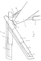
- Fig. 1 an embodiment of a boom according to the invention is shown schematically, wherein the mounting of the main arm 1 on the vehicle and the vehicle itself are not shown, since it can be conventional bearings or vehicles that are not for the present invention are of particular importance.
- the boom 1 is preferably mounted on a so-called walking excavator known per se, the spider legs of which can be extended and which enable a very strong level compensation.
- the boom according to the invention consists of a main arm 1, at the free end of which two rocker arms 2, 3 are pivotally mounted about a bearing axis 4.
- Main arm 1 as is usual, can be pivoted in the direction of double arrow 5 with the aid of a hydraulic cylinder 6.
- the rocker arms 2, 3 can be pivoted separately from one another by means of double-acting hydraulic cylinders 7, 8.
- the rocker arms 2, 3 are also telescopically extendable, the rocker arm 2 consisting of three telescopic elements 2 ', 2 "and 2"', whereas the rocker arm 3 consists of only two telescopic elements 3 'and 3 ".
- the telescopic apart and The rocker arms 2, 3 are pushed together in a manner known per se via hydraulic cylinders, not shown in the drawings.
- rocker arms 2, 3 do not have to be mounted next to one another on aligned axes 4 on the main arm 1, as shown in the drawings, but the bearing points of the rocker arms 2, 3 can lie independently of one another at any desired locations on the main arm 1. Furthermore, the rocker arms 2, 3 themselves can consist of several partial rocker arms articulated to one another.
- rocker arm 2 On the rocker arm 2 is a work tool, not shown, e.g. a harvester head arranged. Any travel aid, not shown, is attached to the rocker arm 3, the range of which is less than the range of the rocker arm 2. Since, according to the invention, the locomotion aid is attached to a separate rocker arm 3, it can also be used to support the vehicle during a machining operation in order to give the vehicle better stability, which is particularly advantageous when the rocker arm 2 is fully extended.
- the two rocker arms 2, 3 can also be connected to one another and pivoted together with a single hydraulic cylinder, which may reduce the possible uses of the boom according to the invention, but is a more cost-effective variant.
- This embodiment can be used, for example, so that the rocker arm 3 is retracted during a machining operation with the harvester head. For Locomotion with the help of the rocker arm 3, however, the rocker arm 2 is retracted with the Harversterkopf and the rocker arm 3 extended more or less as needed.
- the boom according to the invention is preferably used in vehicles for woodworking in difficult or steep terrain. However, it can also be used for vehicles for other purposes, e.g. for construction vehicles, can be used advantageously if e.g. additional support of the boom is desirable in difficult or steep terrain.
- an embodiment of the invention can be represented as follows, for example:
- a boom for a woodworking vehicle has a pivotable main arm 1 and a rocker arm 2 pivotally attached to the main arm 1 on a vehicle frame.
- rocker arm 2 On this rocker arm 2 is e.g. a harvester head attached.
- Another rocker arm 3 is mounted on the main arm 1, on which a locomotion aid, e.g. an excavator shovel is attached.
- the locomotion aid and the harvester head can be used independently of one another in this way without the function of the harvester head being impaired.
Landscapes
- Engineering & Computer Science (AREA)
- Mining & Mineral Resources (AREA)
- Civil Engineering (AREA)
- General Engineering & Computer Science (AREA)
- Structural Engineering (AREA)
- Jib Cranes (AREA)
Applications Claiming Priority (2)
| Application Number | Priority Date | Filing Date | Title |
|---|---|---|---|
| AT107996A AT403818B (de) | 1996-06-18 | 1996-06-18 | Ausleger für ein fahrzeug |
| AT1079/96 | 1996-06-18 |
Publications (2)
| Publication Number | Publication Date |
|---|---|
| EP0814205A2 true EP0814205A2 (fr) | 1997-12-29 |
| EP0814205A3 EP0814205A3 (fr) | 1998-04-01 |
Family
ID=3506139
Family Applications (1)
| Application Number | Title | Priority Date | Filing Date |
|---|---|---|---|
| EP97890106A Ceased EP0814205A3 (fr) | 1996-06-18 | 1997-06-18 | Flèche pour un véhicule |
Country Status (2)
| Country | Link |
|---|---|
| EP (1) | EP0814205A3 (fr) |
| AT (1) | AT403818B (fr) |
Family Cites Families (8)
| Publication number | Priority date | Publication date | Assignee | Title |
|---|---|---|---|---|
| FR1433549A (fr) * | 1965-02-18 | 1966-04-01 | Poclain Sa | Mât complémentaire pour pelle hydraulique |
| US3656557A (en) * | 1969-08-12 | 1972-04-18 | Thiokol Chemical Corp | Apparatus for levelling, smoothing, and grading snow |
| US3842610A (en) * | 1972-12-21 | 1974-10-22 | Peabody Coal Co | Mine roof drilling,bolting and plating machine |
| FR2235231B1 (fr) * | 1973-06-29 | 1976-04-30 | Poclain Sa | |
| FR2453945A1 (fr) * | 1979-04-10 | 1980-11-07 | Bibaut Gilbert | Engin pour le curage des etangs, marais ou canaux |
| US4353424A (en) * | 1980-05-27 | 1982-10-12 | Schenck Ray B | Slash gathering vehicle |
| US4444542A (en) * | 1981-05-22 | 1984-04-24 | Shaw Douglas A | Vehicle with double booms |
| WO1987000393A1 (fr) * | 1984-02-03 | 1987-01-29 | Rippelton N.V. | Appareil pour moissonneuse |
-
1996
- 1996-06-18 AT AT107996A patent/AT403818B/de not_active IP Right Cessation
-
1997
- 1997-06-18 EP EP97890106A patent/EP0814205A3/fr not_active Ceased
Also Published As
| Publication number | Publication date |
|---|---|
| EP0814205A3 (fr) | 1998-04-01 |
| ATA107996A (de) | 1997-10-15 |
| AT403818B (de) | 1998-05-25 |
Similar Documents
| Publication | Publication Date | Title |
|---|---|---|
| EP0131939B1 (fr) | Pelle hydraulique mobile | |
| EP1408163A2 (fr) | Engin de travaux public et procédé pour l'opération d'un tel engin | |
| DE2433919A1 (de) | Baumaschine | |
| EP0376120A1 (fr) | Flèche pour excavatrice | |
| DE69828846T2 (de) | Bohrgerät auf Rädern mit einem schwenkbarem Rahmen | |
| DE69534372T2 (de) | Arbeitsfahrzeug | |
| DE102019109661A1 (de) | Motorgrader mit mittig montiertem aufreissersystem | |
| DE102020211562A1 (de) | Vorrichtung und Verfahren zur Steuerung einer Anbaugerätekupplung für ein Arbeitsfahrzeug | |
| EP1008284A2 (fr) | Accouplement télescopique d'outil pour véhicule motorisé | |
| DE2845801A1 (de) | Zugstangenvorrichtung fuer einen teilweise an einer zugeordneten zugmaschine abgestuetzten sattelhaenger | |
| EP1245740B1 (fr) | Véhicule de chantier avec un outil de travail | |
| EP0065118A2 (fr) | Excavatrice | |
| DE60113260T2 (de) | Lasthandhabungsfahrzeug | |
| DE3331516A1 (de) | Ladebagger | |
| EP1023825A1 (fr) | Suspension et dispositif de travail ou véhicule | |
| AT403818B (de) | Ausleger für ein fahrzeug | |
| DE102013209740B4 (de) | Landwirtschaftliches Arbeitsgerät | |
| DE4139661C1 (fr) | ||
| EP0585624A1 (fr) | Lame de nivellement avec dispositifs stibilisateurs supplémentaires | |
| DE2606019A1 (de) | Rahmen fuer ein raupenfahrzeug | |
| DE2810112C2 (de) | Mehrzweckfahrzeug für gleislosen Betrieb, insbesondere für den Berg- und Tunnelbau | |
| AT1508U1 (de) | Ausleger für ein fahrzeug | |
| DE2928278A1 (de) | Front- oder hecklader | |
| EP4311909B1 (fr) | Appareil de travail avec mêche | |
| DE9414597U1 (de) | Gezogene Mähmaschine |
Legal Events
| Date | Code | Title | Description |
|---|---|---|---|
| PUAI | Public reference made under article 153(3) epc to a published international application that has entered the european phase |
Free format text: ORIGINAL CODE: 0009012 |
|
| AK | Designated contracting states |
Kind code of ref document: A2 Designated state(s): AT BE CH DE DK ES FI FR GB GR IE IT LI LU NL PT SE |
|
| AX | Request for extension of the european patent |
Free format text: AL;LT;LV;SI |
|
| PUAL | Search report despatched |
Free format text: ORIGINAL CODE: 0009013 |
|
| AK | Designated contracting states |
Kind code of ref document: A3 Designated state(s): AT BE CH DE DK ES FI FR GB GR IE IT LI LU MC NL PT SE |
|
| AX | Request for extension of the european patent |
Free format text: AL;LT;LV;SI |
|
| 17P | Request for examination filed |
Effective date: 19980930 |
|
| AKX | Designation fees paid |
Free format text: AT BE CH DE DK ES FI FR GB GR IE IT LI LU MC NL PT |
|
| AXX | Extension fees paid |
Free format text: AL PAYMENT 980930;LT PAYMENT 980930;LV PAYMENT 980930;SI PAYMENT 980930 |
|
| RBV | Designated contracting states (corrected) |
Designated state(s): AT BE CH DE DK ES FI FR GB GR IE IT LI LU MC NL PT |
|
| RBV | Designated contracting states (corrected) |
Designated state(s): AT BE CH DE DK ES FI FR GB GR IE IT LI LU NL PT SE |
|
| 111L | Licence recorded |
Free format text: 20000126 0100 HOLZINDUSTRIE PREDING GMBH |
|
| GRAG | Despatch of communication of intention to grant |
Free format text: ORIGINAL CODE: EPIDOS AGRA |
|
| 17Q | First examination report despatched |
Effective date: 20010803 |
|
| STAA | Information on the status of an ep patent application or granted ep patent |
Free format text: STATUS: THE APPLICATION HAS BEEN REFUSED |
|
| 18R | Application refused |
Effective date: 20020131 |