EP4311909B1 - Appareil de travail avec mêche - Google Patents
Appareil de travail avec mêche Download PDFInfo
- Publication number
- EP4311909B1 EP4311909B1 EP23185834.1A EP23185834A EP4311909B1 EP 4311909 B1 EP4311909 B1 EP 4311909B1 EP 23185834 A EP23185834 A EP 23185834A EP 4311909 B1 EP4311909 B1 EP 4311909B1
- Authority
- EP
- European Patent Office
- Prior art keywords
- leader
- attachment
- work machine
- receiving means
- vibrator
- Prior art date
- Legal status (The legal status is an assumption and is not a legal conclusion. Google has not performed a legal analysis and makes no representation as to the accuracy of the status listed.)
- Active
Links
Images
Classifications
-
- E—FIXED CONSTRUCTIONS
- E21—EARTH OR ROCK DRILLING; MINING
- E21B—EARTH OR ROCK DRILLING; OBTAINING OIL, GAS, WATER, SOLUBLE OR MELTABLE MATERIALS OR A SLURRY OF MINERALS FROM WELLS
- E21B7/00—Special methods or apparatus for drilling
- E21B7/02—Drilling rigs characterised by means for land transport with their own drive, e.g. skid mounting or wheel mounting
- E21B7/023—Drilling rigs characterised by means for land transport with their own drive, e.g. skid mounting or wheel mounting the mast being foldable or telescopically retractable
-
- E—FIXED CONSTRUCTIONS
- E02—HYDRAULIC ENGINEERING; FOUNDATIONS; SOIL SHIFTING
- E02D—FOUNDATIONS; EXCAVATIONS; EMBANKMENTS; UNDERGROUND OR UNDERWATER STRUCTURES
- E02D7/00—Methods or apparatus for placing sheet pile bulkheads, piles, mouldpipes, or other moulds
-
- E—FIXED CONSTRUCTIONS
- E02—HYDRAULIC ENGINEERING; FOUNDATIONS; SOIL SHIFTING
- E02F—DREDGING; SOIL-SHIFTING
- E02F5/00—Dredgers or soil-shifting machines for special purposes
- E02F5/16—Machines for digging other holes in the soil
- E02F5/20—Machines for digging other holes in the soil for vertical holes
-
- E—FIXED CONSTRUCTIONS
- E21—EARTH OR ROCK DRILLING; MINING
- E21B—EARTH OR ROCK DRILLING; OBTAINING OIL, GAS, WATER, SOLUBLE OR MELTABLE MATERIALS OR A SLURRY OF MINERALS FROM WELLS
- E21B7/00—Special methods or apparatus for drilling
- E21B7/20—Driving or forcing casings or pipes into boreholes, e.g. sinking; Simultaneously drilling and casing boreholes
Definitions
- the present invention relates to a working device, in particular a mobile rotary drilling, piling or drilling device, according to the preamble of claim 1, a leader for such a working device and a set comprising a leader and an attachment.
- the attachment is removed from the leader for transport and transported separately. This reduces the transport dimensions of the basic device with leader, but at the same time increases the transport effort and the associated costs.
- the present invention is therefore based on the object of enabling simple and cost-effective transport of work machines of this type.
- a working device in particular a mobile rotary drilling, piling or drilling device, which comprises a mobile undercarriage, an upper carriage, in particular rotatably mounted on the undercarriage, a leader mounted on the upper carriage and an attachment.
- the leader is pivotably mounted on the upper carriage via a leader kinematics, so that it can be moved between an operating position with, for example (but not necessarily or exclusively) a vertical orientation and a transport position with, for example (but not necessarily or exclusively) a horizontal orientation.
- the attachment can be stored in an operating position on a front of the leader facing away from the upper carriage, i.e. during operation the attachment is on the front of the leader.
- the attachment can be removed from the front of the leader, for example in order to move the attachment into a transport position or, if necessary, to be able to switch between different attachments.
- the leader comprises receiving means by means of which the attachment can be stored in a transport position for transport on a rear side of the leader facing the upper carriage.
- the attachment can be removed from the operating position on the front of the leader and stored in a transport position on the rear of the leader for transport, with the leader providing suitable receiving means for this purpose.
- the attachment is located in the transport position on the rear of the leader in the area between the leader and the ground, since there is typically sufficient space available here and the transport dimensions are not increased.
- the leader is preferably offset to the side next to a driver's cab of the upper carriage, so that a transport position of the attachment located below the leader in the transport position on the rear of the latter does not impair the driver's visibility. This is particularly relevant in cases where the work device is not stored on a transport vehicle, but moves independently with the attachment in the transport position.
- the attachment is stored stably on the rear of the leader.
- attachment can remain on the leader or the base unit without the transport dimensions increasing or increasing significantly. This means that the attachment does not have to be transported separately, which reduces transport effort and costs.
- the same support means could be used both for storing the attachment on the front of the leader (operating position) and for storing it on the rear of the leader (transport position).
- symmetrical guide rails could be provided on the side of the leader, where the attachment (or a carriage carrying the attachment) partially surrounds the leader and is movably mounted on the guide rails.
- the attachment would have to be separated from the guide rails, positioned on the back of the leader and reconnected to the side guide rails.
- further connections e.g. bolt connections, could be provided to fix the attachment immovably in the transport position, since the attachment should not be movable in the transport position in particular.
- the attachment has corresponding connecting means for connection to the receiving means.
- first and second receiving means either the same connecting means can be connectable to both the first and the second receiving means.
- the attachment or a carriage carrying it) could also comprise first connecting means for connection to the first receiving means and second connecting means for connection to the second receiving means.
- the leader comprises a leader guide on which the attachment can be slidably mounted, in particular along a longitudinal axis of the leader.
- the attachment can therefore be moved via the leader guide, in particular along the leader.
- the leader guide has at least one guide rail extending parallel to the longitudinal axis of the leader, which can be arranged on the front of the leader or on the side of the leader.
- the attachment (or, if it is mounted on the leader via an attachment carriage, the corresponding carriage) has guide rail receptacles which interact with the guide rails of the leader guide and fix the attachment in particular perpendicular to the longitudinal axis of the leader.
- the drive for the movement of the attachment along the leader can be carried out in a manner known in principle from the state of the art by means of a hydraulic cylinder, feed cable or another drive.
- the leader kinematics are designed to pivot the leader in a vertical pivot plane relative to the upper carriage. This allows the leader to be pivoted between the operating position and the transport position.
- one or more hydraulic pivot cylinders are provided to pivot the leader.
- the leader kinematics can be designed in such a way that they also enable pivoting movements of the leader out of the pivot plane mentioned, i.e. lateral tilting.
- two hydraulic cylinders can be provided, the extension length ratio of which enables such a pivoting movement of the leader.
- the leader In the transport position, the leader is aligned horizontally or essentially horizontally (i.e. with a slight inclination, for example forwards and downwards) so that the front of the leader points upwards.
- the leader In the operating position, the leader can preferably assume several positions, for example a vertical position and positions tilted to the side within the swivel plane or to the side. All of these positions of the leader can be referred to as operating positions. This enables, for example, oblique drilling or the oblique insertion of sheet pile walls using an edge vibrator.
- the attachment is arranged in the transport position on the rear of the leader between the leader and the ground and preferably in front of the upper carriage in the direction of travel. This makes optimal use of the available space without increasing the transport dimensions.
- the receiving means are arranged at an end area of the leader.
- the receiving means are located in the area of the end of the leader which forms the lower end of the leader when the leader is in a vertical position. If the leader is tilted backwards into the transport position, said end with the receiving means is therefore located in front of the upper carriage, in particular in the direction of travel, i.e. it protrudes forwards beyond the upper carriage.
- the receiving means are designed to fix the attachment immovably to the leader in the transport position, wherein the receiving means preferably comprise bolt receptacles for establishing a bolt connection. This means that the attachment cannot move unintentionally during transport.
- an additional locking mechanism can be provided which locks the attachment in the transport position. This can be operated manually or automatically.
- the receiving means are arranged on the rear and/or side of the leader.
- the receiving means or part of the receiving means are located on the side of the leader, but the attachment is still arranged on the rear of the leader in the transport position.
- the leader is designed to be divisible and/or foldable and the receiving means are located on a base part of the leader that is permanently connected to the leader kinematics.
- the present invention can also be combined with a foldable and/or divisible leader, as is known from the prior art, for example.
- a A foldable leader can comprise two or more leader parts that can be pivoted or folded against each other, for example by means of hydraulic actuators.
- the base part that is permanently connected to the leader can be rigidly or foldably connected to the leader kinematics and/or another leader part.
- the attachment can be stored on an attachment carriage on the front of the leader and that the attachment and the attachment carriage each comprise connecting means for establishing a detachable connection between the attachment and the attachment carriage.
- the attachment carriage can be permanently or detachably connected to the leader.
- the connecting means for the detachable connection of the attachment and the attachment carriage preferably comprise bolt receptacles for establishing a bolt connection and/or suspension elements for establishing a suspension connection.
- a combination of bolt and suspension connection elements can therefore also be provided, for example to first hang the attachment in the attachment carriage for pre-positioning and then bolt it and thereby finally secure it to the carriage.
- the attachment carriage is mounted on the leader in a displaceable manner, in particular via a leader guide along a longitudinal axis of the leader.
- the leader guide can, as explained above, have one or more guide rails, with the attachment carriage preferably comprising corresponding rail mounts.
- the attachment carriage can be a feed carriage, which can be moved, for example, by means of one or more hydraulic cylinders and/or a feed rope and can apply a feed force directed downwards (or in the direction of the drilling tool), for example for drilling.
- the attachment includes a work carriage to which the actual attachment is attached.
- This work carriage can carry out the Have connecting means for connection to the attachment carriage mounted on the leader.
- the attachment can be connected directly to the leader's support means.
- the attachment carriage remains on the front of the leader, while the attachment is removed from the attachment carriage and stored in the transport position on the rear of the leader.
- the support means could be designed in a similar way to the attachment carriage's connection means, so that the attachment is stored in the same way in the transport position and the same connection means of the attachment can be used for this as for connecting the attachment to the attachment carriage.
- the working device i.e. in particular the leader and attachment carriage
- the working device can be designed in such a way that the attachment including the attachment carriage can be removed from the leader and stored on the back of the leader in the transport position.
- the attachment carriage can be connected to the leader's support means. The attachment does not have to be separated from the attachment carriage to move the attachment into the transport position.
- the attachment comprises a drilling drive, for example a rotary drilling drive for Kelly drilling or a drilling drive for down-the-hole hammer drilling, a double-head drilling drive, a hydraulic hammer or a vibrator, in particular an upright vibrator or belt vibrator.
- a drilling drive for example a rotary drilling drive for Kelly drilling or a drilling drive for down-the-hole hammer drilling, a double-head drilling drive, a hydraulic hammer or a vibrator, in particular an upright vibrator or belt vibrator.
- the working equipment can be a construction machine for vibrating with an edge vibrator or belt vibrator, for impact with a hydraulic hammer, for wet mixing, for milling mixing, for down-the-hole hammer drilling, for Kelly drilling (normal or with low head), for double-head drilling, for continuous auger drilling or for full displacement drilling.
- the invention further relates to a leader for a working device according to the invention.
- the leader can be connected to a corresponding basic device, wherein the basic device preferably comprises a mobile undercarriage and an upper carriage mounted on it.
- the leader comprises receiving means via which the attachment of the working device can be stored for transport on a rear side of the leader facing the upper carriage or on the side of the leader in a transport position.
- the invention further relates to a set comprising a leader according to the invention and an attachment which can be stored in an operating position on the front of the leader and in a transport position via receiving means on the rear of the leader.
- a set comprising a leader according to the invention and an attachment which can be stored in an operating position on the front of the leader and in a transport position via receiving means on the rear of the leader.
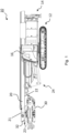
- FIG. 1 a preferred embodiment of the working device 10 according to the invention is shown in a side view.
- the embodiment discussed here is a working device 10 with an attachment tool 30 designed as a vibrator, more precisely an upright vibrator, although of course any other attachment tool can also be used.
- the working device 10 comprises a base device with a mobile undercarriage 12, which in this embodiment has a crawler chassis.
- a superstructure 14 is mounted on the undercarriage 12 so as to be rotatable about a vertical axis.
- the Upper carriage 14 comprises a driver's cab 16 and a device for supporting the working machine (visible in the figure at the rear of the upper carriage 14).
- a leader 20 is connected to the upper carriage 14 via a leader kinematics 24.
- the leader 20 can be moved between a Figure 1 shown transport position, in which the leader 20 is mounted essentially horizontally, and an operating position.
- the operating position includes in particular a vertical alignment of the leader 20, but can also include any inclined positions of the leader 20 that are made possible by the leader kinematics 24.
- the pile driving material which can be grasped with a pair of tongs of the vibrator 30, can be introduced into the ground not only vertically, but also at a certain angle to the vertical.
- the leader 20 has a front side 21 which faces away from the upper carriage 14 and in the transport position, as shown in the Figure 1 can be seen, points upwards.
- the working device comprises an attachment 30, in the form of a vertical vibrator.
- the attachment 30 is in an operating position on the front 21 of the leader 20 and can be moved in particular via a Figure 1 not shown movement mechanism along the leader 20.
- a downward force in the operating position of the leader 20
- a downward force can be applied to the vibrator 30 via the movement mechanism in order to support the vibrating of the material to be vibrated into the ground.
- the vibrator 30 can be mounted in the operating position either directly or via an attachment slide on the leader 20.
- an embodiment without such a carriage is shown.
- the vibrator 30 has first connecting means for connection to the leader 20.
- the leader 20 preferably has guide rails on which the vibrator 30 is mounted in the operating position via corresponding guide rail mounts 32.
- the guide rail mounts 32 can represent or comprise the first connecting means mentioned. Any position of the vibrator 30 on the front side 21 of the leader 20 along the longitudinal axis of the leader 20 can be regarded as an operating position.
- the Figure 1 shows the transport position of the working device 10, in which the leader 20 is folded back over the leader kinematics 24 and the lower end of the leader 20 protrudes forwards over the upper carriage 14. In this position, the working device 10 can be transported, for example on a transport vehicle (not shown). If the vibrator 30 were to remain in its operating position on the front 21 of the leader 20, it would be in the Figure 1 above the leader 20 and would significantly increase the transport height of the attachment 10.
- the invention provides a way of removing the vibrator 30 from the front 21 of the leader 20 and storing it in a transport position that is spatially separate from the operating position in a space-saving manner.
- the transport position of the vibrator 30 is on the back 22 of the leader 20 (which is opposite the leader front 21), i.e. the vibrator 30 is arranged in the transport position on the leader rear 22 between the leader 20 and the ground. This allows the vibrator 30 to be transported together with the leader 20 and the base device without increasing the transport dimensions.
- the operator has a clear view to the front from the driver's cab 16, so that the work device 10 can also be moved independently.
- the leader 20 In order to store the vibrator 30 on the leader rear side 22, the leader 20 has corresponding support means 23, which are arranged in the Figure 1 are covered by the vibrator 30.
- the receiving means 23 can be located on the rear side 22 of the leader.
- the vibrator 30 can either have its own (second) connecting means for connection to the receiving means 23 of the leader 20.
- the first connecting means in the Figure 1 represented by the guide rail holders 32 of the vibrator 30 for connection to the receiving means 23 of the leader 20.
Landscapes
- Engineering & Computer Science (AREA)
- Mining & Mineral Resources (AREA)
- Life Sciences & Earth Sciences (AREA)
- Geology (AREA)
- General Life Sciences & Earth Sciences (AREA)
- Geochemistry & Mineralogy (AREA)
- Fluid Mechanics (AREA)
- Environmental & Geological Engineering (AREA)
- Physics & Mathematics (AREA)
- Civil Engineering (AREA)
- General Engineering & Computer Science (AREA)
- Structural Engineering (AREA)
- Mechanical Engineering (AREA)
- Paleontology (AREA)
- Earth Drilling (AREA)
- Placing Or Removing Of Piles Or Sheet Piles, Or Accessories Thereof (AREA)
Claims (15)
- Appareil de travail (10), notamment appareil mobile de forage rotatif, de battage ou de perçage, avec un châssis inférieur déplaçable (12), un châssis supérieur (14), un mât (20) monté sur le châssis supérieur (14) et un accessoire (30), le mât (20) étant monté pivotant sur le châssis supérieur (14) par l'intermédiaire d'une cinématique de mât (24) et l'accessoire (30) pouvant être monté dans une position de fonctionnement sur un côté avant (21) du mât (20) détourné du châssis supérieur (14), l'accessoire (30) pouvant être retiré du côté avant du mât (20),
caractérisé en ce que
le mât (20) comprend des moyens de réception (23), par l'intermédiaire desquels l'accessoire (30) peut être monté pour le transport sur un côté arrière (22) du mât (20) tourné vers le châssis supérieur (14) dans une position de transport, de telle sorte que l'accessoire (30) est agencé dans la position de transport sur le côté arrière (22) du mât (20) entre le mât (20) et le sol. - Appareil de travail (10) selon la revendication 1, dans lequel le mât (20) comprend un guide de mât sur lequel l'accessoire (30) peut être monté de manière coulissante, notamment de manière coulissante le long d'un axe longitudinal du mât (20), le guide de mât comprenant de préférence au moins un rail de guidage s'étendant parallèlement à l'axe longitudinal du mât (20), qui est agencé sur le côté avant (21) du mât (20) ou latéralement sur le mât (20).
- Appareil de travail (10) selon la revendication 1 ou 2, dans lequel la cinématique de mât (24) est configurée pour faire pivoter le mât (20) dans un plan de pivotement vertical par rapport au châssis supérieur (14), notamment par l'intermédiaire d'un ou de plusieurs vérins hydrauliques de pivotement, le mât (20) étant orienté horizontalement ou essentiellement horizontalement dans une position de transport et le côté avant (21) du mât (20) pointant vers le haut.
- Appareil de travail (10) selon la revendication précédente, dans lequel l'accessoire (30) est agencé devant le châssis supérieur (14) dans la position de transport dans la direction de déplacement.
- Appareil de travail (10) selon l'une quelconque des revendications précédentes, dans lequel les moyens de réception (23) sont agencés dans une zone d'extrémité du mât (20), notamment dans la zone d'une extrémité qui forme l'extrémité inférieure du mât (20) dans le cas d'un mât (20) dressé verticalement.
- Appareil de travail (10) selon l'une quelconque des revendications précédentes, dans lequel les moyens de réception (23) sont configurés pour fixer l'accessoire (30) de manière immobile sur le mât (20) dans la position de transport, les moyens de réception (23) comprenant de préférence des logements de boulon pour réaliser une liaison par boulon.
- Appareil de travail (10) selon l'une quelconque des revendications précédentes, dans lequel les moyens de réception (23) sont agencés sur le côté arrière (22) et/ou latéralement sur le mât (20).
- Appareil de travail (10) selon l'une quelconque des revendications précédentes, dans lequel le mât (20) est configuré sous forme divisible et/ou rabattable et les moyens de réception (23) se trouvent sur une partie de base du mât (20) reliée en permanence à la cinématique de mât (24).
- Appareil de travail (10) selon l'une quelconque des revendications précédentes, dans lequel l'accessoire (30) peut être monté sur le côté avant (21) du mât (20) par l'intermédiaire d'un chariot d'accessoire, et l'accessoire (30) et le chariot d'accessoire comprennent chacun des moyens de liaison pour réaliser une liaison amovible entre l'accessoire (30) et le chariot d'accessoire, les moyens de liaison comprenant de préférence des logements de boulon pour réaliser une liaison par boulon et/ou des éléments d'accrochage pour réaliser une liaison par accrochage.
- Appareil de travail (10) selon la revendication précédente, dans lequel le chariot d'accessoire est monté sur le mât (20) de manière coulissante, notamment de manière coulissante par l'intermédiaire d'un guide de mât le long d'un axe longitudinal du mât (20).
- Appareil de travail (10) selon l'une quelconque des deux revendications précédentes, dans lequel l'accessoire (30) peut être relié aux moyens de réception (23) du mât (20) directement et/ou par l'intermédiaire du chariot d'accessoire.
- Appareil de travail (10) selon l'une quelconque des revendications précédentes, dans lequel l'accessoire (30) comprend un mécanisme de forage, un mécanisme de forage à double tête, un marteau hydraulique ou un vibreur, notamment un vibreur sur chant ou un vibreur à ceinture.
- Mât pour un appareil de travail (10) selon l'une quelconque des revendications précédentes, l'accessoire (30) pouvant être retiré du côté avant (21) du mât (20), le mât (20) comprenant des moyens de réception (23), par l'intermédiaire desquels l'accessoire (30) de l'appareil de travail (10) peut être monté pour le transport sur un côté arrière (22) du mât (20) tourné vers le châssis supérieur (14) dans une position de transport, de telle sorte que l'accessoire (30) est agencé dans la position de transport sur le côté arrière (22) du mât (20) entre le mât (20) et le sol.
- Ensemble d'un mât (20) selon la revendication précédente et d'un accessoire (30) qui peut être monté dans une position de fonctionnement sur le côté avant (21) du mât (20) et dans une position de transport par l'intermédiaire des moyens de réception supplémentaires (23) sur le côté arrière (22) du mât (20).
- Ensemble selon la revendication précédente, dans lequel l'accessoire (30) comprend un mécanisme de forage, un mécanisme de forage à double tête, un marteau hydraulique ou un vibreur, notamment un vibreur sur chant ou un vibreur à ceinture.
Applications Claiming Priority (1)
| Application Number | Priority Date | Filing Date | Title |
|---|---|---|---|
| DE202022104322.1U DE202022104322U1 (de) | 2022-07-29 | 2022-07-29 | Arbeitsgerät mit Mäkler |
Publications (2)
| Publication Number | Publication Date |
|---|---|
| EP4311909A1 EP4311909A1 (fr) | 2024-01-31 |
| EP4311909B1 true EP4311909B1 (fr) | 2025-02-26 |
Family
ID=87377737
Family Applications (1)
| Application Number | Title | Priority Date | Filing Date |
|---|---|---|---|
| EP23185834.1A Active EP4311909B1 (fr) | 2022-07-29 | 2023-07-17 | Appareil de travail avec mêche |
Country Status (3)
| Country | Link |
|---|---|
| US (1) | US12305509B2 (fr) |
| EP (1) | EP4311909B1 (fr) |
| DE (1) | DE202022104322U1 (fr) |
Family Cites Families (7)
| Publication number | Priority date | Publication date | Assignee | Title |
|---|---|---|---|---|
| JPS584025A (ja) * | 1981-06-30 | 1983-01-11 | Nippon Sharyo Seizo Kaisha Ltd | 杭打機のフロントアタツチメント格納方法及びその装置 |
| DE3610814C2 (de) * | 1986-04-01 | 1997-07-24 | Delmag Maschinenfabrik | Fahrbares Bohr-, Ramm- oder dergleichen Gerät |
| DE4436264C1 (de) * | 1994-10-11 | 1995-11-30 | Wirth Co Kg Masch Bohr | Bohrmast |
| DE19520129A1 (de) * | 1995-06-01 | 1996-12-05 | Klaus Obermann Gmbh | Universal-Baugerät |
| EP1862636B1 (fr) * | 2006-06-02 | 2011-01-05 | BAUER Maschinen GmbH | Engin de travaux publics, specialement un dispositif de forage |
| FI2902582T4 (fi) * | 2014-01-29 | 2023-03-27 | Mastokokoonpano ja menetelmä työkoneyksikön liittämiseksi mastokokoonpanon mastovaunuun | |
| US11414929B2 (en) * | 2020-03-09 | 2022-08-16 | Watson, Incorporated | Drilling apparatus and related method |
-
2022
- 2022-07-29 DE DE202022104322.1U patent/DE202022104322U1/de active Active
-
2023
- 2023-07-17 EP EP23185834.1A patent/EP4311909B1/fr active Active
- 2023-07-28 US US18/361,623 patent/US12305509B2/en active Active
Also Published As
| Publication number | Publication date |
|---|---|
| US12305509B2 (en) | 2025-05-20 |
| EP4311909A1 (fr) | 2024-01-31 |
| US20240035340A1 (en) | 2024-02-01 |
| DE202022104322U1 (de) | 2023-10-31 |
Similar Documents
| Publication | Publication Date | Title |
|---|---|---|
| DE19631042C5 (de) | Straßenbaumaschinen zum Bearbeiten von Fahrbahnen | |
| EP1862636B1 (fr) | Engin de travaux publics, specialement un dispositif de forage | |
| DE3024664A1 (de) | Landwirtschaftliches mehrzweckfahrzeug | |
| DE112016000646T5 (de) | Bewegungsvorrichtung für gegengewicht | |
| DE2559293A1 (de) | Vorrichtung zum leicht loesbaren befestigen von last aufnehmenden einrichtungen an last hebenden einrichtungen | |
| DE2406590A1 (de) | Kran, insbesondere autokran mit einem teleskopausleger und einem spitzenausleger und verfahren zur befestigung des spitzenauslegers am teleskopausleger | |
| DE2542305C3 (de) | Bodenaushubgerät | |
| DE4316364A1 (de) | Mehrzweck-Arbeits-Fahrzeug | |
| EP1657400B1 (fr) | Appareil de construction | |
| DE69922668T2 (de) | Auslegeranordnung für eine gesteinbohreinheit | |
| DE2739537A1 (de) | Schwenkgabelanordnung fuer verladeausruestungen | |
| EP3425123A1 (fr) | Console d'un engin | |
| EP1621682A2 (fr) | Appareil de transbordement. | |
| EP0065118A2 (fr) | Excavatrice | |
| DE1608474B1 (de) | Fahrbare Bohrvorrichtung | |
| DE3932555C2 (fr) | ||
| DE102017116716A1 (de) | Bearbeitungsanlage für Flugzeugstrukturbauteile | |
| EP1068780A1 (fr) | Dispositif pivotable d'accouplement d'outil pour véhicule motorisé | |
| EP1655450B1 (fr) | Appareil de forage | |
| EP4311909A1 (fr) | Appareil de travail avec mêche | |
| DE29718149U1 (de) | Fahrbares Arbeitsgerät | |
| DE60008967T2 (de) | Montagevorrichtung | |
| EP2557064B1 (fr) | Appareil de construction | |
| DE3610814C2 (de) | Fahrbares Bohr-, Ramm- oder dergleichen Gerät | |
| EP4083327A1 (fr) | Engin de génie civil |
Legal Events
| Date | Code | Title | Description |
|---|---|---|---|
| PUAI | Public reference made under article 153(3) epc to a published international application that has entered the european phase |
Free format text: ORIGINAL CODE: 0009012 |
|
| STAA | Information on the status of an ep patent application or granted ep patent |
Free format text: STATUS: THE APPLICATION HAS BEEN PUBLISHED |
|
| AK | Designated contracting states |
Kind code of ref document: A1 Designated state(s): AL AT BE BG CH CY CZ DE DK EE ES FI FR GB GR HR HU IE IS IT LI LT LU LV MC ME MK MT NL NO PL PT RO RS SE SI SK SM TR |
|
| STAA | Information on the status of an ep patent application or granted ep patent |
Free format text: STATUS: REQUEST FOR EXAMINATION WAS MADE |
|
| 17P | Request for examination filed |
Effective date: 20240529 |
|
| GRAP | Despatch of communication of intention to grant a patent |
Free format text: ORIGINAL CODE: EPIDOSNIGR1 |
|
| STAA | Information on the status of an ep patent application or granted ep patent |
Free format text: STATUS: GRANT OF PATENT IS INTENDED |
|
| RIC1 | Information provided on ipc code assigned before grant |
Ipc: E02D 7/00 20060101ALI20240920BHEP Ipc: E02D 7/16 20060101ALI20240920BHEP Ipc: E21B 7/02 20060101AFI20240920BHEP |
|
| INTG | Intention to grant announced |
Effective date: 20241008 |
|
| GRAS | Grant fee paid |
Free format text: ORIGINAL CODE: EPIDOSNIGR3 |
|
| GRAA | (expected) grant |
Free format text: ORIGINAL CODE: 0009210 |
|
| STAA | Information on the status of an ep patent application or granted ep patent |
Free format text: STATUS: THE PATENT HAS BEEN GRANTED |
|
| AK | Designated contracting states |
Kind code of ref document: B1 Designated state(s): AL AT BE BG CH CY CZ DE DK EE ES FI FR GB GR HR HU IE IS IT LI LT LU LV MC ME MK MT NL NO PL PT RO RS SE SI SK SM TR |
|
| P01 | Opt-out of the competence of the unified patent court (upc) registered |
Free format text: CASE NUMBER: APP_3073/2025 Effective date: 20250120 |
|
| REG | Reference to a national code |
Ref country code: GB Ref legal event code: FG4D Free format text: NOT ENGLISH |
|
| REG | Reference to a national code |
Ref country code: CH Ref legal event code: EP |
|
| REG | Reference to a national code |
Ref country code: NL Ref legal event code: FP |
|
| REG | Reference to a national code |
Ref country code: DE Ref legal event code: R096 Ref document number: 502023000610 Country of ref document: DE |
|
| REG | Reference to a national code |
Ref country code: IE Ref legal event code: FG4D Free format text: LANGUAGE OF EP DOCUMENT: GERMAN |
|
| PG25 | Lapsed in a contracting state [announced via postgrant information from national office to epo] |
Ref country code: RS Free format text: LAPSE BECAUSE OF FAILURE TO SUBMIT A TRANSLATION OF THE DESCRIPTION OR TO PAY THE FEE WITHIN THE PRESCRIBED TIME-LIMIT Effective date: 20250526 |
|
| PG25 | Lapsed in a contracting state [announced via postgrant information from national office to epo] |
Ref country code: FI Free format text: LAPSE BECAUSE OF FAILURE TO SUBMIT A TRANSLATION OF THE DESCRIPTION OR TO PAY THE FEE WITHIN THE PRESCRIBED TIME-LIMIT Effective date: 20250226 |
|
| PG25 | Lapsed in a contracting state [announced via postgrant information from national office to epo] |
Ref country code: PL Free format text: LAPSE BECAUSE OF FAILURE TO SUBMIT A TRANSLATION OF THE DESCRIPTION OR TO PAY THE FEE WITHIN THE PRESCRIBED TIME-LIMIT Effective date: 20250226 |
|
| PG25 | Lapsed in a contracting state [announced via postgrant information from national office to epo] |
Ref country code: ES Free format text: LAPSE BECAUSE OF FAILURE TO SUBMIT A TRANSLATION OF THE DESCRIPTION OR TO PAY THE FEE WITHIN THE PRESCRIBED TIME-LIMIT Effective date: 20250226 |
|
| REG | Reference to a national code |
Ref country code: LT Ref legal event code: MG9D |
|
| PG25 | Lapsed in a contracting state [announced via postgrant information from national office to epo] |
Ref country code: NO Free format text: LAPSE BECAUSE OF FAILURE TO SUBMIT A TRANSLATION OF THE DESCRIPTION OR TO PAY THE FEE WITHIN THE PRESCRIBED TIME-LIMIT Effective date: 20250526 Ref country code: IS Free format text: LAPSE BECAUSE OF FAILURE TO SUBMIT A TRANSLATION OF THE DESCRIPTION OR TO PAY THE FEE WITHIN THE PRESCRIBED TIME-LIMIT Effective date: 20250626 |
|
| PG25 | Lapsed in a contracting state [announced via postgrant information from national office to epo] |
Ref country code: HR Free format text: LAPSE BECAUSE OF FAILURE TO SUBMIT A TRANSLATION OF THE DESCRIPTION OR TO PAY THE FEE WITHIN THE PRESCRIBED TIME-LIMIT Effective date: 20250226 |
|
| PG25 | Lapsed in a contracting state [announced via postgrant information from national office to epo] |
Ref country code: PT Free format text: LAPSE BECAUSE OF FAILURE TO SUBMIT A TRANSLATION OF THE DESCRIPTION OR TO PAY THE FEE WITHIN THE PRESCRIBED TIME-LIMIT Effective date: 20250626 Ref country code: LV Free format text: LAPSE BECAUSE OF FAILURE TO SUBMIT A TRANSLATION OF THE DESCRIPTION OR TO PAY THE FEE WITHIN THE PRESCRIBED TIME-LIMIT Effective date: 20250226 |
|
| PG25 | Lapsed in a contracting state [announced via postgrant information from national office to epo] |
Ref country code: BG Free format text: LAPSE BECAUSE OF FAILURE TO SUBMIT A TRANSLATION OF THE DESCRIPTION OR TO PAY THE FEE WITHIN THE PRESCRIBED TIME-LIMIT Effective date: 20250226 Ref country code: GR Free format text: LAPSE BECAUSE OF FAILURE TO SUBMIT A TRANSLATION OF THE DESCRIPTION OR TO PAY THE FEE WITHIN THE PRESCRIBED TIME-LIMIT Effective date: 20250527 |
|
| PG25 | Lapsed in a contracting state [announced via postgrant information from national office to epo] |
Ref country code: SE Free format text: LAPSE BECAUSE OF FAILURE TO SUBMIT A TRANSLATION OF THE DESCRIPTION OR TO PAY THE FEE WITHIN THE PRESCRIBED TIME-LIMIT Effective date: 20250226 |
|
| PG25 | Lapsed in a contracting state [announced via postgrant information from national office to epo] |
Ref country code: SM Free format text: LAPSE BECAUSE OF FAILURE TO SUBMIT A TRANSLATION OF THE DESCRIPTION OR TO PAY THE FEE WITHIN THE PRESCRIBED TIME-LIMIT Effective date: 20250226 |
|
| PG25 | Lapsed in a contracting state [announced via postgrant information from national office to epo] |
Ref country code: DK Free format text: LAPSE BECAUSE OF FAILURE TO SUBMIT A TRANSLATION OF THE DESCRIPTION OR TO PAY THE FEE WITHIN THE PRESCRIBED TIME-LIMIT Effective date: 20250226 |
|
| PGFP | Annual fee paid to national office [announced via postgrant information from national office to epo] |
Ref country code: DE Payment date: 20250730 Year of fee payment: 3 |
|
| PGFP | Annual fee paid to national office [announced via postgrant information from national office to epo] |
Ref country code: IT Payment date: 20250731 Year of fee payment: 3 |
|
| PGFP | Annual fee paid to national office [announced via postgrant information from national office to epo] |
Ref country code: FR Payment date: 20250729 Year of fee payment: 3 Ref country code: AT Payment date: 20251020 Year of fee payment: 3 |
|
| PG25 | Lapsed in a contracting state [announced via postgrant information from national office to epo] |
Ref country code: CZ Free format text: LAPSE BECAUSE OF FAILURE TO SUBMIT A TRANSLATION OF THE DESCRIPTION OR TO PAY THE FEE WITHIN THE PRESCRIBED TIME-LIMIT Effective date: 20250226 Ref country code: EE Free format text: LAPSE BECAUSE OF FAILURE TO SUBMIT A TRANSLATION OF THE DESCRIPTION OR TO PAY THE FEE WITHIN THE PRESCRIBED TIME-LIMIT Effective date: 20250226 |
|
| PG25 | Lapsed in a contracting state [announced via postgrant information from national office to epo] |
Ref country code: RO Free format text: LAPSE BECAUSE OF FAILURE TO SUBMIT A TRANSLATION OF THE DESCRIPTION OR TO PAY THE FEE WITHIN THE PRESCRIBED TIME-LIMIT Effective date: 20250226 |
|
| PG25 | Lapsed in a contracting state [announced via postgrant information from national office to epo] |
Ref country code: SK Free format text: LAPSE BECAUSE OF FAILURE TO SUBMIT A TRANSLATION OF THE DESCRIPTION OR TO PAY THE FEE WITHIN THE PRESCRIBED TIME-LIMIT Effective date: 20250226 |
|
| REG | Reference to a national code |
Ref country code: DE Ref legal event code: R097 Ref document number: 502023000610 Country of ref document: DE |
|
| PLBE | No opposition filed within time limit |
Free format text: ORIGINAL CODE: 0009261 |
|
| STAA | Information on the status of an ep patent application or granted ep patent |
Free format text: STATUS: NO OPPOSITION FILED WITHIN TIME LIMIT |
|
| 26N | No opposition filed |
Effective date: 20251127 |
|
| PG25 | Lapsed in a contracting state [announced via postgrant information from national office to epo] |
Ref country code: LU Free format text: LAPSE BECAUSE OF NON-PAYMENT OF DUE FEES Effective date: 20250717 |
|
| REG | Reference to a national code |
Ref country code: BE Ref legal event code: MM Effective date: 20250731 |
|
| PG25 | Lapsed in a contracting state [announced via postgrant information from national office to epo] |
Ref country code: BE Free format text: LAPSE BECAUSE OF NON-PAYMENT OF DUE FEES Effective date: 20250731 |
|
| PG25 | Lapsed in a contracting state [announced via postgrant information from national office to epo] |
Ref country code: LT Free format text: LAPSE BECAUSE OF FAILURE TO SUBMIT A TRANSLATION OF THE DESCRIPTION OR TO PAY THE FEE WITHIN THE PRESCRIBED TIME-LIMIT Effective date: 20250226 |
|
| PG25 | Lapsed in a contracting state [announced via postgrant information from national office to epo] |
Ref country code: IE Free format text: LAPSE BECAUSE OF NON-PAYMENT OF DUE FEES Effective date: 20250717 |
|
| PG25 | Lapsed in a contracting state [announced via postgrant information from national office to epo] |
Ref country code: MC Free format text: LAPSE BECAUSE OF FAILURE TO SUBMIT A TRANSLATION OF THE DESCRIPTION OR TO PAY THE FEE WITHIN THE PRESCRIBED TIME-LIMIT Effective date: 20250226 |
|
| PG25 | Lapsed in a contracting state [announced via postgrant information from national office to epo] |
Ref country code: CY Free format text: LAPSE BECAUSE OF FAILURE TO SUBMIT A TRANSLATION OF THE DESCRIPTION OR TO PAY THE FEE WITHIN THE PRESCRIBED TIME-LIMIT Effective date: 20250226 |