EP0814958B1 - Vorrichtung zum verhindern von fehlern während der kaschierung von materialien - Google Patents
Vorrichtung zum verhindern von fehlern während der kaschierung von materialien Download PDFInfo
- Publication number
- EP0814958B1 EP0814958B1 EP96905376A EP96905376A EP0814958B1 EP 0814958 B1 EP0814958 B1 EP 0814958B1 EP 96905376 A EP96905376 A EP 96905376A EP 96905376 A EP96905376 A EP 96905376A EP 0814958 B1 EP0814958 B1 EP 0814958B1
- Authority
- EP
- European Patent Office
- Prior art keywords
- laminate
- laminating
- materials
- guide
- laminating member
- Prior art date
- Legal status (The legal status is an assumption and is not a legal conclusion. Google has not performed a legal analysis and makes no representation as to the accuracy of the status listed.)
- Expired - Lifetime
Links
- 239000000463 material Substances 0.000 title claims description 84
- 230000007547 defect Effects 0.000 title description 12
- 238000003475 lamination Methods 0.000 title description 9
- 238000010030 laminating Methods 0.000 claims description 154
- 238000010438 heat treatment Methods 0.000 claims description 18
- 238000000034 method Methods 0.000 description 9
- 238000009823 thermal lamination Methods 0.000 description 9
- 238000013459 approach Methods 0.000 description 5
- 239000002783 friction material Substances 0.000 description 5
- 235000012773 waffles Nutrition 0.000 description 5
- 230000037303 wrinkles Effects 0.000 description 4
- 239000003086 colorant Substances 0.000 description 3
- 238000012546 transfer Methods 0.000 description 3
- AZDRQVAHHNSJOQ-UHFFFAOYSA-N alumane Chemical group [AlH3] AZDRQVAHHNSJOQ-UHFFFAOYSA-N 0.000 description 2
- 239000002648 laminated material Substances 0.000 description 2
- 229910052751 metal Inorganic materials 0.000 description 2
- 239000002184 metal Substances 0.000 description 2
- 239000004033 plastic Substances 0.000 description 2
- 241000191291 Abies alba Species 0.000 description 1
- 239000000853 adhesive Substances 0.000 description 1
- 230000001070 adhesive effect Effects 0.000 description 1
- 239000011248 coating agent Substances 0.000 description 1
- 238000000576 coating method Methods 0.000 description 1
- 238000010276 construction Methods 0.000 description 1
- 238000005562 fading Methods 0.000 description 1
- 230000005484 gravity Effects 0.000 description 1
- 238000003780 insertion Methods 0.000 description 1
- 230000037431 insertion Effects 0.000 description 1
- 238000013021 overheating Methods 0.000 description 1
- 229920006267 polyester film Polymers 0.000 description 1
- 238000003825 pressing Methods 0.000 description 1
- 238000006748 scratching Methods 0.000 description 1
- 230000002393 scratching effect Effects 0.000 description 1
- 239000004447 silicone coating Substances 0.000 description 1
Images

Classifications
-
- B—PERFORMING OPERATIONS; TRANSPORTING
- B32—LAYERED PRODUCTS
- B32B—LAYERED PRODUCTS, i.e. PRODUCTS BUILT-UP OF STRATA OF FLAT OR NON-FLAT, e.g. CELLULAR OR HONEYCOMB, FORM
- B32B38/00—Ancillary operations in connection with laminating processes
- B32B38/18—Handling of layers or the laminate
- B32B38/1866—Handling of layers or the laminate conforming the layers or laminate to a convex or concave profile
-
- B—PERFORMING OPERATIONS; TRANSPORTING
- B65—CONVEYING; PACKING; STORING; HANDLING THIN OR FILAMENTARY MATERIAL
- B65H—HANDLING THIN OR FILAMENTARY MATERIAL, e.g. SHEETS, WEBS, CABLES
- B65H23/00—Registering, tensioning, smoothing or guiding webs
- B65H23/04—Registering, tensioning, smoothing or guiding webs longitudinally
- B65H23/26—Registering, tensioning, smoothing or guiding webs longitudinally by transverse stationary or adjustable bars or rollers
-
- B—PERFORMING OPERATIONS; TRANSPORTING
- B65—CONVEYING; PACKING; STORING; HANDLING THIN OR FILAMENTARY MATERIAL
- B65H—HANDLING THIN OR FILAMENTARY MATERIAL, e.g. SHEETS, WEBS, CABLES
- B65H23/00—Registering, tensioning, smoothing or guiding webs
- B65H23/04—Registering, tensioning, smoothing or guiding webs longitudinally
- B65H23/34—Apparatus for taking-out curl from webs
-
- Y—GENERAL TAGGING OF NEW TECHNOLOGICAL DEVELOPMENTS; GENERAL TAGGING OF CROSS-SECTIONAL TECHNOLOGIES SPANNING OVER SEVERAL SECTIONS OF THE IPC; TECHNICAL SUBJECTS COVERED BY FORMER USPC CROSS-REFERENCE ART COLLECTIONS [XRACs] AND DIGESTS
- Y10—TECHNICAL SUBJECTS COVERED BY FORMER USPC
- Y10T—TECHNICAL SUBJECTS COVERED BY FORMER US CLASSIFICATION
- Y10T156/00—Adhesive bonding and miscellaneous chemical manufacture
- Y10T156/17—Surface bonding means and/or assemblymeans with work feeding or handling means
- Y10T156/1702—For plural parts or plural areas of single part
- Y10T156/1712—Indefinite or running length work
- Y10T156/1741—Progressive continuous bonding press [e.g., roll couples]
Definitions
- the present invention is directed generally to an apparatus for preventing defects, such as wrinkles and ripples, in materials being laminated.
- the present invention can be directed to an apparatus for preventing or removing defects, such as wrinkles and ripples, in proofing materials when these materials are laminated together.
- Thermal lamination involves the application of heat and pressure to two or more materials being laminated. These materials can be in sheet or web form.
- One goal when laminating is to apply sufficient heat and pressure to complete the lamination. Ideally, this goal should be accomplished without causing excessive shrinkage or stretch, and wrinkles, ripples, or curl.
- Waves are a type of ripple which angle diagonally along the length of the materials and have consequently been referred to as "Christmas Tree" waves.
- Waffle is another defect made up of numerous criss-crossing ripples giving a guilded appearance to the affected area.
- Color density loss is the undesirable fading and/or inconsistency of colors within the laminate.
- US-A-4 862 409 describes a thermal lamination process which automatically adjusts the distance of contact of two films with the heat roll. This allows for a constant amount of heat to be transferred to the films even when the lamination linespeed varies. The constant amount of heat is noted to provide sufficient bend strength without overheating which can cause creasing and clouding of the films.
- This invention is noted by the inventors to be particularly useful just after start-up of the laminating process or just before stopping the laminating process. But, this approach has not satisfactorily solved the wrinkling problem, nor any of the other previously mentioned problems.
- US-A-4 946 640 describes an apparatus having a guide member surface and the application of a vacuum to the laminate materials.
- the vacuum creates a generally uniform drag force across the width of the laminate materials. This drag force is noted by inventors to eliminate wrinkles which form naturally at the guide member surface.
- this approach is relatively complex and expensive with the additional cost of including and maintaining the vacuum-providing hardware.
- Graphic arts materials can be especially vulnerable to wave, waffle, and color density loss.
- the lamination of certain graphic arts materials commonly involves transferring four colors from four film-based color sheets (cyan, magenta, yellow, and black) to a paper base sheet.
- the first color sheet is laminated to the base sheet to create a proof, which is then exposed to create a first color image.
- the color sheet backing is then stripped off leaving at least a portion of the colored material from the color sheet behind on the base sheet.
- the remaining three colors can be transferred to the base sheet and exposed in the same manner.
- the four-color image created on the base sheet can instead be made on a transfer sheet, and then, can be ultimately transferred from the transfer sheet to a base sheet.
- Color sheets and transfer sheets commonly include a polyester film backing, wherein base sheets commonly include a paper backing.
- One embodiment of the present invention includes an apparatus for thermally laminating materials to form a laminate and for guiding the laminate.
- This apparatus includes a first laminating member and a first heating means for heating the first laminating member to a first temperature.
- a second laminating member is positioned relative to the first laminating member to allow the materials to pass between the first and second laminating members such that the materials are heated to a laminating temperature and such that the first and second laminating members can apply pressure to the materials to form the laminate.
- a first guide is positioned relative to the first and second laminating members to enable the first guide to turn the laminate in a first direction away from the first laminating member.
- a second guide is positioned relative to the first guide to enable the second guide to turn the laminate in a second direction. Turning the laminate from the first direction to the second direction reverses the curvature.
- Another embodiment includes an apparatus for thermally laminating materials to form a laminate and for guiding the laminate.
- This apparatus includes means for heating the materials from a first material temperature to a second material temperature. Means are also included for applying pressure to the materials.
- the pressure-applying means is operatively coupled to the heating means such that pressure is applied to the materials when the heating means has heated the materials to above the first temperature to form the laminate.
- the pressure-applying means is positioned such that the laminate travels in an original direction when pressure is applied thereto.
- a first guide is positioned relative to the heating means and the pressure-applying means to enable the first guide to turn the laminate in a first direction which is different from the original direction.
- a second guide is positioned relative to the first guide to enable the second guide to turn the laminate in a second direction. The second direction is different from the first direction and is similar to the original direction.
- Another embodiment includes an apparatus for thermally laminating materials to form a laminate and for guiding the laminate.
- This apparatus includes a heated upper roller and a heated lower roller positioned lower than the upper roller. The materials can travel between the heated upper and lower rollers in an original direction such that the heated upper and lower rollers can apply pressure and heat to the materials to form the laminate.
- the heated lower roller is heated to a temperature which is lower than that the heated upper roller.
- a first guide is positioned relative to the upper and lower rollers to enable the first guide to turn the laminate in a first direction downwardly away from the upper roller and toward the lower roller.
- a second guide is positioned relative to the first guide to enable the second guide to turn the laminate in a second direction away from the lower roller.
- Another embodiment includes an apparatus for thermally laminating materials to form a laminate and for guiding the laminate.
- This apparatus includes a frame and a laminating assembly supported by the frame.
- the frame can include an assembly surface across which the materials can rest.
- a first laminating member is positioned adjacent to the assembly surface. Means are included for heating the first laminating member to a first temperature.
- a second laminating member is positioned relative to the assembly surface and the first laminating member such that the materials can be moved from the assembly surface and passed between the first and second laminating members and such that heat and pressure are applied to the materials when passing between the first and second laminating members to form the laminate.
- a guiding assembly is supported by the frame and positioned relative to the laminating assembly to receive and guide the laminate from the laminating assembly.
- the guiding assembly includes a first guide positioned relative to the first and second laminating members to enable the first guide to turn the laminate in a first direction away from the first laminating member. Turning the laminate in the first direction causes the laminate to have a curvature. A second guide is positioned relative to the first guide to enable the second guide to turn the laminate in a second direction. Turning the laminate from the first direction to the second direction reverses the curvature.
- a method for thermally laminating materials together to form a laminate and for guiding the laminate includes heating a first laminating member to a first temperature. Another step is heating a second laminating member to a second temperature, the second temperature being lower than the first temperature. Another step includes passing the materials between the first and second laminating members. The second laminating member is positioned relative to the first laminating member such that the first and second laminating members can apply heat and pressure to the materials to form the laminate. Another step includes turning the laminate exiting from between the first and second laminating members in a first direction away from the first laminating member. Turning the laminate in the first direction causes the laminate to have a curvature. Another step includes turning the laminate in a second direction. Turning the laminate from the first direction to the second direction reverses the curvature.
- a method for thermally laminating a first sheet of proofing material to a second sheet of proofing material to form a laminate and for turning the laminate includes heating a first laminating member to a first temperature. Another step includes heating a second laminating member to a second temperature, the second temperature being lower than the first temperature. Another step includes passing the first and second sheets of proofing material between the first laminating member and the second laminating member. The second laminating member is positioned relative to the first laminating member such that heat and pressure are applied to the first and second sheets of proofing material to form the laminate when the materials are passed between the first and second laminating members.
- Another step includes turning the laminate exiting from between the first and second laminating members in a first direction away from the first laminating member causing the laminate to have a curvature.
- Another step includes turning the laminate in a second direction. Turning the laminate from the first direction to the second direction reverses the curvature.
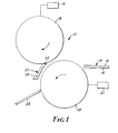
- materials 10 are shown as being inserted in a thermal lamination apparatus 12.
- the materials 10 can be inserted into the thermal lamination apparatus 12 by hand or by drive rollers (not shown).
- the materials 10 are shown as including two sheets of proofing materials, a base sheet 14 and a color sheet 16. Other types of materials can be similarly laminated.
- the thermal lamination apparatus 12 includes a first laminating member 18, a second laminating member 20, a first guide 22, and a second guide 24.
- the first laminating member 18 is shown as a first roller although other forms of laminating members could be used, for example, a series of smaller rollers or one or more belts.
- the second laminating member 20 is shown as a second roller, although similar alternative embodiments are possible.
- the first and second laminating members 18, 20 can be heated to the same or different temperatures and can be driven to transport the materials 10.
- the first and second laminating members 18, 20 can each be made of a polymeric cylindrical core, a metallic cylindrical core covered with a polymeric coating, or a metallic cylinder, as is known in the art.
- the first laminating member 18 can include an aluminum core covered with a 5-millimeter silicone coating
- the second laminating member 20 include an aluminum core covered with a low-adhesion surface, such as SilverStoneTM.
- the relative position of the first and second laminating members 18, 20 can be such that the first and second laminating members 18, 20 apply heat and pressure to the materials 10 when the materials 10 are passed between the first and second laminating members 18, 20.
- the thermal lamination apparatus 12 can cause the first and second laminating members 18, 20 to be separated to allow for simple insertion of the materials 10. This also allows the leading portion of the materials to pass between the first and second laminating members 18, 20 without be heated or pressed. This can prevent the leading portion from sticking to and wrapping around one of the first and second laminating members 18, 20 and allow for simpler guiding of the leading portion away from the first laminating member 18.
- the first laminating member 18 is shown as being an upper roller, and the second laminating member 20 is shown as being a lower roller.
- the alignment of the first laminating member 18 with respect to the second laminating member 20 is not necessarily vertical.
- the orientation shown includes a vertical offset of approximately 30 degrees. This offset takes advantage of gravity which contributes to a downward travel direction of the materials 10 as the materials 10 exit from between the first and the second laminating members 18, 20. However, different orientations are possible.
- the materials 10 are shown as passing between the first and second laminating members 18, 20 as the first and second laminating members 18, 20 rotate. Heat and pressure are applied to the materials 10 by the first and second laminating members 18, 20 creating a laminate 26 which can exit from between the first and second laminating members 18, 20. When the materials 10 pass between the first and second laminating member 18, 20, the materials 10 can be said to travel in an original direction.
- the heat and pressure are applied to the materials 10 at a contact nip location 28.
- the contact nip location 28 is a contact area defined by the width of the materials 10 and the flattened portion 30 of the first and second laminating members 18, 20 which contact the materials 10.
- 30-inch wide materials (76.2 centimeters) and a flattened portion 30 of approximately 0.20 inch (0.5 centimeter) create contact nip location 28 of approximately 6.0 square inches (38.1 square centimeters) of contact area.
- the embodiment shown in Figures 1 and 2 is able to thermally laminate several specific materials, including MatchPrint IITM and MatchPrint IIITM materials (made by 3M Company, St. Paul, Minnesota).
- MatchPrint IIITM materials for example, a temperature range for the first laminating member of approximately between 130 and 155 degrees Celsius (approximately 266 to 311 degrees Fahrenheit) and a temperature range for the second laminating member 20 of approximately 60 to 80 degrees Celsius (approximately 140 to 176 degrees Fahrenheit) has been shown to provide sufficient lamination (adequate adhesion of the color material within the color sheet 16 to the base sheet 14) and to minimize the previously noted defects.
- the upper portion of the temperature range for the first laminating member 18 is preferred to minimize the air entrapment, while the lower portion of the temperature is preferred to maximize the life of the first laminating member 18 and maximize the dimensional stability of the laminate 26. Consequently, a tighter temperature range for the first laminating member of between 138 and 146 degrees Celsius (approximately 280 to 295 Fahrenheit) may be preferred.
- the upper portion of the temperature range for the second laminating member 20 is preferred at least for the reason of ensuring sufficient lamination while the lower portion is preferred to reduce wave and waffle and to maximize dimensional stability. Consequently, a tighter temperature range of approximately 66 to 77 degrees Celsius (approximately 150 to 171 degrees Fahrenheit) is preferred. More specifically, consistent and acceptable results have occurred when the first laminating member 18 is held at 146 degrees Celsius (approximately 295 degrees Fahrenheit) and the second laminating member is held at a temperature of 68 degrees Celsius (approximately 155 degrees Fahrenheit).
- pressure is applied to these materials 10 by the first and second laminating members 18, 20.
- a pressure range of between 206 and 247 kPa (2.1 and 2.52 kilograms per square centimeter) (30 to 36 pounds per square inch) has been shown to be effective, although a wider range of approximately between 103 and 345 kPa (15 to 50 pounds per square inch) is feasible.
- a tighter pressure range can be especially important for lamination of damp paper base sheets, for example, when paper base sheets have been subjected to a high humidity environment.
- One way of applying the previously-noted p essure to 76.2-centimeter wide (30-inch) materials 10 is by applying, for example, 45,3 kg (100 pounds) downwardly to each of the two bearings of the first laminating member 18 (as shown in Figure 3).
- the force to the bearings can, of course, be applied upwardly to the bearings of the second laminating member 20.
- a preferred crown on the first laminating member 18 is approximately 0.127 mm (0.005-inch) (with respect to the diameter) when the first laminating member 18 is approximately 80.8 cm (31.8 inches) wide, 8.51 cm (3.35 inches) in diameter.
- a preferred crown on the second laminating member 18 is approximately 0.127 mm (0.005-inch) (with respect to the diameter) when the second laminating member 20 is approximately 80.8 cm (31.8 inches) wide, 8.51 cm (3.35 inches) in diameter.
- the rate at which the above-described materials 10 can be transported between the first and second laminating members 18, 20 is approximately between 1.27 and 1.65 meters per minute (approximately 50 to 65 inches per minute). It is recognized that the combination of the temperatures, pressure, and transport rate may be different for different materials (for example, the adhesive chemistry in the materials or the thickness of the material backing).
- the first guide 22 is shown as being positioned so that the first guide 22 can turn the laminate 26 away from the first laminating member 18 to prevent the first laminating member 18 from significantly heating the laminate 26 after the laminate 26 exits the contact nip location 28.
- the position of the first guide 22 can control the amount of heat applied to the laminate 26 by the first laminating member 18. This results in reduced and consistent dimensional changes (with corresponding color-to-color registration for multi-color proofing). This also results in minimized color density loss of the materials 10, which can be especially important for particular materials laminated in a high humidity environment.
- the laminate 26 away from the first laminating member 18 causes the laminate 26 to travel in a first direction and to have a curvature, preferably a simple curvature.
- the first guide 22, by turning the laminate 26 to the first direction can cause an approximately 30-degree direction change.
- the first direction can be toward the second laminating member 20 so that the laminate approaches or even contacts the second laminating member 20.
- Contact with a second laminating member 20 which is cooler than the first laminating member 18 can result in reduced dimensional defects.
- the first guide can include a stripping portion 32 and a guiding portion 34. If the laminate 26 adheres to or follows closely with the first laminating member 18, the stripping portion 32 can then strip the laminate 26 away from the first laminating member 18 and the guiding portion 32 can turn the laminate 26 away from the first laminating member 18. If the laminate 26 does not adhere to the first laminating member 18, the guiding portion 34 can still turn the laminate 26 away from the first laminating member 18. Or, if the laminate 26 follows closely with the second laminating member 20 when exiting from between the first and second laminating members 18, 20, the laminate will still have a curvature.
- the stripping portion 32 can be knifed-edged and held against or close to the first laminating member 18.
- the angle of the knife-edge of the stripping portion 32 can be chosen to assist in achieving the desired first direction.
- the stripping portion 32 can, for example, be made of or covered with a low-friction material, such as TeflonTM, to prevent scratching to or adhering of the laminate 26.
- the guiding portion 34 can be made of or covered with low-friction materials, such as TeflonTM, or be made of a sheet metal or a plastic and covered with a low-friction material.
- the second guide 24 is shown as being flat and positioned relative to the first guide 22 and to the second laminating members 18, 20 to turn the laminate 26 in a second direction, away from the second laminating member 20. If the laminate 26 exits from between the first and second laminating members 18, 20 and is turned, or curved, by other than the first guide 22 (e.g., by a tendency of the laminate 26 to follow near the second laminating member 20), the second guide 24 will still turn the laminate 26 in the second direction. By turning the laminate 26 from the first direction to the second direction, in one embodiment, the second guide 24 can cause an approximately 30-degree direction change, or approximately back to the original direction of the laminate 26 before being turned to the first direction.
- the second guide 24 reverses the curvature of the laminate 26, and can do so while the laminate 26 is still at an elevated temperature due to the heat applied by the first and second laminating members 18, 20.
- the curvature and the reversed curvature causes the laminate 26 to travel in a generally S-shaped path after passing between the first and second laminating members 18, 20.
- the radius of the reversed curvature is sufficiently small to reduce distortion of the laminate 26, but is sufficiently large to not excessively stretch the laminate 26 in the axis which parallels the travel direction of the laminate through the thermal lamination apparatus 12.
- the radius of the reversed curvature shown to function for the above-specified materials is approximately between 0.050 and 0.102 meters (approximately 2 to 4 inches). A more preferred radius is between 0.064 and 0.089 meters (between 2.5 and 3.5 inches).
- the second guide 24 can be made of a low-friction material, or of a sheet metal or plastic and covered with a low-friction material (e.g., TeflonTM). While both the first and second guides 22, 24 are shown as being stationary, it is recognized that the guides 22, 24 can be moveable. In addition, it is recognized that differently-shaped guides or different guiding means which can cause similar curvature and reversed curvature of the laminate 26 could be used.
- a low-friction material e.g., TeflonTM
- the laminate 26 is not allowed to deform from the simply curved surface defined by the simply curved laminate.
- the laminate 26 in the transport direction (as shown) and then reversing the curvature just after lamination defects are prevented from forming, or protruding or indented portions of the surface of the laminate 26 are forced back to a simply curved surface.
- the laminate 26 is shown as being first curved downwardly and away from the hotter first laminating member 20, then being curved to create a reversed curvature, just the opposite can be caused (first curved upwardly).
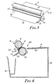
- the thermal lamination apparatus 12 shown in Figures 1 and 2 is shown as part of a larger apparatus 36.
- the larger apparatus 36 includes a frame 38 and a laminating assembly 40 supported by the frame 38.
- the laminating assembly 40 includes an assembly surface 42 across which the materials 10 can rest.
- the first laminating member 18 is positioned adjacent to the assembly surface 42.
- a first heating means (not shown) heats the first laminating member to a first temperature.
- a second laminating member 20 is positioned relative to the assembly surface 42 and the first laminating member 18 such that the materials 10 can be moved from the assembly surface 42 and passed between the first and second laminating members 18, 20 and such that heat and pressure are applied to the materials 10 when passing between the first and second laminating members 18, 20.
- a second heating means (not shown) can heat the second laminating member 20. As previously noted, the heat and pressure applied to the materials 10 form the laminate 26.
- a guiding assembly 44 is supported by the frame 38 and positioned relative to the laminating assembly 40 to guide the laminate 26 from the laminating assembly 40.
- the guiding assembly includes a first guide 22 positioned relative to the first and second laminating members 18, 20 to enable the first guide 22 to turn the laminate 26 exiting from between the first and second laminating members 18, 20 in a first direction away from the first laminating member 18 and cause the laminate 26 to have a curvature.
- a second guide 24 is positioned relative to the first guide 22 to turn the laminate 26 in a second direction. Turning the laminate from the first direction to the second direction causes the laminate 26 to have a reversed curvature.
- a trough 46 is positioned relative to the second guide 24 for receiving and holding the laminate 26 after being turned by the second guide 24.
Landscapes
- Lining Or Joining Of Plastics Or The Like (AREA)
- Registering, Tensioning, Guiding Webs, And Rollers Therefor (AREA)
- Laminated Bodies (AREA)
Claims (9)
- Vorrichtung zum thermischen Laminieren von Materialien (10), um ein Laminat zu bilden, und zum Führen des Laminats, die aufweist:ein erstes Laminierungsglied (18);eine erste Erwärmungseinrichtung zum Erwärmen des ersten Laminierungsgliedes auf eine erste Temperatur;ein zweites Laminierungsglied (20), das relativ zum ersten Laminierungsglied (18) angeordnet ist, um es zuzulassen, daß die Materialien durch eine Berührungsquetschstelle (28) zwischen den ersten und zweiten Laminierungsgliedern (18,20) hindurch gehen, so daß die Materialien (10) auf eine Laminierungstemperatur erwärmt werden, und so daß die ersten und zweiten Laminierungsglieder (18,20) Druck auf die Materialien (10) ausüben können, um das Laminat (26) zu bilden;eine erste Führung (22), die relativ zu den ersten und zweiten Laminierungsgliedern (18,20) angeordnet ist, um es zu ermöglichen, daß die erste Führung das Laminat (26) in eine erste Richtung weg vom ersten Laminierungsglied (18) dreht, wobei das Drehen des Laminats (26) in die erste Richtung bewirkt, daß das Laminat (26) eine Krümmung an einer Position aufweist, die dem Austritt des Laminats aus der Berührungsquetschstelle unmittelbar folgt; undeine zweite Führung (24), die relativ zur ersten Führung (22) angeordnet ist, um es zu ermöglichen, daß die zweite Führung (24) das Laminat (26) in eine zweite Richtung dreht, wobei das Drehen des Laminats (26) von der ersten Richtung in die zweite Richtung die Krümmung des Laminats (26) umkehrt.
- Vorrichtung nach Anspruch 1, die ferner eine zweite Erwärmungseinrichtung zum Erwärmen des zweiten Laminierungsgliedes auf eine zweite Temperatur aufweist, die tiefer als die erste Temperatur ist.
- Vorrichtung nach Anspruch 1 oder 2, wobei das erste Laminierungsglied (18) eine erste Walze ist, wobei das zweite Laminierungsglied (20) eine zweite Walze ist.
- Vorrichtung nach Anspruch 1, 2 oder 3, wobei der Druck, der auf die Materialien (10) ausgeübt wird, zwischen 2,10 und 2,52 Kilogramm pro Quadratzentimeter beträgt.
- Vorrichtung nach Anspruch 2, 3 oder 4, wobei die erste Temperatur zwischen 130 und 155 Grad Celsius beträgt und die zweite Temperatur zwischen 60 und 80 Grad Celsius beträgt.
- Vorrichtung nach einem der Ansprüche 1 bis 5, wobei die ersten und zweiten Führungen (22,24) angeordnet sind, um zu bewirken, daß das Laminat (26) einem allgemein S-förmigen Weg folgt, wenn das Laminat (26) zwischen den ersten und zweiten Laminierungsgliedern (18,20) austritt.
- Vorrichtung nach einem der Ansprüche 1 bis 6, wobei die zweite Führung (24) so angeordnet ist, daß die umgekehrte Krümmung einen Radius aufweist, der ausreichend klein ist, um ein Verziehen zu minimieren, jedoch ausreichend groß, um ein Dehnen des Laminats (26) zu minimieren.
- Vorrichtung nach einem der Ansprüche 1 bis 7, wobei die erste Führung (22) angeordnet ist, um das Laminat (26) am zweiten Laminierungsglied (20) zu führen, was bewirkt, daß das zweite Laminierungsglied (20) das Laminat (26) auf einer größeren Distanz berührt, als es das erste Laminierungsglied (18) tut.
- Vorrichtung nach einem der Ansprüche 1 bis 8, wobei die ersten und zweiten Führungen (22,24) das Laminat (26) berühren, bevor sich das Laminat (26) merklich unter die Laminierungstemperatur abkühlt.
Applications Claiming Priority (3)
| Application Number | Priority Date | Filing Date | Title |
|---|---|---|---|
| US08/405,531 US5641374A (en) | 1995-03-16 | 1995-03-16 | Apparatus and method for preventing defects during the lamination of materials |
| PCT/US1996/001552 WO1996028301A1 (en) | 1995-03-16 | 1996-02-06 | Apparatus and method for preventing defects during the lamination of materials |
| US405531 | 1999-09-24 |
Publications (2)
| Publication Number | Publication Date |
|---|---|
| EP0814958A1 EP0814958A1 (de) | 1998-01-07 |
| EP0814958B1 true EP0814958B1 (de) | 2000-08-09 |
Family
ID=23604090
Family Applications (1)
| Application Number | Title | Priority Date | Filing Date |
|---|---|---|---|
| EP96905376A Expired - Lifetime EP0814958B1 (de) | 1995-03-16 | 1996-02-06 | Vorrichtung zum verhindern von fehlern während der kaschierung von materialien |
Country Status (6)
| Country | Link |
|---|---|
| US (1) | US5641374A (de) |
| EP (1) | EP0814958B1 (de) |
| JP (1) | JPH11501878A (de) |
| AU (1) | AU4915396A (de) |
| DE (1) | DE69609705T2 (de) |
| WO (1) | WO1996028301A1 (de) |
Families Citing this family (8)
| Publication number | Priority date | Publication date | Assignee | Title |
|---|---|---|---|---|
| US5849388A (en) * | 1996-02-02 | 1998-12-15 | Imation Corp. | Article, apparatus and method for cooling a thermally processed material |
| US6221545B1 (en) | 1999-09-09 | 2001-04-24 | Imation Corp. | Adhesives for preparing a multilayer laminate featuring an ink-bearing surface bonded to a second surface |
| WO2007048145A2 (en) | 2005-10-21 | 2007-04-26 | Entrotech, Inc. | Protective sheets, articles, and methods |
| US10035932B2 (en) | 2007-09-25 | 2018-07-31 | Aero Advanced Paint Technology, Inc. | Paint replacement films, composites therefrom, and related methods |
| US10981371B2 (en) | 2008-01-19 | 2021-04-20 | Entrotech, Inc. | Protected graphics and related methods |
| JP6439347B2 (ja) * | 2014-09-25 | 2018-12-19 | セイコーエプソン株式会社 | シート製造装置 |
| SI3448949T1 (sl) | 2016-09-20 | 2024-02-29 | Ppg Advanced Surface Technologies, Llc | Aplikacije sloja laka z zmanjšanimi pomanjkljivostmi, artikli in postopki |
| JP6597983B2 (ja) * | 2017-10-23 | 2019-10-30 | パナソニックIpマネジメント株式会社 | ロールプレス装置 |
Family Cites Families (19)
| Publication number | Priority date | Publication date | Assignee | Title |
|---|---|---|---|---|
| US2700630A (en) * | 1952-09-18 | 1955-01-25 | Firestone Tire & Rubber Co | Vinyl leather products and process of producing same |
| US2771388A (en) * | 1953-06-18 | 1956-11-20 | Union Carbide & Carbon Corp | Method of laminating layers of thermoplastic foil |
| US2956917A (en) * | 1956-03-06 | 1960-10-18 | Du Pont | Article of manufacture and process of making same |
| US3458375A (en) * | 1965-04-14 | 1969-07-29 | Riegel Paper Corp | Noncurl lamination |
| US4069081A (en) * | 1976-08-04 | 1978-01-17 | Sealtran Corporation | Method for protective film lamination with curl control |
| DE3586510T2 (de) * | 1984-05-31 | 1993-01-28 | Fuji Photo Film Co Ltd | Verfahren und vorrichtung zur bilduebertragung. |
| EP0226376A3 (de) * | 1985-12-10 | 1988-09-21 | Aeci Limited | Handhabung thermoplastischer Bahnen während ihrer Heizung |
| JPS62216730A (ja) * | 1986-03-18 | 1987-09-24 | Gunze Ltd | 熱圧着ラミネ−ト方法及び装置 |
| GB2192582B (en) * | 1986-07-14 | 1990-03-14 | Somar Corp | Laminator |
| US4865675A (en) * | 1986-09-25 | 1989-09-12 | Canon Kabushiki Kaisha | Process of and apparatus for hot pressure adhesion treatments |
| JPS63196447A (ja) * | 1987-02-09 | 1988-08-15 | Matsushita Electric Ind Co Ltd | 記録装置 |
| US4909890A (en) * | 1988-05-06 | 1990-03-20 | Bonnyman Arthur W | Apparatus for protective film lamination |
| US4943222A (en) * | 1989-04-17 | 1990-07-24 | Shell Oil Company | Apparatus for forming preformed material |
| US4946640A (en) * | 1989-04-17 | 1990-08-07 | Shell Oil Company | Method for forming preformed material |
| JPH04168009A (ja) * | 1990-10-31 | 1992-06-16 | Dainippon Ink & Chem Inc | 積層板の製造方法 |
| JPH04173142A (ja) * | 1990-11-02 | 1992-06-19 | Mitsui Petrochem Ind Ltd | シート積層装置 |
| JPH04243765A (ja) * | 1991-01-23 | 1992-08-31 | Canon Inc | 排紙装置 |
| GB9126401D0 (en) * | 1991-12-12 | 1992-02-12 | Xerox Corp | Sheet curl control apparatus |
| US5316539A (en) * | 1992-09-01 | 1994-05-31 | Lexmark International, Inc. | Self-adjusting paper recurler |
-
1995
- 1995-03-16 US US08/405,531 patent/US5641374A/en not_active Expired - Fee Related
-
1996
- 1996-02-06 EP EP96905376A patent/EP0814958B1/de not_active Expired - Lifetime
- 1996-02-06 WO PCT/US1996/001552 patent/WO1996028301A1/en not_active Ceased
- 1996-02-06 JP JP8527580A patent/JPH11501878A/ja active Pending
- 1996-02-06 DE DE69609705T patent/DE69609705T2/de not_active Expired - Fee Related
- 1996-02-06 AU AU49153/96A patent/AU4915396A/en not_active Abandoned
Also Published As
| Publication number | Publication date |
|---|---|
| US5641374A (en) | 1997-06-24 |
| DE69609705T2 (de) | 2000-12-28 |
| JPH11501878A (ja) | 1999-02-16 |
| DE69609705D1 (de) | 2000-09-14 |
| EP0814958A1 (de) | 1998-01-07 |
| WO1996028301A1 (en) | 1996-09-19 |
| AU4915396A (en) | 1996-10-02 |
Similar Documents
| Publication | Publication Date | Title |
|---|---|---|
| AU649237B2 (en) | Method and apparatus for the manufacture of printed and embossed floor covering | |
| US5582669A (en) | Method for providing a protective overcoat on an image carrying medium utilizing a heated roller and a cooled roller | |
| US7785436B2 (en) | Laminating method for forming a laminate layer on a recording surface of a recording medium | |
| GB2295577A (en) | Delaminator apparatus | |
| US5641374A (en) | Apparatus and method for preventing defects during the lamination of materials | |
| US4259143A (en) | Laminating machine | |
| EP0329439A3 (de) | Glanzverfahren und -vorrichtung für Schichten | |
| US5927189A (en) | Method and apparatus for thermal fusing with two textured endless belts | |
| EP0778127B1 (de) | Verfahren zum Herstellen eines mehrschichtigen thermoplastischen Films, mehrschichtiger thermoplastischer Film und warmgeformter Artikel hergestellt aus diesem Film | |
| US5656127A (en) | Device for initiating the delamination of an image suited for dry processing | |
| JP2971846B2 (ja) | 長尺物のラッピング転写方法及びラッピング転写マシン | |
| JP3066389B2 (ja) | プリンタ用融着装置 | |
| US4892994A (en) | Curling prevention device of thermal developing machine | |
| US20030116263A1 (en) | Method and apparatus for applying a layer of lacquer to an upper side of a printed medium | |
| EP0814962B1 (de) | Verfahren und vorrichtung zum abziehen von laminatschichten, die ein bild tragendes medium enthalten | |
| JPH0348587Y2 (de) | ||
| US6802355B2 (en) | Overcoat application peel apparatus | |
| US5493363A (en) | Image recording apparatus and variable diameter conveying rollers with V-shaped pressure piece at exposure station | |
| EP1324881B1 (de) | Maschine zur warmlaminierung eines trockenfotoresistfilms auf eine platte für eine leiterplatte | |
| WO1999007802A1 (en) | Methods and apparatus for laminating sheet material | |
| US5711831A (en) | System and method for controlling label curl | |
| JPS63274968A (ja) | 定着方法 | |
| CN1178500A (zh) | 防止在材料层压过程中产生缺陷的装置和方法 | |
| US5573631A (en) | Manually-operable de-laminator apparatus | |
| JPS63101850A (ja) | 熱現像装置 |
Legal Events
| Date | Code | Title | Description |
|---|---|---|---|
| PUAI | Public reference made under article 153(3) epc to a published international application that has entered the european phase |
Free format text: ORIGINAL CODE: 0009012 |
|
| 17P | Request for examination filed |
Effective date: 19971015 |
|
| AK | Designated contracting states |
Kind code of ref document: A1 Designated state(s): DE FR GB IT |
|
| 17Q | First examination report despatched |
Effective date: 19990112 |
|
| RTI1 | Title (correction) |
Free format text: APPARATUS FOR PREVENTING DEFECTS DURING THE LAMINATION OF MATERIALS |
|
| GRAG | Despatch of communication of intention to grant |
Free format text: ORIGINAL CODE: EPIDOS AGRA |
|
| GRAG | Despatch of communication of intention to grant |
Free format text: ORIGINAL CODE: EPIDOS AGRA |
|
| GRAG | Despatch of communication of intention to grant |
Free format text: ORIGINAL CODE: EPIDOS AGRA |
|
| GRAH | Despatch of communication of intention to grant a patent |
Free format text: ORIGINAL CODE: EPIDOS IGRA |
|
| GRAH | Despatch of communication of intention to grant a patent |
Free format text: ORIGINAL CODE: EPIDOS IGRA |
|
| GRAA | (expected) grant |
Free format text: ORIGINAL CODE: 0009210 |
|
| AK | Designated contracting states |
Kind code of ref document: B1 Designated state(s): DE FR GB IT |
|
| PG25 | Lapsed in a contracting state [announced via postgrant information from national office to epo] |
Ref country code: IT Free format text: LAPSE BECAUSE OF FAILURE TO SUBMIT A TRANSLATION OF THE DESCRIPTION OR TO PAY THE FEE WITHIN THE PRE;WARNING: LAPSES OF ITALIAN PATENTS WITH EFFECTIVE DATE BEFORE 2007 MAY HAVE OCCURRED AT ANY TIME BEFORE 2007. THE CORRECT EFFECTIVE DATE MAY BE DIFFERENT FROM THE ONE RECORDED.SCRIBED TIME-LIMIT Effective date: 20000809 Ref country code: FR Free format text: LAPSE BECAUSE OF FAILURE TO SUBMIT A TRANSLATION OF THE DESCRIPTION OR TO PAY THE FEE WITHIN THE PRESCRIBED TIME-LIMIT Effective date: 20000809 |
|
| REF | Corresponds to: |
Ref document number: 69609705 Country of ref document: DE Date of ref document: 20000914 |
|
| EN | Fr: translation not filed | ||
| PGFP | Annual fee paid to national office [announced via postgrant information from national office to epo] |
Ref country code: GB Payment date: 20010118 Year of fee payment: 6 |
|
| PLBE | No opposition filed within time limit |
Free format text: ORIGINAL CODE: 0009261 |
|
| STAA | Information on the status of an ep patent application or granted ep patent |
Free format text: STATUS: NO OPPOSITION FILED WITHIN TIME LIMIT |
|
| 26N | No opposition filed | ||
| REG | Reference to a national code |
Ref country code: GB Ref legal event code: IF02 |
|
| PG25 | Lapsed in a contracting state [announced via postgrant information from national office to epo] |
Ref country code: GB Free format text: LAPSE BECAUSE OF NON-PAYMENT OF DUE FEES Effective date: 20020206 |
|
| GBPC | Gb: european patent ceased through non-payment of renewal fee |
Effective date: 20020206 |
|
| PGFP | Annual fee paid to national office [announced via postgrant information from national office to epo] |
Ref country code: DE Payment date: 20030228 Year of fee payment: 8 |
|
| PG25 | Lapsed in a contracting state [announced via postgrant information from national office to epo] |
Ref country code: DE Free format text: LAPSE BECAUSE OF NON-PAYMENT OF DUE FEES Effective date: 20040901 |