EP0815500B1 - Dispositif permettant de tenir compte du temps de reaction d'un equipement commande en fonction du trajet de deplacement - Google Patents
Dispositif permettant de tenir compte du temps de reaction d'un equipement commande en fonction du trajet de deplacement Download PDFInfo
- Publication number
- EP0815500B1 EP0815500B1 EP96907255A EP96907255A EP0815500B1 EP 0815500 B1 EP0815500 B1 EP 0815500B1 EP 96907255 A EP96907255 A EP 96907255A EP 96907255 A EP96907255 A EP 96907255A EP 0815500 B1 EP0815500 B1 EP 0815500B1
- Authority
- EP
- European Patent Office
- Prior art keywords
- travel
- equipment
- actual value
- item
- reaction time
- Prior art date
- Legal status (The legal status is an assumption and is not a legal conclusion. Google has not performed a legal analysis and makes no representation as to the accuracy of the status listed.)
- Expired - Lifetime
Links
Images

Classifications
-
- G—PHYSICS
- G05—CONTROLLING; REGULATING
- G05B—CONTROL OR REGULATING SYSTEMS IN GENERAL; FUNCTIONAL ELEMENTS OF SUCH SYSTEMS; MONITORING OR TESTING ARRANGEMENTS FOR SUCH SYSTEMS OR ELEMENTS
- G05B19/00—Program-control systems
- G05B19/02—Program-control systems electric
- G05B19/18—Numerical control [NC], i.e. automatically operating machines, in particular machine tools, e.g. in a manufacturing environment, so as to execute positioning, movement or co-ordinated operations by means of program data in numerical form
- G05B19/416—Numerical control [NC], i.e. automatically operating machines, in particular machine tools, e.g. in a manufacturing environment, so as to execute positioning, movement or co-ordinated operations by means of program data in numerical form characterised by control of velocity, acceleration or deceleration
-
- G—PHYSICS
- G05—CONTROLLING; REGULATING
- G05B—CONTROL OR REGULATING SYSTEMS IN GENERAL; FUNCTIONAL ELEMENTS OF SUCH SYSTEMS; MONITORING OR TESTING ARRANGEMENTS FOR SUCH SYSTEMS OR ELEMENTS
- G05B2219/00—Program-control systems
- G05B2219/30—Nc systems
- G05B2219/34—Director, elements to supervisory
- G05B2219/34387—Delay command as function of speed
-
- G—PHYSICS
- G05—CONTROLLING; REGULATING
- G05B—CONTROL OR REGULATING SYSTEMS IN GENERAL; FUNCTIONAL ELEMENTS OF SUCH SYSTEMS; MONITORING OR TESTING ARRANGEMENTS FOR SUCH SYSTEMS OR ELEMENTS
- G05B2219/00—Program-control systems
- G05B2219/30—Nc systems
- G05B2219/34—Director, elements to supervisory
- G05B2219/34388—Detect correct moment, position, advanced, delayed, then next command
-
- G—PHYSICS
- G05—CONTROLLING; REGULATING
- G05B—CONTROL OR REGULATING SYSTEMS IN GENERAL; FUNCTIONAL ELEMENTS OF SUCH SYSTEMS; MONITORING OR TESTING ARRANGEMENTS FOR SUCH SYSTEMS OR ELEMENTS
- G05B2219/00—Program-control systems
- G05B2219/30—Nc systems
- G05B2219/34—Director, elements to supervisory
- G05B2219/34391—Synchronize axis movement and tool action, delay action, simulation inertia
Definitions
- triggering travel path This is in particular a linear one or rotary travel of an element within the first resource, e.g. around a rotating shaft or one Sledge of the same.
- the current actual value of the triggering Travel path is recorded by a position encoder. So can when predetermined target values are reached along this travel path of the first resource e.g. Binary outputs of the Control can be activated or deactivated.
- switching points can e.g. the state of this Switched resources, or one or more other equipment is operated in the technical system, e.g.
- a programmable logic controller can have a large number of such travel setpoints together with assigned binary control commands for a triggering Travel path can be stored. A certain binary Control command is then executed when the actual value of the triggering Travel the size of an associated, stored Has reached the setpoint.
- Such an arrangement can also be referred to as an "electronic cam controller" become.
- EP 1 357 754 A2 describes an adjustment device the position of the rotating shaft of an electric motor is known.
- a braking process should be completed so that the Rotary shaft when a predetermined position setpoint is reached at Standstill comes.
- those required for braking Response time occurs, the current shaft position, as well as their speed and acceleration. Because the resources that trigger and control the process identical in the way of a sequential process are compensated by simply measuring the Adjustment path without division.
- the invention is based, taking into account the task the response time of a device that can be switched over in the state a technical system when activated at the moment of reaching so-called milestones one that can be run at variable speeds Travel of another piece of equipment by means of a controller Can be achieved with little effort, in particular without discrete division.
- the duration of the measuring cycle for Acquisition of the current value of the travel speed along the triggering travel path of an item of equipment technical system corresponding size is not constant. Much more the duration of the measurement corresponds exactly to the reaction time of the same or another technical equipment System which, when predetermined setpoints are reached of the triggering travel path can be activated or deactivated should, i.e. generally switched its operating state shall be.
- the Current actual value of the triggering travel path of the first item of equipment recorded and saved as a "start actual value”. After the stored response time of the to be controlled Equipment, i.e. at the end of the measuring cycle again the current actual value of the trigger Travel path of the corresponding equipment recorded and saved as a "final actual value".
- the determination according to the invention of the speed-dependent is advantageous Vorhaltweges cyclically triggered, see above that the stored setpoints serving as switching points always the current travel speed on the triggering Travel of the first item of equipment shifted accordingly can be.
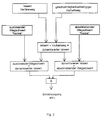
- FIG. 1 is an example in the form of a time diagram the detection of the speed-dependent lead travel VW shown according to the invention.
- This is a measurement cycle triggered by the falling edge of a start pulse S.
- the current value IS of the triggering travel path is recorded and saved.
- the measurement is made at the end of the measuring cycle, which according to the invention one with the response time of the to be controlled Equipment has a corresponding measuring duration TM, i.e. repeated at time T2.
Landscapes
- Engineering & Computer Science (AREA)
- Human Computer Interaction (AREA)
- Manufacturing & Machinery (AREA)
- Physics & Mathematics (AREA)
- General Physics & Mathematics (AREA)
- Automation & Control Theory (AREA)
- Feedback Control In General (AREA)
- Control Of Transmission Device (AREA)
- Surgical Instruments (AREA)
- Electrical Discharge Machining, Electrochemical Machining, And Combined Machining (AREA)
- Management, Administration, Business Operations System, And Electronic Commerce (AREA)
- Portable Nailing Machines And Staplers (AREA)
- Time Recorders, Dirve Recorders, Access Control (AREA)
- Holders For Apparel And Elements Relating To Apparel (AREA)
- Automatic Disk Changers (AREA)
- Traffic Control Systems (AREA)
- Control Of Position, Course, Altitude, Or Attitude Of Moving Bodies (AREA)
Claims (2)
- Dispositif de compensation de la durée de réaction d'un moyen de fonctionnement à commander d'une installation technique, moyen qui lorsqu'est atteinte une valeur de consigne de trajet sur un trajet de déplacement d'un moyen de fonctionnement déclenchant parcouru à une vitesse instantanée, doit être activé, désactivé ou mis à l'état de fonctionnement,
caractérisé para) un indicateur de position servant à détecter la valeur réelle du trajet de déplacement du moyen de fonctionnement déclenchant,b) des moyens de mémorisation de la durée de réaction du moyen de fonctionnement à commander,c) des moyens de mémorisation d'une première valeur réelle en tant que valeur (T1) réelle initiale du trajet de déplacement du moyen de fonctionnement déclenchant,d) des moyens de mémorisation d'une deuxième valeur réelle en tant que valeur (T2) réelle finale du trajet de déplacement du moyen de fonctionnement déclenchant après expiration d'un laps de temps correspondant à la durée de réaction du moyen de fonctionnement à commander,e) des moyens de détermination d'une valeur instantanée d'un trajet (VW) d'anticipation par soustraction de la première valeur réelle de la deuxième valeur réelle etf) des moyens de réduction de la valeur de consigne de trajet, en tant qu'une valeur de consigne de trajet corrigée du moyen de fonctionnement déclenchant, de la valeur instantanée du trajet (VW) d'anticipation. - Dispositif de compensation de la durée de réaction d'un moyen de fonctionnement à commander d'une installation technique, moyen qui lorsqu'est atteinte une valeur de consigne de trajet sur un trajet de déplacement d'un moyen de fonctionnement déclenchant parcouru à une vitesse instantanée, doit être activé, désactivé ou mis à l'état de fonctionnement,
caractérisé para) un indicateur de position servant à détecter la valeur réelle du trajet de déplacement du moyen de fonctionnement déclenchant,b) des moyens de mémorisation de la durée de réaction du moyen de fonctionnement à commander,c) des moyens de mémorisation d'une première valeur réelle en tant que valeur (T1) réelle initiale du trajet de déplacement du moyen de fonctionnement déclenchant,d) des moyens de mémorisation d'une deuxième valeur réelle en tant que valeur (T2) réelle finale du trajet de déplacement du moyen de fonctionnement déclenchant après expiration d'un laps de temps correspondant à la durée de réaction du moyen de fonctionnement à commander,e) des moyens de détermination d'une valeur instantanée d'un trajet (VW) d'anticipation par soustraction de la première valeur réelle de la deuxième valeur réelle etf) des moyens pour augmenter la valeur réelle du trajet de déplacement, en tant que valeur réelle dynamisée du moyen de fonctionnement, déclenchant, de la valeur instantanée du trajet (VW) d'anticipation.
Applications Claiming Priority (3)
| Application Number | Priority Date | Filing Date | Title |
|---|---|---|---|
| DE29505468U | 1995-03-24 | ||
| DE29505468U DE29505468U1 (de) | 1995-03-29 | 1995-03-29 | Vorrichtung zur Berücksichtigung der Reaktionszeit eines Betriebsmittels bei einer von einem Verfahrweg abhängigen Ansteuerung desselben |
| PCT/DE1996/000494 WO1996030814A1 (fr) | 1995-03-24 | 1996-03-22 | Dispositif permettant de tenir compte du temps de reaction d'un equipement commande en fonction du trajet de deplacement |
Publications (2)
| Publication Number | Publication Date |
|---|---|
| EP0815500A1 EP0815500A1 (fr) | 1998-01-07 |
| EP0815500B1 true EP0815500B1 (fr) | 2000-12-20 |
Family
ID=8006165
Family Applications (1)
| Application Number | Title | Priority Date | Filing Date |
|---|---|---|---|
| EP96907255A Expired - Lifetime EP0815500B1 (fr) | 1995-03-24 | 1996-03-22 | Dispositif permettant de tenir compte du temps de reaction d'un equipement commande en fonction du trajet de deplacement |
Country Status (7)
| Country | Link |
|---|---|
| US (1) | US5935178A (fr) |
| EP (1) | EP0815500B1 (fr) |
| AT (1) | ATE198236T1 (fr) |
| DE (2) | DE29505468U1 (fr) |
| ES (1) | ES2153567T3 (fr) |
| TW (1) | TW493114B (fr) |
| WO (1) | WO1996030814A1 (fr) |
Cited By (2)
| Publication number | Priority date | Publication date | Assignee | Title |
|---|---|---|---|---|
| DE102010021640A1 (de) * | 2010-05-26 | 2011-12-01 | Robert Bosch Gmbh | Verfahren und Vorrichtung zur Ansteuerung einer Armatur |
| DE102022003510B3 (de) | 2022-09-23 | 2023-12-14 | INPRO Innovationsgesellschaft für fortgeschrittene Produktionssysteme in der Fahrzeugindustrie mbH | Vorrichtung und Verfahren zur Ermittlung von Defekten und/oder Mikrostörungen mindestens einer Antriebskomponente einer endlagengesteuerten Anlage |
Families Citing this family (2)
| Publication number | Priority date | Publication date | Assignee | Title |
|---|---|---|---|---|
| DE19743180A1 (de) * | 1997-09-30 | 1999-04-01 | Wabco Gmbh | Verfahren zum Schalten eines halbautomatischen KFZ-Getriebes |
| DE102004047971B4 (de) * | 2004-10-01 | 2013-07-04 | Alfing Kessler Sondermaschinen Gmbh | Vorrichtung und Verfahren zur Steuerung von Bewegungsabläufen bei Maschinen |
Family Cites Families (13)
| Publication number | Priority date | Publication date | Assignee | Title |
|---|---|---|---|---|
| US3555254A (en) * | 1967-04-17 | 1971-01-12 | Gerber Scientific Instr Co | Error correcting system and method for use with plotters, machine tools and the like |
| US3737751A (en) * | 1971-06-24 | 1973-06-05 | Ibm | Servomechanism stop control |
| US3888338A (en) * | 1973-10-03 | 1975-06-10 | Mcneil Corp | Electronic indexing system |
| GB2037456A (en) * | 1978-11-04 | 1980-07-09 | Fisons Ltd | Automatic control |
| JPS5776608A (en) * | 1980-10-30 | 1982-05-13 | Fanuc Ltd | Position error correction device |
| JPS5860310A (ja) * | 1981-10-05 | 1983-04-09 | Sankyo Seiki Mfg Co Ltd | 車載機器の制御装置 |
| DE3302063C2 (de) * | 1983-01-22 | 1986-06-19 | Brüstle, Michael, Dr.-Ing., 7000 Stuttgart | Einrichtung zur Kompensation von Lagefehlern an Werkzeug- oder Meßmaschinen sowie an Industrie-Robotern |
| JP2572564B2 (ja) * | 1983-08-22 | 1997-01-16 | 株式会社 エスジー | 電気モータの位置決め制御装置 |
| DE4012577C1 (fr) * | 1990-04-20 | 1991-04-18 | Robert Bosch Gmbh, 7000 Stuttgart, De | |
| EP0455938B1 (fr) * | 1990-05-11 | 1994-11-30 | Landis & Gyr Technology Innovation AG | Régulateur tout-ou-rien adaptatif |
| DE4226383C2 (de) * | 1992-08-10 | 1999-05-20 | Stuhl Regelsysteme Gmbh | Meß- und Regelverfahren für ein elektronisches Zwei-Punkt- oder Proportional-Regelgerät |
| JP3386548B2 (ja) * | 1994-01-31 | 2003-03-17 | トヨタ自動車株式会社 | フィードバック式加工条件補正装置 |
| JPH08132332A (ja) * | 1994-11-04 | 1996-05-28 | Fanuc Ltd | 工作機械における位置ずれ補正方法 |
-
1995
- 1995-03-29 DE DE29505468U patent/DE29505468U1/de not_active Expired - Lifetime
-
1996
- 1996-03-22 AT AT96907255T patent/ATE198236T1/de not_active IP Right Cessation
- 1996-03-22 DE DE59606234T patent/DE59606234D1/de not_active Expired - Lifetime
- 1996-03-22 WO PCT/DE1996/000494 patent/WO1996030814A1/fr not_active Ceased
- 1996-03-22 US US08/930,465 patent/US5935178A/en not_active Expired - Lifetime
- 1996-03-22 EP EP96907255A patent/EP0815500B1/fr not_active Expired - Lifetime
- 1996-03-22 ES ES96907255T patent/ES2153567T3/es not_active Expired - Lifetime
- 1996-04-06 TW TW085104022A patent/TW493114B/zh active
Cited By (3)
| Publication number | Priority date | Publication date | Assignee | Title |
|---|---|---|---|---|
| DE102010021640A1 (de) * | 2010-05-26 | 2011-12-01 | Robert Bosch Gmbh | Verfahren und Vorrichtung zur Ansteuerung einer Armatur |
| DE102010021640B4 (de) * | 2010-05-26 | 2024-09-12 | Aventics Gmbh | Verfahren und Vorrichtung zur Ansteuerung einer Armatur |
| DE102022003510B3 (de) | 2022-09-23 | 2023-12-14 | INPRO Innovationsgesellschaft für fortgeschrittene Produktionssysteme in der Fahrzeugindustrie mbH | Vorrichtung und Verfahren zur Ermittlung von Defekten und/oder Mikrostörungen mindestens einer Antriebskomponente einer endlagengesteuerten Anlage |
Also Published As
| Publication number | Publication date |
|---|---|
| US5935178A (en) | 1999-08-10 |
| TW493114B (en) | 2002-07-01 |
| DE59606234D1 (de) | 2001-01-25 |
| ES2153567T3 (es) | 2001-03-01 |
| WO1996030814A1 (fr) | 1996-10-03 |
| DE29505468U1 (de) | 1995-06-01 |
| ATE198236T1 (de) | 2001-01-15 |
| EP0815500A1 (fr) | 1998-01-07 |
Similar Documents
| Publication | Publication Date | Title |
|---|---|---|
| EP0744676B1 (fr) | Méthode et dispositif de sûreté de fonctionnement d'une commande numérique pour une machine-outil ou un robot | |
| DE69921098T2 (de) | Kompensation der bewegungsunstetigkeit bei betriebsmodusumschaltung einer nachgeführten achse | |
| DE3009405C2 (de) | Verfahren und Anordnung zum Steuern von Füllelementen in Füllmaschinen | |
| DE2633846C2 (de) | Numerische Regeleinrichtung | |
| DE2111635C2 (de) | Einrichtung zum Umsetzen der sich im Vergleich zu einer Bezugsphasenlage ändernden Phasenlage eines periodischen Eingangssignals in eine Folge von Impulsen | |
| EP3438773A1 (fr) | Usinage de pièces à compensation d'erreur basées sur modèles | |
| DE2332664C2 (de) | Programmsteuerungssystem | |
| DE2334455B2 (de) | Schaltungsanordnung zum Abbremsen eines numerisch gesteuerten Antriebssystems | |
| DE1588329B2 (de) | Einrichtung zur digitalen drehzahlregelung eines gleichstrommotors | |
| DE2729372C3 (de) | Anordnung zur Überwachung einer rechnergeführten numerisch gesteuerten Werkzeugmaschine | |
| DE3815530C2 (fr) | ||
| DE29505468U1 (de) | Vorrichtung zur Berücksichtigung der Reaktionszeit eines Betriebsmittels bei einer von einem Verfahrweg abhängigen Ansteuerung desselben | |
| DE102017221562A1 (de) | Steuereinrichtung für einen Servomotor, Verfahren zum Steuern eines Servomotors und Computerprogramm | |
| DE1538607A1 (de) | Numerische Werkzeugmaschinen-Steuerung | |
| DE68916917T2 (de) | Verfahren zur rückkehr zum ursprung. | |
| DE3103701C2 (fr) | ||
| DE2627209B2 (de) | Gerät zur Registrierung der zurückgelegten Lastzyklen von umlaufenden Maschinen | |
| DE3709129A1 (de) | Numerische steuervorrichtung | |
| DD226236A1 (de) | Freiprogrammierbares steuerungssystem fuer werkzeugmaschinenkomplexe, beispielsweise fuer pressenkomplexe | |
| DE2139053A1 (de) | Numerische Werkzeugmaschinensteue rung | |
| DE4327324B4 (de) | Verfahren zur Bestimmung eines Prozeßereignisses | |
| DE3431841C2 (fr) | ||
| DE3011148A1 (de) | Vorrichtung zum positionieren eines verstellbaren maschinenteils, insbesondere einer werkzeugmaschine | |
| DE2511640A1 (de) | Verfahren zur steuerung der geschwindigkeit eines motors und vorrichtung zur durchfuehrung des verfahrens | |
| DE1438241C (de) | Überwachungsvorrichtung für eine periodisch betriebene Maschine |
Legal Events
| Date | Code | Title | Description |
|---|---|---|---|
| PUAI | Public reference made under article 153(3) epc to a published international application that has entered the european phase |
Free format text: ORIGINAL CODE: 0009012 |
|
| 17P | Request for examination filed |
Effective date: 19970918 |
|
| AK | Designated contracting states |
Kind code of ref document: A1 Designated state(s): AT CH DE ES FR GB LI |
|
| GRAG | Despatch of communication of intention to grant |
Free format text: ORIGINAL CODE: EPIDOS AGRA |
|
| GRAG | Despatch of communication of intention to grant |
Free format text: ORIGINAL CODE: EPIDOS AGRA |
|
| GRAH | Despatch of communication of intention to grant a patent |
Free format text: ORIGINAL CODE: EPIDOS IGRA |
|
| 17Q | First examination report despatched |
Effective date: 20000516 |
|
| GRAH | Despatch of communication of intention to grant a patent |
Free format text: ORIGINAL CODE: EPIDOS IGRA |
|
| GRAA | (expected) grant |
Free format text: ORIGINAL CODE: 0009210 |
|
| AK | Designated contracting states |
Kind code of ref document: B1 Designated state(s): AT CH DE ES FR GB LI |
|
| REF | Corresponds to: |
Ref document number: 198236 Country of ref document: AT Date of ref document: 20010115 Kind code of ref document: T |
|
| REG | Reference to a national code |
Ref country code: CH Ref legal event code: NV Representative=s name: SIEMENS SCHWEIZ AG Ref country code: CH Ref legal event code: EP |
|
| REF | Corresponds to: |
Ref document number: 59606234 Country of ref document: DE Date of ref document: 20010125 |
|
| ET | Fr: translation filed | ||
| REG | Reference to a national code |
Ref country code: ES Ref legal event code: FG2A Ref document number: 2153567 Country of ref document: ES Kind code of ref document: T3 |
|
| GBT | Gb: translation of ep patent filed (gb section 77(6)(a)/1977) |
Effective date: 20010228 |
|
| PLBE | No opposition filed within time limit |
Free format text: ORIGINAL CODE: 0009261 |
|
| STAA | Information on the status of an ep patent application or granted ep patent |
Free format text: STATUS: NO OPPOSITION FILED WITHIN TIME LIMIT |
|
| 26N | No opposition filed | ||
| REG | Reference to a national code |
Ref country code: GB Ref legal event code: IF02 |
|
| PGFP | Annual fee paid to national office [announced via postgrant information from national office to epo] |
Ref country code: ES Payment date: 20080416 Year of fee payment: 13 Ref country code: CH Payment date: 20080612 Year of fee payment: 13 |
|
| REG | Reference to a national code |
Ref country code: CH Ref legal event code: PCAR Free format text: SIEMENS SCHWEIZ AG;INTELLECTUAL PROPERTY FREILAGERSTRASSE 40;8047 ZUERICH (CH) |
|
| PGFP | Annual fee paid to national office [announced via postgrant information from national office to epo] |
Ref country code: AT Payment date: 20090213 Year of fee payment: 14 |
|
| REG | Reference to a national code |
Ref country code: CH Ref legal event code: PL |
|
| PG25 | Lapsed in a contracting state [announced via postgrant information from national office to epo] |
Ref country code: LI Free format text: LAPSE BECAUSE OF NON-PAYMENT OF DUE FEES Effective date: 20090331 Ref country code: CH Free format text: LAPSE BECAUSE OF NON-PAYMENT OF DUE FEES Effective date: 20090331 |
|
| REG | Reference to a national code |
Ref country code: ES Ref legal event code: FD2A Effective date: 20090323 |
|
| PG25 | Lapsed in a contracting state [announced via postgrant information from national office to epo] |
Ref country code: ES Free format text: LAPSE BECAUSE OF NON-PAYMENT OF DUE FEES Effective date: 20090323 |
|
| PG25 | Lapsed in a contracting state [announced via postgrant information from national office to epo] |
Ref country code: AT Free format text: LAPSE BECAUSE OF NON-PAYMENT OF DUE FEES Effective date: 20100322 |
|
| PG25 | Lapsed in a contracting state [announced via postgrant information from national office to epo] |
Ref country code: DE Free format text: LAPSE BECAUSE OF NON-PAYMENT OF DUE FEES Effective date: 20111001 |
|
| PGFP | Annual fee paid to national office [announced via postgrant information from national office to epo] |
Ref country code: DE Payment date: 20130521 Year of fee payment: 18 |
|
| PGFP | Annual fee paid to national office [announced via postgrant information from national office to epo] |
Ref country code: FR Payment date: 20140317 Year of fee payment: 19 |
|
| PGFP | Annual fee paid to national office [announced via postgrant information from national office to epo] |
Ref country code: GB Payment date: 20140312 Year of fee payment: 19 |
|
| REG | Reference to a national code |
Ref country code: DE Ref legal event code: R119 Ref document number: 59606234 Country of ref document: DE |
|
| REG | Reference to a national code |
Ref country code: DE Ref legal event code: R119 Ref document number: 59606234 Country of ref document: DE Effective date: 20141001 |
|
| GBPC | Gb: european patent ceased through non-payment of renewal fee |
Effective date: 20150322 |
|
| REG | Reference to a national code |
Ref country code: FR Ref legal event code: ST Effective date: 20151130 |
|
| PG25 | Lapsed in a contracting state [announced via postgrant information from national office to epo] |
Ref country code: GB Free format text: LAPSE BECAUSE OF NON-PAYMENT OF DUE FEES Effective date: 20150322 |
|
| PG25 | Lapsed in a contracting state [announced via postgrant information from national office to epo] |
Ref country code: FR Free format text: LAPSE BECAUSE OF NON-PAYMENT OF DUE FEES Effective date: 20150331 |
|
| PG25 | Lapsed in a contracting state [announced via postgrant information from national office to epo] |
Ref country code: DE Free format text: LAPSE BECAUSE OF NON-PAYMENT OF DUE FEES Effective date: 20141001 |