EP0815923A2 - Verfahren zur Oxidationskontrolle in Abgasentschwefelung - Google Patents
Verfahren zur Oxidationskontrolle in Abgasentschwefelung Download PDFInfo
- Publication number
- EP0815923A2 EP0815923A2 EP97610025A EP97610025A EP0815923A2 EP 0815923 A2 EP0815923 A2 EP 0815923A2 EP 97610025 A EP97610025 A EP 97610025A EP 97610025 A EP97610025 A EP 97610025A EP 0815923 A2 EP0815923 A2 EP 0815923A2
- Authority
- EP
- European Patent Office
- Prior art keywords
- oxidation
- absorbent liquid
- flue gas
- flow rate
- concentration
- Prior art date
- Legal status (The legal status is an assumption and is not a legal conclusion. Google has not performed a legal analysis and makes no representation as to the accuracy of the status listed.)
- Granted
Links
Images


Classifications
-
- B—PERFORMING OPERATIONS; TRANSPORTING
- B01—PHYSICAL OR CHEMICAL PROCESSES OR APPARATUS IN GENERAL
- B01D—SEPARATION
- B01D53/00—Separation of gases or vapours; Recovering vapours of volatile solvents from gases; Chemical or biological purification of waste gases, e.g. engine exhaust gases, smoke, fumes, flue gases, aerosols
- B01D53/34—Chemical or biological purification of waste gases
- B01D53/46—Removing components of defined structure
- B01D53/48—Sulfur compounds
- B01D53/50—Sulfur oxides
- B01D53/501—Sulfur oxides by treating the gases with a solution or a suspension of an alkali or earth-alkali or ammonium compound
-
- B—PERFORMING OPERATIONS; TRANSPORTING
- B01—PHYSICAL OR CHEMICAL PROCESSES OR APPARATUS IN GENERAL
- B01D—SEPARATION
- B01D53/00—Separation of gases or vapours; Recovering vapours of volatile solvents from gases; Chemical or biological purification of waste gases, e.g. engine exhaust gases, smoke, fumes, flue gases, aerosols
- B01D53/34—Chemical or biological purification of waste gases
- B01D53/346—Controlling the process
-
- Y—GENERAL TAGGING OF NEW TECHNOLOGICAL DEVELOPMENTS; GENERAL TAGGING OF CROSS-SECTIONAL TECHNOLOGIES SPANNING OVER SEVERAL SECTIONS OF THE IPC; TECHNICAL SUBJECTS COVERED BY FORMER USPC CROSS-REFERENCE ART COLLECTIONS [XRACs] AND DIGESTS
- Y10—TECHNICAL SUBJECTS COVERED BY FORMER USPC
- Y10S—TECHNICAL SUBJECTS COVERED BY FORMER USPC CROSS-REFERENCE ART COLLECTIONS [XRACs] AND DIGESTS
- Y10S423/00—Chemistry of inorganic compounds
- Y10S423/05—Automatic, including computer, control
Definitions
- the present invention relates to the art of wet flue gas desulfurization, utilizing a calcium compound such as limestone as an absorbent, and more particularly to a method for controlling the oxidation of sulfurous acid in an absorbing liquid.
- the state of the art utilizes a so-called in-situ process which does not require an oxidation tower and which operates by blowing air into a tank positioned at the bottom of an absorption tower in order to oxidize an absorbent slurry (an absorbing liquid in a form of a suspension of an absorbent comprising limestone) that has absorbed sulfurous acid to thereby produce gypsum as a by-product.
- an absorbent slurry an absorbing liquid in a form of a suspension of an absorbent comprising limestone
- the main reactions that take place during the treatment are indicated by the following reactions (1) through (3).
- JP-A Japanese Patent Provisional Publication (JP-A) No.60-226,403 discloses a process comprising continuous detection of a sulfite concentration (including the sulfurous acid present as an ion) in an absorbing liquid, and regulation of the oxidizing catalyst supply in accordance with a signal of deviation of the detected value from a preset value of the sulfite concentration.
- the sulfite concentration is determined by a procedure comprising taking a sample liquid by means of a measuring pump, generating a gas from the sample liquid by adding thereto an acid such as hydrochloric acid, and calculating the sulfite concentration of the sample liquid based on the concentration of sulfur dioxide in the generated gas of the preceding step.
- JP-B Japanese Patent Publication (JP-B) No.3-59,731 discloses a process comprising the steps of continuously detecting an oxidation-reduction potential (ORP) of an absorbent slurry and effecting a feed back control so that the detected value equals a desired sulfite concentration to thereby keep calcium sulfite completely oxidized (i.e., within a low concentration range close to zero).
- ORP oxidation-reduction potential
- JP-A Japanese Patent Provisional Publication
- JP-A Japanese Patent Provisional Publication
- JP-A Japanese Patent Provisional Publication
- this process is feasible in the case where the operational conditions including the quantity of sulfur dioxide [(flow rate of flue gas) x (concentration of sulfur dioxide)] in the flue gas gradually change.
- operational conditions including the quantity of sulfur dioxide [(flow rate of flue gas) x (concentration of sulfur dioxide)] in the flue gas gradually change.
- a problem arises in the case where operational conditions abruptly change. For example, a load change of a boiler, which is a source of flue gas, is generally abrupt. Therefore, this process can hardly follow the fluctuation in an operational condition that accompanies the above-mentioned load change, thus has not been practicable.
- the object of the present invention is to provide a method for controlling the oxidation in flue gas desulfurization which is capable of better meeting the change in the operational condition to realize a minute control of oxidation, and which is capable of maintaining the concentration of sulfurous acid in an absorbent liquid within a proper range in a highly reliable and efficient manner, even if an operational condition abruptly changes.
- the method for controlling the oxidation in flue gas desulfurization according to the present invention has the following constitution.
- the present invention provides a method for controlling oxidation in flue gas desulfurization whereby the following effects will result.
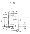
- Fig. 1 illustrates an example of the construction of a desulfurization apparatus for carrying out the method for controlling oxidation relating to the first embodiment of the present invention.
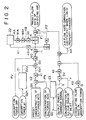
- Fig. 2 illustrates an example of the logic sequence of a specific treatment according to the method for controlling oxidation relating to the first embodiment of the present invention.
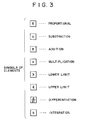
- Fig. 3 explains the symbols for elements in the above-mentioned logic sequence.
- Fig. 4 illustrates an example of the relationship between the concentration of sulfurous acid and oxidation-reduction potential of an absorbent liquid in the above-mentioned desulfurization apparatus.
- Fig. 5 explains the characteristics of proportional sensitivity in the above-mentioned logic sequence.
- Fig. 6 explains an upper limit of ORP deviation in the above-mentioned logic sequence.
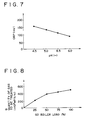
- Fig. 7 illustrates an example of the correlation between pH and ORP (the concentration of sulfurous acid being constant) of the absorbent liquid in the above-mentioned desulfurization apparatus.
- Fig. 8 illustrates an example of the correlation between boiler loads and flow rates of the (flue gas) gas to be treated in a thermal power plant equipped with the above-mentioned desulfurization apparatus.
- Fig. 9 illustrates an example of the correlation between the number of absorbent liquid circulating pumps (circulating flow rate) and the required quantity of oxidizing air in the above-mentioned desulfurization apparatus.
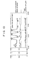
- Fig. 10 illustrates the results of a load fluctuation test (Example) to verify the effect of the method for controlling oxidation relating to the first embodiment of the present invention.
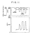
- Fig. 11 illustrates the results of a load fluctuation test (Comparative Example) to verify the effect of the method for controlling oxidation relating to the first embodiment of the present invention.
- Fig. 1 illustrates the construction of an apparatus for effecting the method for controlling oxidation in flue gas desulfurization which relates to the first embodiment of the present invention.
- a flue gas containing sulfur dioxide (SO 2 ) is introduced into an absorption tower 2 through a duct 1 and the flue gas, after desulfurization is discharged into the air through a duct 3.
- SO 2 sulfur dioxide
- An absorbent liquid that has passed through a line 4 is sprayed inside the absorption tower 2 to cause a gas/liquid contact between the absorbent slurry flowing down through a packed material 2a and a flue gas so that at least the sulfur dioxide in the flue gas is absorbed according to the aforementioned reaction (1).
- the absorbent slurry that has absorbed sulfur dioxide contacts with air (oxygen containing gas) which is blown in the form of minute bubbles from disperser nozzles 7 through a line 6 so that an oxidation of the aforementioned equation (2) and neutralization of the aforementioned equation (3) proceed in sequence to form gypsum (CaCO 4 ⁇ 2H 2 O).
- the oxidation, of equation (2) takes place also by an auto-oxidation due to air present in the flue gas.
- the ORP of the absorbent slurry is detected by an electrode 8 positioned in a tank 5.
- a commonly used platinum electrode is applicable as the electrode 8.
- the ORP detected by the electrode 8 is transmitted to a controller 10, which is based, for example, on an analogue computing circuit, via a signal line 9. According to the control explained below, the controller 10 determines a preset flow rate of oxidizing air, and transmits an opening or closing signal to a control valve 12 for opening regulation thereof through a signal line 11.
- Fresh limestone slurry is introduced through a line 13 into the tank 5, and a concentration of sulfurous acid in the slurry inside the tank 5 is constantly maintained at a low range by the air flow rate for forcible oxidation controlled by the controller 10, as explained below. Consequently, the slurry contains a slight amount of unreacted limestone together with a large amount of solid gypsum. Then, the slurry is withdrawn from a line 15, on the way to the line 4 by means of a circulating pump 14, to undergo a solid-liquid separation so as to obtain gypsum.
- the construction of the absorption tower 2 is not limited to a packed tower of Fig. 1, therefore other constructions including a spray-type and a liquid column-type may be used.
- an electrode for the detection of ORP is not limited to the inside of the tank 5, thus it may be, for example, on the line 4 or on a circulating line by means of an additional sampling pump.
- Fig. 3 illustrates the meanings of the symbols in the logic sequence of Fig. 2.
- the controller 10 receives the following inputs: PV as a detected ORP value from the electrode 8, DpH as a detected pH value of the absorbent slurry, PN as a detected value of the concentration of sulfurous acid of the absorbent slurry, GO as an output power command signal from a thermal power generating facility which is the source of flue gas, Y as a detected concentration of sulfur dioxide at the inlet of the absorption tower 2 and Q as a circulating flow rate of the absorbent slurry in the absorption tower 2.
- the value of F1 which constitutes a preset flow rate of oxidizing air F, is a control input determined by the ORP feed back control, as explained below.
- the value of F2 is a control input determined by the feed forward control as explained below.
- a target initial SV0 value of ORP is fed from the controller 10 based on a table 21 of optimum preset ORP against pH.
- the table 21 of optimum preset ORP against pH provides various target SV values of ORP corresponding to characteristics change of ORP against pH and includes predetermined characteristics, for example, of Fig. 7 That is, if the concentration of sulfurous acid is constant (for example, 2mmol/liter), an experiment provides the characteristics as shown in Fig. 7, which enables the determination of a target initial SV0 value of ORP based on the input of a pH value.
- a central value within the aforementioned proper range of the concentration of sulfurous acid (e.g., about 0.5 - 3mmol/liter) is preferably adopted as a preset concentration of sulfurous acid SN.
- the corrected target value SV1 is intended for a direct correction of the target control value SV of ORP based on the detected value of the concentration of sulfurous acid PN in order to avoid the situation where the concentration of sulfurous acid is constantly out of a preferred range, because of an abnormal change or the like of the property of the absorbent slurry causes an actual correlation between ORP and the concentration of sulfurous acid to deviate from the characteristics of the optimum preset ORP against pH shown in the table 21, despite the fact that ORP itself is normally controlled at or in the neighborhood of a target value.
- the value and polarity of the proportional factor k1 are set so that the corrected target value SV1 becomes a positive value proportional to the variation ⁇ 2 to such an extent that the target value SV of ORP is incremented to offset the variation ⁇ 2.
- the lower limit L does not allow the deviation ⁇ to lower further so as to avoid excessive change of the preset flow rate of oxidizing air (i.e., control input), as shown in Fig.6. It is set to be about -150mV of ORP as an example.
- control input F1 for the feed back control of the flow rate of oxidizing air is fed from the above-described final deviation ⁇ after so-called PID computation according to the following equation (4) based on the proportional element, integration element and differentiation element shown in Fig. 2.
- a proportional gain (proportional sensitivity) K of the equation (4) is calculated on a deviation ⁇ 1 which is obtained by reversing the polarity of the aforementioned deviation ⁇ . That is, firstly, the computation according to the following equation (5) is conducted using a proportional sensitivity optimizing computational element 22 to obtain a computational intermediate sensitivity KA.
- the proportional sensitivity optimizing computational element 22 increases the proportional sensitivity K in the region where a detected value PV of ORP is smaller than a preset value SV, in correspondence, for example, with a characteristics change of ORP against concentration of sulfurous acid shown in Fig. 4.
- a characteristic curve of ORP against concentration of sulfurous acid is known to exhibit an exponentially attenuated slope on a insufficient oxidizing side (on a side where the concentration of sulfurous acid increases) as shown in Fig. 4.
- Constants m, a and b in the equation (5) may be set to an appropriate value, respectively, to match the actual change of ORP in order to achieve the objective.
- a proportional coefficient KO, integration time TI and differentiation time TD in the equation (4) may be set by a commonly known optimizing coordination or otherwise may be set by experimental or on-site adjustment so that a maximum sensitivity is obtained within a range which allows the stability and the like of the system.
- a feed forward control treatment for forming a control input F2 is explained below.
- the quantity of gas to be treated G is obtained from a flow rate table of gas to be treated 23.
- the flow rate table of gas to be treated 23 is intended for providing the quantity of gas to be treated G based on the output power command signal GO (a boiler load), as exemplified by a curve of Fig. 8 for a power generating plant of 400MW.
- the quantity of sulfur dioxide SV is multiplied by a proportional coefficient K2 and is further added with a product obtained by multiplying a detected value of circulating flow rate of absorbent slurry Q by a proportional coefficient K3.
- the proportional coefficient K2 corresponds to the quantity of required air per unit quantity of the sulfur dioxide SV.
- K2 ⁇ SV is a value corresponding to the quantity of air required for complete oxidation of the sulfur dioxide in the case where the property of the absorbent slurry is in a normal state without taking an auto-oxidation into consideration.
- the required quantity of air generally needs to be reset by experiment or by test run for each operation of an actual facility, and thus the value of the proportional coefficient K2 is adjusted.
- the required quantity of air is known to be about two times the quantity stoichiometrically obtained for complete oxidation of the sulfur dioxide.
- the proportional coefficients K3 and K4 are to correct the above-described air requirement K2 ⁇ SV obtained from the sulfur dioxide quantity SV in order to better match the final input control for air flow rate F2 to the actually required quantity of air which varies depending on such factors as the amount of auto-oxidation or property of absorbent slurry.
- Fig. 9 illustrates the correlation between boiler load and required quantity of oxidizing air in the case where the number of circulating pumps varies from 2 to 5 in a flue gas desulfurization facility for a power generating plant of 400MW.
- the required quantity of oxidizing air uniformly drops as the circulating flow rate increases by increasing the number of circulation pumps.
- the amount of auto-oxidation such as so-called "waterfall basin oxidation" due to the oxygen in the flue gas, will presumably increase. Accordingly, the required quantity of air for the forcible oxidation is reduced.
- an increment or decrement of the required quantity of oxidizing air depending on the circulating flow rate of the absorbent slurry is in advance obtained from an experiment or the like and a proportional coefficient K3 is set to a value so that the foregoing increment or decrement is reduced from the above-described air requirement K2 ⁇ SV obtained from the sulfur dioxide quantity SV.
- an absorbent slurry contains impurities, such as Mg, Cl, F, Al and Mn, derived from a flue gas or water for forming the slurry, which impurities hinder the aforementioned reactions (1) - (3) depending on such factors as concentration and pH (i.e., properties of the liquid) of the slurry to an extent that the actually required quantity of oxidizing air varies.
- concentration of such impurities may abnormally increase, for example, by the malfunction of an electric dust collector positioned upstream to a desulfurization facility.
- the above-mentioned properties of liquid and variation in the required quantity of oxidizing air are in advance obtained from an experiment or the like and the obtained results are saved in a data table.
- the concentration of impurities, such as Cl is periodically detected by a manual analysis so that the proportional coefficient K4 is reset to a value that is determined from the above-mentioned data table in accordance with the analytically found concentration and detected pH value (i.e., properties of the liquid).
- the oxidation controlling method according to the present invention enables minimal required quantity of oxidizing air to control the concentration of sulfur dioxide in the absorbent slurry within a proper range effectively and securely, and to avoid in a reliable manner the problems, such as the generation of peroxides and increase in COD, while maintaining a stable desulfurization by a satisfactory follow-up to a sudden change in load.
- the above-described embodiment includes the following examples of a modified embodiment. That is, apart from the construction shown in Fig. 2, a logic construction that realizes the same idea within a conceivable scope may be adopted. Besides, the differentiating or integrating action for the ORP control or a feed forward control, based on the quantity of the sulfur dioxide, may be omitted depending on conditions. And, although the example of constitution in Fig. 2 shows an embodiment having all the features described in the modes, it is possible to form an embodiment that includes one of the features or a combination of some of the features.
- the correction owing to the change in liquid property of the absorbent slurry may be conducted by increasing or decreasing the deviation ⁇ 0 depending on the liquid property of the slurry, for example, by multiplying the target value SV in the ORP feed back control by a proportional coefficient.
- Fig. 10 illustrates a desulfurization apparatus for a power generating plant of 400MW, wherein results of 80 MW - 400 MW load change tests by a apparatus having the same construction as in the embodiment shown in Figs. 1 and 2 or the like (with the proviso that the correction of the target SV of ORP due to the variation ⁇ 2 of the concentration of sulfurous acid is not made) are shown.
- Fig. 11 illustrates, as a comparative example, a desulfurization apparatus for a power generating plant of 400MW, wherein results of 125 MW - 400 MW load change tests by a apparatus in which a mere PID control based on ORP is effected, (with a target value of ORP set to 150 - 200mV) are shown.
Landscapes
- Engineering & Computer Science (AREA)
- Chemical & Material Sciences (AREA)
- Health & Medical Sciences (AREA)
- Biomedical Technology (AREA)
- Environmental & Geological Engineering (AREA)
- Analytical Chemistry (AREA)
- General Chemical & Material Sciences (AREA)
- Oil, Petroleum & Natural Gas (AREA)
- Chemical Kinetics & Catalysis (AREA)
- Treating Waste Gases (AREA)
Priority Applications (2)
| Application Number | Priority Date | Filing Date | Title |
|---|---|---|---|
| EP03024625A EP1386654B1 (de) | 1996-06-28 | 1997-06-26 | Verfahren zur Oxidationskontrolle in Abgasentschwefelung |
| DK03024625T DK1386654T3 (da) | 1996-06-28 | 1997-06-26 | Fremgangsmåde til at styre oxidation i röggasafsvovling |
Applications Claiming Priority (3)
| Application Number | Priority Date | Filing Date | Title |
|---|---|---|---|
| JP16985996 | 1996-06-28 | ||
| JP169859/96 | 1996-06-28 | ||
| JP16985996A JP3150615B2 (ja) | 1996-06-28 | 1996-06-28 | 排煙脱硫処理における酸化制御方法 |
Related Child Applications (1)
| Application Number | Title | Priority Date | Filing Date |
|---|---|---|---|
| EP03024625A Division EP1386654B1 (de) | 1996-06-28 | 1997-06-26 | Verfahren zur Oxidationskontrolle in Abgasentschwefelung |
Publications (3)
| Publication Number | Publication Date |
|---|---|
| EP0815923A2 true EP0815923A2 (de) | 1998-01-07 |
| EP0815923A3 EP0815923A3 (de) | 1998-09-30 |
| EP0815923B1 EP0815923B1 (de) | 2004-05-26 |
Family
ID=15894272
Family Applications (2)
| Application Number | Title | Priority Date | Filing Date |
|---|---|---|---|
| EP03024625A Expired - Lifetime EP1386654B1 (de) | 1996-06-28 | 1997-06-26 | Verfahren zur Oxidationskontrolle in Abgasentschwefelung |
| EP97610025A Expired - Lifetime EP0815923B1 (de) | 1996-06-28 | 1997-06-26 | Verfahren zur Oxidationskontrolle in Abgasentschwefelung |
Family Applications Before (1)
| Application Number | Title | Priority Date | Filing Date |
|---|---|---|---|
| EP03024625A Expired - Lifetime EP1386654B1 (de) | 1996-06-28 | 1997-06-26 | Verfahren zur Oxidationskontrolle in Abgasentschwefelung |
Country Status (8)
| Country | Link |
|---|---|
| US (1) | US6029100A (de) |
| EP (2) | EP1386654B1 (de) |
| JP (1) | JP3150615B2 (de) |
| KR (1) | KR100235853B1 (de) |
| DK (2) | DK1386654T3 (de) |
| ES (2) | ES2236659T3 (de) |
| PL (1) | PL188797B1 (de) |
| TW (1) | TW328054B (de) |
Cited By (5)
| Publication number | Priority date | Publication date | Assignee | Title |
|---|---|---|---|---|
| EP1040864A3 (de) * | 1999-03-31 | 2001-12-19 | THE BABCOCK & WILCOX COMPANY | Kontrolle von Quecksilber in einem Nasswäscher |
| EP1764145A1 (de) | 2005-09-20 | 2007-03-21 | Messer Group GmbH | Verfahren zum Einstellen der Schwefeldioxidkonzentration in Rauchgasen |
| WO2011008159A1 (en) * | 2009-07-14 | 2011-01-20 | Marketing I Konsulting Per Anders Brattemo | Method for adding oxygen to a liquid absorbent in a device for purifying gas |
| FR2954177A1 (fr) * | 2009-12-23 | 2011-06-24 | Inst Francais Du Petrole | Methode de determination d'un taux de charge en gaz acide dans une solution absorbante et son application a un suivi d'un procede de desacidification |
| EP2805758A1 (de) | 2013-05-23 | 2014-11-26 | Messer Austria GmbH | Verfahren und Vorrichtung zum Behandeln eines mit Schwefeldioxid beladenen Gasstroms |
Families Citing this family (21)
| Publication number | Priority date | Publication date | Assignee | Title |
|---|---|---|---|---|
| US6594553B1 (en) * | 2000-04-18 | 2003-07-15 | Alstom (Switzerland) Ltd | Process for enhancing the sulfur capture capability of an alkaline earth material |
| US7771514B1 (en) | 2004-02-03 | 2010-08-10 | Airgard, Inc. | Apparatus and method for providing heated effluent gases to a scrubber |
| US7611684B2 (en) * | 2006-08-09 | 2009-11-03 | Airgard, Inc. | Effluent gas scrubber and method of scrubbing effluent gasses |
| US7524473B2 (en) * | 2007-03-23 | 2009-04-28 | Alstom Technology Ltd | Method of mercury removal in a wet flue gas desulfurization system |
| WO2009072289A1 (ja) * | 2007-12-07 | 2009-06-11 | Panasonic Corporation | 水素生成装置及び燃料電池システム |
| JP2009166010A (ja) * | 2008-01-21 | 2009-07-30 | Mitsubishi Heavy Ind Ltd | 石炭焚ボイラの排ガス処理システム及び方法 |
| US7854792B2 (en) * | 2008-09-17 | 2010-12-21 | Airgard, Inc. | Reactive gas control |
| KR101145107B1 (ko) * | 2010-03-30 | 2012-05-11 | 김진민 | 워엄 사출금형의 취출장치 |
| JP5898885B2 (ja) * | 2011-08-30 | 2016-04-06 | 千代田化工建設株式会社 | 排煙脱硫装置における不活性化現象の予防方法 |
| US9321025B2 (en) | 2012-05-11 | 2016-04-26 | Alstom Technology Ltd | Oxidation control for improved flue gas desulfurization performance |
| US9321006B2 (en) | 2012-05-11 | 2016-04-26 | Alstom Technology Ltd | Oxidation control for improved flue gas desulfurization performance |
| EP3275529B1 (de) | 2015-03-27 | 2020-11-11 | Mitsubishi Power, Ltd. | Nassrauchgasentschwefelungsvorrichtung und verfahren zum betrieb der nassrauchgasentschwefelungsvorrichtung |
| JP6733463B2 (ja) * | 2016-09-28 | 2020-07-29 | 東ソー株式会社 | 臭素回収装置及び臭素回収方法 |
| US10919016B2 (en) | 2017-02-15 | 2021-02-16 | General Electric Technology Gmbh | Oxidation control for improved flue gas desulfurization performance |
| CN110559816B (zh) * | 2018-06-05 | 2021-10-08 | 中国石油化工股份有限公司 | 烟气脱硫塔和烟气除尘、脱硫及废水处理工艺 |
| CN109092045B (zh) * | 2018-10-11 | 2020-07-21 | 华北电力大学(保定) | 一种石灰石-石膏法烟气脱硫浆液氧化控制方法 |
| CN113758978B (zh) * | 2021-08-31 | 2024-03-22 | 西安热工研究院有限公司 | 基于orp值计算湿法脱硫浆液液相含硫(iv)物质含量的方法 |
| CN113898581B (zh) * | 2021-09-30 | 2023-10-03 | 江苏昆仑互联科技有限公司 | 一种湿法脱硫罗茨风机节能控制系统及方法 |
| CN115193232B (zh) * | 2022-07-14 | 2023-09-22 | 西安热工研究院有限公司 | 一种脱硫浆液中Ca2+浓度与pH在线控制浆液氧化状态的方法 |
| CN115825324B (zh) * | 2022-11-23 | 2025-03-04 | 西安热工研究院有限公司 | 烟气湿法脱硫氧化反应氧化速率的测定方法及应用 |
| CN116422118B (zh) * | 2023-04-18 | 2024-07-23 | 中国华电科工集团有限公司 | 一种烟气脱硫氧化风系统及其使用方法 |
Family Cites Families (10)
| Publication number | Priority date | Publication date | Assignee | Title |
|---|---|---|---|---|
| JPS60226403A (ja) * | 1984-04-20 | 1985-11-11 | Mitsubishi Heavy Ind Ltd | 亜硫酸塩濃度調整方法 |
| DE3431662A1 (de) * | 1984-08-29 | 1986-03-13 | Metallgesellschaft Ag, 6000 Frankfurt | Regelverfahren fuer sorptionsmittel |
| EP0224627A1 (de) * | 1985-12-06 | 1987-06-10 | Mitsubishi Jukogyo Kabushiki Kaisha | Verfahren zum entschwefeln von Abgas |
| JPH02174914A (ja) * | 1988-12-27 | 1990-07-06 | Mitsubishi Heavy Ind Ltd | 排ガス処理装置の流量制御方法 |
| JP2738750B2 (ja) * | 1989-08-14 | 1998-04-08 | 新日本製鐵株式会社 | 排ガス脱硫設備の制御方法 |
| SE9000166L (sv) * | 1990-01-17 | 1991-07-18 | Eka Nobel Ab | Redoxreglering |
| JP3091247B2 (ja) * | 1991-03-19 | 2000-09-25 | バブコック日立株式会社 | 湿式排ガス脱硫装置の吸収塔への吸収液循環流量制御方法および制御装置 |
| JP3268127B2 (ja) * | 1994-07-11 | 2002-03-25 | 三菱重工業株式会社 | 亜硫酸塩の酸化制御方法 |
| TW276189B (de) * | 1994-11-08 | 1996-05-21 | Gen Electric Environment | |
| JP3358926B2 (ja) * | 1995-12-19 | 2002-12-24 | 三菱重工業株式会社 | 排煙脱硫方法における亜硫酸塩の酸化制御方法 |
-
1996
- 1996-06-28 JP JP16985996A patent/JP3150615B2/ja not_active Expired - Lifetime
-
1997
- 1997-01-22 TW TW086100684A patent/TW328054B/zh not_active IP Right Cessation
- 1997-02-11 US US08/798,859 patent/US6029100A/en not_active Expired - Lifetime
- 1997-03-07 KR KR1019970007629A patent/KR100235853B1/ko not_active Expired - Lifetime
- 1997-03-19 PL PL97319049A patent/PL188797B1/pl unknown
- 1997-06-26 ES ES03024625T patent/ES2236659T3/es not_active Expired - Lifetime
- 1997-06-26 DK DK03024625T patent/DK1386654T3/da active
- 1997-06-26 EP EP03024625A patent/EP1386654B1/de not_active Expired - Lifetime
- 1997-06-26 ES ES97610025T patent/ES2219741T3/es not_active Expired - Lifetime
- 1997-06-26 EP EP97610025A patent/EP0815923B1/de not_active Expired - Lifetime
- 1997-06-26 DK DK97610025T patent/DK0815923T3/da active
Cited By (7)
| Publication number | Priority date | Publication date | Assignee | Title |
|---|---|---|---|---|
| EP1040864A3 (de) * | 1999-03-31 | 2001-12-19 | THE BABCOCK & WILCOX COMPANY | Kontrolle von Quecksilber in einem Nasswäscher |
| EP1764145A1 (de) | 2005-09-20 | 2007-03-21 | Messer Group GmbH | Verfahren zum Einstellen der Schwefeldioxidkonzentration in Rauchgasen |
| WO2011008159A1 (en) * | 2009-07-14 | 2011-01-20 | Marketing I Konsulting Per Anders Brattemo | Method for adding oxygen to a liquid absorbent in a device for purifying gas |
| RU2532265C2 (ru) * | 2009-07-14 | 2014-11-10 | Маркетинг И Консалтинг Пер Андерс Браттемо | Способ добавления кислорода к жидкому абсорбенту в устройстве для очистки газа |
| FR2954177A1 (fr) * | 2009-12-23 | 2011-06-24 | Inst Francais Du Petrole | Methode de determination d'un taux de charge en gaz acide dans une solution absorbante et son application a un suivi d'un procede de desacidification |
| EP2805758A1 (de) | 2013-05-23 | 2014-11-26 | Messer Austria GmbH | Verfahren und Vorrichtung zum Behandeln eines mit Schwefeldioxid beladenen Gasstroms |
| DE102013008756A1 (de) | 2013-05-23 | 2014-11-27 | Messer Austria Gmbh | Verfahren und Vorrichtung zum Behandeln eines mit Schwefeldioxid beladenen Gasstroms |
Also Published As
| Publication number | Publication date |
|---|---|
| EP1386654A1 (de) | 2004-02-04 |
| ES2219741T3 (es) | 2004-12-01 |
| US6029100A (en) | 2000-02-22 |
| PL319049A1 (en) | 1998-01-05 |
| DK1386654T3 (da) | 2005-06-06 |
| DK0815923T3 (da) | 2004-08-23 |
| JPH1015343A (ja) | 1998-01-20 |
| EP0815923B1 (de) | 2004-05-26 |
| ES2236659T3 (es) | 2005-07-16 |
| JP3150615B2 (ja) | 2001-03-26 |
| PL188797B1 (pl) | 2005-04-29 |
| TW328054B (en) | 1998-03-11 |
| EP1386654B1 (de) | 2005-04-06 |
| KR980000552A (ko) | 1998-03-30 |
| EP0815923A3 (de) | 1998-09-30 |
| KR100235853B1 (ko) | 1999-12-15 |
Similar Documents
| Publication | Publication Date | Title |
|---|---|---|
| EP0815923B1 (de) | Verfahren zur Oxidationskontrolle in Abgasentschwefelung | |
| KR100188552B1 (ko) | 배연탈황방법에 있어서의 아황산염의 산화제어방법 | |
| US5560893A (en) | Method for controlling the oxidation of sulfites | |
| CN112206645B (zh) | 一种火电厂脱硫效率控制方法及系统 | |
| JP3836048B2 (ja) | 湿式排煙脱硫方法及びその装置 | |
| GB2159508A (en) | Method for regulating concentration of sulfite | |
| EP0224627A1 (de) | Verfahren zum entschwefeln von Abgas | |
| JPS61433A (ja) | 排煙脱硫方法 | |
| JP3241197B2 (ja) | 吸収液中の亜硫酸カルシウムの酸化制御方法 | |
| JPS59199021A (ja) | 湿式石灰石膏法脱硫プラントの制御方法 | |
| JPH09290133A (ja) | 排煙処理設備の防食方法 | |
| JPH0125675Y2 (de) | ||
| JPS59102425A (ja) | 湿式排煙脱硫装置の吸収剤供給方法 | |
| JPH10296047A (ja) | 排煙脱硫方法及び装置 | |
| JPH1176749A (ja) | 排煙脱硫装置及び排煙脱硫方法 | |
| JPS5855028A (ja) | 湿式排煙脱硫装置の制御方法 | |
| JPH0243473Y2 (de) | ||
| JP2010042354A (ja) | 脱硫システム、脱硫方法、および脱硫制御プログラム | |
| JPH0581287B2 (de) | ||
| JPH034919A (ja) | 排ガス脱硫装置 | |
| JPH0278421A (ja) | 湿式排煙脱硫装置のアルカリ剤供給量制御装置 | |
| JPS6410254B2 (de) | ||
| JPS5936529A (ja) | 湿式石灰石こう法排煙脱硫法における供給石灰量の制御装置 | |
| JPS61245824A (ja) | 湿式石灰石こう法排煙脱硫装置における吸収塔液レベル制御方法 | |
| JPH0579363B2 (de) |
Legal Events
| Date | Code | Title | Description |
|---|---|---|---|
| PUAI | Public reference made under article 153(3) epc to a published international application that has entered the european phase |
Free format text: ORIGINAL CODE: 0009012 |
|
| AK | Designated contracting states |
Kind code of ref document: A2 Designated state(s): DK ES IT |
|
| PUAL | Search report despatched |
Free format text: ORIGINAL CODE: 0009013 |
|
| 17P | Request for examination filed |
Effective date: 19980709 |
|
| AK | Designated contracting states |
Kind code of ref document: A3 Designated state(s): DK ES IT |
|
| AKX | Designation fees paid |
Free format text: DK ES IT |
|
| 17Q | First examination report despatched |
Effective date: 20020820 |
|
| GRAP | Despatch of communication of intention to grant a patent |
Free format text: ORIGINAL CODE: EPIDOSNIGR1 |
|
| GRAS | Grant fee paid |
Free format text: ORIGINAL CODE: EPIDOSNIGR3 |
|
| GRAA | (expected) grant |
Free format text: ORIGINAL CODE: 0009210 |
|
| AK | Designated contracting states |
Kind code of ref document: B1 Designated state(s): DK ES IT |
|
| REG | Reference to a national code |
Ref country code: DK Ref legal event code: T3 |
|
| REG | Reference to a national code |
Ref country code: ES Ref legal event code: FG2A Ref document number: 2219741 Country of ref document: ES Kind code of ref document: T3 |
|
| PLBE | No opposition filed within time limit |
Free format text: ORIGINAL CODE: 0009261 |
|
| STAA | Information on the status of an ep patent application or granted ep patent |
Free format text: STATUS: NO OPPOSITION FILED WITHIN TIME LIMIT |
|
| 26N | No opposition filed |
Effective date: 20050301 |
|
| PGFP | Annual fee paid to national office [announced via postgrant information from national office to epo] |
Ref country code: DK Payment date: 20150610 Year of fee payment: 19 |
|
| REG | Reference to a national code |
Ref country code: ES Ref legal event code: PC2A Owner name: MITSUBISHI HITACHI POWER SYSTEMS, LTD Effective date: 20160118 |
|
| PGFP | Annual fee paid to national office [announced via postgrant information from national office to epo] |
Ref country code: ES Payment date: 20160510 Year of fee payment: 20 |
|
| PGFP | Annual fee paid to national office [announced via postgrant information from national office to epo] |
Ref country code: IT Payment date: 20160621 Year of fee payment: 20 |
|
| REG | Reference to a national code |
Ref country code: DK Ref legal event code: EBP Effective date: 20160630 |
|
| PG25 | Lapsed in a contracting state [announced via postgrant information from national office to epo] |
Ref country code: DK Free format text: LAPSE BECAUSE OF NON-PAYMENT OF DUE FEES Effective date: 20160630 |
|
| REG | Reference to a national code |
Ref country code: ES Ref legal event code: FD2A Effective date: 20180508 |
|
| PG25 | Lapsed in a contracting state [announced via postgrant information from national office to epo] |
Ref country code: ES Free format text: LAPSE BECAUSE OF EXPIRATION OF PROTECTION Effective date: 20170627 |