EP0816093A2 - Dispositif et procédé à jet d'encre - Google Patents
Dispositif et procédé à jet d'encre Download PDFInfo
- Publication number
- EP0816093A2 EP0816093A2 EP97304902A EP97304902A EP0816093A2 EP 0816093 A2 EP0816093 A2 EP 0816093A2 EP 97304902 A EP97304902 A EP 97304902A EP 97304902 A EP97304902 A EP 97304902A EP 0816093 A2 EP0816093 A2 EP 0816093A2
- Authority
- EP
- European Patent Office
- Prior art keywords
- ink
- electrode
- nozzle plate
- electrodes
- orifice
- Prior art date
- Legal status (The legal status is an assumption and is not a legal conclusion. Google has not performed a legal analysis and makes no representation as to the accuracy of the status listed.)
- Ceased
Links
Images




Classifications
-
- B—PERFORMING OPERATIONS; TRANSPORTING
- B41—PRINTING; LINING MACHINES; TYPEWRITERS; STAMPS
- B41J—TYPEWRITERS; SELECTIVE PRINTING MECHANISMS, i.e. MECHANISMS PRINTING OTHERWISE THAN FROM A FORME; CORRECTION OF TYPOGRAPHICAL ERRORS
- B41J2/00—Typewriters or selective printing mechanisms characterised by the printing or marking process for which they are designed
- B41J2/005—Typewriters or selective printing mechanisms characterised by the printing or marking process for which they are designed characterised by bringing liquid or particles selectively into contact with a printing material
- B41J2/01—Ink jet
- B41J2/07—Ink jet characterised by jet control
-
- B—PERFORMING OPERATIONS; TRANSPORTING
- B41—PRINTING; LINING MACHINES; TYPEWRITERS; STAMPS
- B41J—TYPEWRITERS; SELECTIVE PRINTING MECHANISMS, i.e. MECHANISMS PRINTING OTHERWISE THAN FROM A FORME; CORRECTION OF TYPOGRAPHICAL ERRORS
- B41J2/00—Typewriters or selective printing mechanisms characterised by the printing or marking process for which they are designed
- B41J2/005—Typewriters or selective printing mechanisms characterised by the printing or marking process for which they are designed characterised by bringing liquid or particles selectively into contact with a printing material
- B41J2/01—Ink jet
- B41J2/135—Nozzles
- B41J2/14—Structure thereof only for on-demand ink jet heads
- B41J2/14016—Structure of bubble jet print heads
- B41J2/14072—Electrical connections, e.g. details on electrodes, connecting the chip to the outside...
-
- B—PERFORMING OPERATIONS; TRANSPORTING
- B41—PRINTING; LINING MACHINES; TYPEWRITERS; STAMPS
- B41J—TYPEWRITERS; SELECTIVE PRINTING MECHANISMS, i.e. MECHANISMS PRINTING OTHERWISE THAN FROM A FORME; CORRECTION OF TYPOGRAPHICAL ERRORS
- B41J2/00—Typewriters or selective printing mechanisms characterised by the printing or marking process for which they are designed
- B41J2/005—Typewriters or selective printing mechanisms characterised by the printing or marking process for which they are designed characterised by bringing liquid or particles selectively into contact with a printing material
- B41J2/01—Ink jet
- B41J2/135—Nozzles
- B41J2/14—Structure thereof only for on-demand ink jet heads
- B41J2/14016—Structure of bubble jet print heads
- B41J2/14088—Structure of heating means
- B41J2/14112—Resistive element
- B41J2/14129—Layer structure
Definitions
- the present invention relates to a spray device for an ink-jet printer and an ink spraying method for an ink-jet printer.
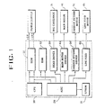
- An ink-jet printer has a CPU 10 for receiving a signal form a computer (not shown) through a printer interface.
- the CPU reads a system program from EPROM 11 which stores an initial value set for operating the printer and the system.
- the CPU outputs a control signal according to the program content.
- ROM 12 holds a control program and several fonts.
- RAM 13 temporarily stores data during the operation of the systems.
- An ASIC circuit part 20, in which most of the GPU-controlling logic circuits are realized in an ASIC form, transmits data from CPU 10 to the majority of the circuits around CPU 10.
- a head driver controls the operation of an ink cartridge 31 in response to the control signal of the CPU 10 which is transmitted from the ASIC circuit part 20.
- a maintenance driving circuit 40 protects the nozzle of the ink cartridge 31 from exposure to air and drives a driving circuit of a maintenance motor 41.
- a carriage motor driving circuit 50 controls the operation of a carriage return driving motor 51.
- a line feed motor driving circuit 60 controls the operation of line feed motor 61 for feeding/discharging paper by using a stepping motor.
- the ink cartridge 31 sprays fine ink drops through a plurality of openings in the nozzle, and thus forms dots.
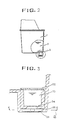
- Ink cartridge 31 will be described in detail.
- the ink cartridge includes a head 3. Ink 2 is absorbed through a sponge in case 1 which forms the external profile of the container.
- the head 3 has a filter 32 for eliminating impurity materials mixed with the ink.
- An ink stand pipe chamber 33 contains ink filtered through the filter 32.
- An ink via 34 supplies ink transmitted through the ink stand pipe chamber 33 to an ink heating part and a chip 35 having a chamber.
- a nozzle plate 36 has a plurality of orifices for expelling ink transmitted from the ink via 34, from the heating part (not shown) to a print media.
- the head 3 includes the ink via 34 for supplying ink to an ink chamber (not shown) between the nozzle plate 36 and the chip 35.
- a plurality of ink channels 37 supplies ink from the ink via 34 to each opening of the nozzle plate 36.
- a plurality of spraying parts 35 is provided for spraying ink transmitted through the ink channels 37.
- a plurality of electrically connecting means 38 is provided for supplying power to the plurality of chips 35.
- the head 3 includes a resistor layer 103 formed on an oxide layer (SiO 2 ) 102 on a silicon substrate 101 by an oxidation process when heated by electrical energy.
- Two electrodes 104 and 104' formed on the resistor layer 103 one provided with an electrical connection.
- a protective layer including several layers is provided for preventing the heating part 103 formed on resistor layers 104 and 104' and resistor layer 103 from being etched and deformed by a chemical reaction with the ink.
- An ink chamber 107 is provided for generating bubbles in the ink from the heat of the heated part 105.
- An ink channel 108 allows ink to flow from the ink via to the ink chamber 107.
- An ink barrier 109 plays the role of a wall to form a space used for leading ink transmitted through the ink channel to the ink chamber 107.
- a nozzle plate 111 has a plurality of orifices 110 for spraying ink pushed out as a result of the volume variation caused by generation of bubbles in the ink chamber 107.
- Nozzle plate 111 and the heated portion 105 are spaced apart at regular intervals to face each other.
- a pair of electrodes 104 and 104' are connected to an externally electrically connected terminal bumper (not shown) and this bumper is connected to a head controller (not shown) so that the ink is sprayed from each position through the nozzle openings.
- Each of the heating portions has an ink barrier 109 for guiding the ink from the side, and this ink barrier 109 is connected to a common ink via to guide the ink from the ink container.
- the conventional ink spray device sprays as follows.
- Head driver 30 transmits electrical energy to a pair of electrodes 104 and 104' placed where the desired characters will be printed in response to the control command of CPU 10 which receives the printing command through the printer interface.
- the surface of the heating portion 105 is heated up to 500 to 550°C, and heat is conducted to the plurality of protective layers 106. At this point heat is applied to the ink in wetting contact with the protective layers.
- the distribution of the bubbles generated by the vapour pressure is highest in the centre, regarding the centre of the heating part 105 about a symmetrical axis.
- ink expanded and discharged out of the openings of the nozzle plate, is sprayed onto print media in the form of a drop due to the surface tension, and this forms an image. Due to the internal pressure drop following the decrease in volume of the bubbles, ink is re-charged from the container via the ink via.
- the above-mentioned conventional ink spraying method has the following problems.
- the content of the ink may be affected by the thermal variation.
- the life of the internal components is decreased due to the impact wave from the bubbles. These may cause dissatisfactory use instead of the desired high quality printing.
- the ink, the protective layer 106 of the resistor 103 and the two electrodes 104 and 104' inter-act electrically with each other, and, accordingly, corrosion occurs by ion exchange at the border layer of the heating part 105 and the two electrodes 104 and 104', thereby decreasing the lifetime of the head.
- the shape of the drop affects its direction of travel its roundness and the uniformity of the quantity of ink in the drop according to the shape of the bubbles, and therefore this affects the printing quality.
- First and second electrodes 201 and 202 are formed on the upper/lower surfaces of a nozzle plate 200, so that a nozzle 203 is fabricated, using an excimer laser.
- the nozzle 203 is directly connected with an ink cartridge (not shown) to cause conductive ink to flow into the nozzle 203 under capillary action.
- High voltage is applied to the two electrodes 201 and 202 to heat and evaporate the conductive ink, and thus to spray the ink in the nozzle towards a paper due to the vapour pressure.
- nozzle 203 is in the form of a taper whose upper sectional area making contact with the paper is greater than the lower sectional area.
- the voltage applied to the two electrodes is about 1000-3000V, and is capable of operating up to 10kHz.
- the ink in the nozzle is heated using a high voltage to spray the ink in the nozzle onto the paper, the length of the nozzle is long. Furthermore, the sectional area of the lower electrode, namely hole D of the second electrode, connected to the nozzle is greater than a sectional area D' of the lower part of the nozzle. Therefore, when a voltage is applied to each electrode, it Is difficult to centre the current density and a high voltage is required. Moreover, since the nozzle plate having those two electrodes and the nozzle part is thick, the processing time is long, and production costs are accordingly increased.
- an inkjet printing head comprising an ink chamber and a nozzle plate with an orifice through which ink is ejected, the plate having an inner surface facing the ink chamber which comprises a first electrode and an outer exposed surface comprising an insulating layer, the ink chamber comprising a second electrode, the electrodes being electrically isolated from each other and adpated to;pass current through the ink in the ink chamber so as to create bubbles in the ink and thus to eject ink through the orifice.
- the nozzle plate comprises a conductive layer constituting the first electrode.
- the conductive layer is shaped to correspond with the shape of the portion of the second electrode in wetting contact with the ink, so as to centre the flow of current in the ink chamber.
- the portion of the conductive layer in wetting contact with the ink is of comparable size to the area of the second electrode in wetting contact with the ink.
- head in which the first electrode surrounds the orifice.
- a head in which the first electrode is in the form of a ring surrounding the orifice.
- a head in which the ring is substantially circular.
- a head in which the insulating layer substantially covers the first electrode.
- the insulating layer is of substantially constant thickness.
- a head in which the first electrode forms a part of an inner face of the orifice in the nozzle plate.
- a head in which the insulating layer forms an outer part of an inner face of the orifice of the nozzle plate.
- the second electrode constitutes an inner face of the ink chamber opposite the orifice and the second electrode is spaced from the first electrode away from the orifice.
- a head in which the geometry of the ink chamber and the electrodes is such that when, in use, a first bubble is produced current flow is restricted resulting in an increase in current density in the ink encouraging further bubble generation.
- the orifice in the nozzle plate has a smaller average cross sectional area then the average cross-sectional area of the ink chamber.
- a head in which a plurality of ink chambers are provided and the first electrode is a common electrode.
- the conductive layer is in the form of a series of interconnected substantially circular rings, the rings surrounding the multiple orifices in the nozzle plate.
- a head comprising:
- a head comprising a layer forming ink chamber walls or barriers formed between the first and second electrodes for electrically isolating from each other the regions in contact with the ink of adjacent individual second electrodes and for directing the ink out of the orifice.
- the ink has a predetermined resistivity value.
- the ink contains sodium chloride for conductive activation.
- the first and/or second electrodes comprise an alloy of nickel and platinum.
- a head in which voltages applied to the first and second electrodes for bubble generation are in the range of 0V to 100V.
- a head in which electric currents applied to the first and second electrodes are in the range of 0A to 5A.
- a head in which the orifice has a sectional area facing toward a print media smaller than a sectional area facing toward the ink chamber.
- a head in which the intermediate insulating layer is bonded to the nozzle plate by glue.
- a head in which the intermediate insulating layer is sealed to the nozzle plate by thermal welding.
- a head in which the conductive layer surrounds the profile of multiple openings in the nozzle plate.
- a head comprising a nozzle plate with an orifice through which ink is ejected, the plate having an inner surface facing the ink chamber which comprises a first electrode, the ink chamber comprising a second electrode, the electrodes being electrically isoldated from each other and adapted to pass current through the ink in the ink chamber so as to create bubbles in the ink and thus to eject ink through the orifice, the electrodes being arranged so as to centre the flow of current in the ink chamber.
- the conductive layer is shaped to correspond with the shape of the portion of the second electrode in wetting contact with the ink so as to centre the flow of current in the ink chamber.
- the portion of the conductive chamber in wetting contact with the ink is of comparable size to the area of the second electrode to wetting contact with the ink.
- a head in which the conductive layer is in the form of a ring, preferably a circle, surrounding multiple openings in the nozzle plate corresponding to multiple ink chambers.
- the current flow through the conductive ink in the ink chamber is straightened by the influence of the conductive layer of the nozzle plate.
- a spray device for an inkjet printer in which a surface of a nozzle plate is used for a common electrode and is equally coated with an insulating layer, and an inner side, namely, a side of an ink chamber is made of a conductor, so that the spray device has a simple structure, is easier to make and reduces the loss of power.
- the spray device and method of the invention are arranged to centre the current density and restore the loss of power so low voltage operation is possible and the uniformity in the positions of the bubbles is improved and thus the drops are printed straight.
- a spray device comprising a coating of a conductive layer around a predetermined opening of a nozzle plate to stabilize a flow of a current density generated in a conductive ink by electrical energy applied to two electrodes in a chamber of the ink spray device, so as to enhance the quality of printing.
- a spray device comprising a nozzle plate structured into multiple layers by forming a surface wetting with an ink in an ink chamber in a nozzle plate as a conductive layer made of nickel and/or platinum alloy, and also forming the other surface facing the print media as an insulating layer, to thereby centre the energy generated through the conductive ink, and reduce power leakage.
- the invention provides a spray device of an inkjet printer capable of reducing energy leakage by structuring as an insulating layer a predetermined area which does not wet with the ink in a nozzle plate acting as a common electrode in a spray device.
- the nozzle plate is electrically separated from the individual electrode, formed on the different layers, and thus used for the common electrode to thereby generate bubbles in the ink, the surface wetting with the ink is formed as the conductive layer, and the other surface facing towards media is formed as the insulating layer.
- a method of ejecting ink from an inkjet printer head as herein described comprising applying voltages to the two electrodes producing bubbles created by electrical energy supplied to the electrodes so as to spray ink out of the orifice.
- a spray device of an inkjet printer comprising a plurality of individual electrodes formed on an oxide layer SiO 2 on a silicon substrate and having a predetermined portion wetting with an ink to generate bubbles in the ink and the remaining portions serving as an insulating layer.
- a nozzle plate made of a plurality of openings for spraying an ink to media.
- conductive layers surround the openings.
- insulating layers cover the conductive layers.
- the nozzle plate is separated from the plurality of individual electrodes and formed on a different layer.
- the nozzle plate has a predetermined portion wetting with the ink serving as a common electrode to generate bubbles in the ink with electrical energy.
- a barrier serves as a guiding wall and electrically separates the portion wetting with the ink in the individual electrodes from the adjacent individual electrodes and supplies the ink transmitted from an ink via through an ink channel to an ink chamber.
- there is an ink chamber for receiving the ink through the barrier and generating bubbles with the current density between the individual electrodes and the nozzle plate.
- electrical connecting means for supplying electrical energy to the individual electrodes and the nozzle plate.
- a method of ejecting ink from the inkjet printer head as herein described comprising applying voltages to the two electrodes producing bubbles created by electrical energy supplied to the electrodes so as to spray ink out of the orifice.
- FIG. 1 is a block diagram illustrating the structure of a general inkjet printer.
- FIG. 2 is a schematic sectional view of an ink cartridge.
- FIG. 3 is an enlarged sectional view of a spray part in a conventional spray device.
- FIG. 4 is a plan sectional view taken along lines E-E of FIG. 3 in a direction A.
- FIG. 5 is an enlarged sectional view of a conventional spray device taken along an axis of F to F of FIG.4 seen in direction B.
- FIG. 6 is an exemplified view of a conventional ink spraying method.
- FIG. 7 illustrates a nozzle plate part of an improved conventional spray device.
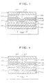
- FIG. 8 is an enlarged sectional view of a spray device according to an embodiment of the invention.
- FIG. 9 is an enlarged sectional view of a spray device according to another embodiment of the invention.
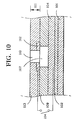
- FIG. 10 is a top sectional view of the nozzle plate of FIG. 8.
- FIG. 11 is an exemplified view illustrating a method for spraying ink according to the invention.
- FIG. 12 is an exemplified view illustrating a method for spraying ink according to the invention.
- a spray device for an inkjet printer includes a plurality of individual electrodes 104 formed on an oxide layer (SiO 2 ) 102 on a silicon substrate support 101.
- the electrodes 104 have predetermined portions which wet with ink to generate bubbles in the ink and the remaining portions are insulated.
- a nozzle plate 111 has a plurality of openings 110 for spraying ink onto media.
- Conductive layer 112 surrounds the openings.
- Insulating layer 113 covers the conductive layer.
- the nozzle plate is separated from the plurality of individual electrodes 104 and is formed on a different layer.
- the nozzle plate has a predetermined portion which wets with the ink and serves as a common electrode to generate bubbles in the ink with electrical energy supplied from the individual electrodes.
- a barrier 109 serves as a guiding wall, which electrically separates the portion of individual electrodes 104 wetting with the ink from adjacent individual electrodes 104, and supplies the ink transmitted from an ink via through an ink channel to an ink chamber.
- the barrier 109 increases a spraying force spraying the ink to the openings in the nozzle plate and straightening the direction of the vapour pressure.
- An ink chamber 107 receives the ink through the barrier 109 and generates bubbles by the current concentration between the individual electrodes 104 and the nozzle plate 111.
- An electrical connecting means is provided for supplying electrical energy to the individual electrodes 104 and the nozzle plate 111.
- the entire surface of the nozzle plate 111 is equally coated on one side by an insulating layer 113 of, in this embodiment, substantially constant thickness. Its internal side, namely, the side to the ink chamber 107 is structured as a conductor, so that its manufacture and structure are simple, and the loss of power is reduced.
- the conductive layer is preferably substantially equal in size or just larger than ink chamber 107, thus not overlapping with other neighbouring chambers. It can prevent concentration of current density and loss of power. Therefore, the invention can be driven with a low voltage, and the bubbles are formed at the same location, enhancing the straightness of drops.
- the material of the individual electrodes and the nozzle plate is an alloy of nickel and/or platinum to prevent corrosion when in contact with the conductive ink.
- the printing method of the printer is generally the same as the conventional one.
- the spray device of the inkjet printer will be described here.
- a head driver (not shown) supplies electrical energy to the corresponding individual electrode.
- a voltage is applied to the electrodes at the corresponding position, namely, to the individual electrodes 104, and simultaneously a voltage of reverse polarity is applied to the conductive layer 112 of the nozzle plate 111 as a common electrode.
- the voltage supplied is below 100V DC, and the current flowing in each electrode is below 5A.
- the current flows through the conductive ink in wetting contact with the electrodes to electrically conduct between the individual electrodes and the common electrode.
- the ink contains constant resistance components.
- the sectional area of the paper side T' is structured to be smaller than that T of the ink chamber side. Therefore, the straightness of the ink drop is increased.
- a spray device according to the invention with a different structure will be described below with reference to FIG. 10.
- the structure of the embodiment of FIG. 10 is different from that of FIG. 8 in that the conductive layer 112 formed in the nozzle plate 111, having a plurality of openings 110, is a donut form.
- This conductive layer 112 surrounds the openings 110. Therefore, the flow of the current density generated in the ink chamber 107 is not dissipated by the nozzle plate, so that the bubbles are more stably generated, and thus the printing is highly qualified.
- FIG. 11 is a top sectional view of the nozzle plate 110 of FIG. 10, showing its openings from above.
- the conductive layer 112 surrounds openings 110, as in the form of a donut.
- FIG. 12 A specific method of forming the bubbles and printing using the device of FIGS. 8 to 10, is illustrated below with reference to FIG. 12.
- Power of different polarity is supplied to the conductive layers of the individual electrodes 104 and the nozzle plate 111.
- a DC voltage is applied across the individual electrode 104 and the nozzle plate, a difference of current density occurs in the direction from the individual electrodes 104 to the nozzle plate.
- the predetermined heat generated by the current density difference in the chamber 107 is determined by the internal current and resistance of the ink.
- the ink spraying and recharging operations are performed to realize an intended image on the print media.
- the electrical energy applied between the individual electrodes 104 wetting with the ink in the ink chamber 107, and the conductive layer 112 of the nozzle plate 111 is converted into heat at a predetermined internal location through the conductive ink being an inter-medium, the ink is heated and evaporated by the heat, generating bubbles, and then sprayed to the openings 110.
- the conductive layer 112 of the nozzle plate 111 is structured as a conductive layer in which only a part corresponding to the individual electrode 104 wetting with the ink, is electrically conductive, so that the current density for each unit is centred, facilitating high frequency operation.
- insulating layer 113 of the nozzle plate 111 prevents power leakage which may occur because of transporting print media of high-temperature, high-dampness and low-resistance irregularly, thereby enhancing its efficiency. Such print media can contaminate and impair the performance of the print head.
- the invention electrically separates the nozzle plate operating as a common plate from the individual electrodes by using the insulating layer to apply a different polarity of power to the two electrodes, so that the current flow by the current density difference is used for generating bubbles, and the heat is generated by the internal current and resistor components in the ink. Accordingly, the invention does not require a protective layer for protecting the internal electrodes such as in a conventional head, and therefore there is no damage of the surface of that layer due to the heat generated from the heater part.
- the bubbles are successively generated in the ink according to the Joule's law.
- the individual electrodes and the nozzle plate are electrically isolated so that the current density for generating the bubble increases, optimising the vapour pressure.
- the straightness of trajectory of the ejected ink drops and the constancy of the spraying speed are optimised.
- the current density is increased.
- the bubbles are easily generated.
- the structure is simple facilitating high frequency ink spraying and also increasing yield in manufacturing procedures.
Landscapes
- Particle Formation And Scattering Control In Inkjet Printers (AREA)
Applications Claiming Priority (2)
| Application Number | Priority Date | Filing Date | Title |
|---|---|---|---|
| KR9627127 | 1996-07-04 | ||
| KR1019960027127A KR100205747B1 (ko) | 1996-07-04 | 1996-07-04 | 잉크젯프린터의 분사장치 및 분사방법 |
Publications (2)
| Publication Number | Publication Date |
|---|---|
| EP0816093A2 true EP0816093A2 (fr) | 1998-01-07 |
| EP0816093A3 EP0816093A3 (fr) | 1998-11-04 |
Family
ID=19465526
Family Applications (1)
| Application Number | Title | Priority Date | Filing Date |
|---|---|---|---|
| EP97304902A Ceased EP0816093A3 (fr) | 1996-07-04 | 1997-07-04 | Dispositif et procédé à jet d'encre |
Country Status (4)
| Country | Link |
|---|---|
| US (1) | US6364464B1 (fr) |
| EP (1) | EP0816093A3 (fr) |
| JP (1) | JP2880146B2 (fr) |
| KR (1) | KR100205747B1 (fr) |
Families Citing this family (3)
| Publication number | Priority date | Publication date | Assignee | Title |
|---|---|---|---|---|
| US6756296B2 (en) * | 2001-12-11 | 2004-06-29 | California Institute Of Technology | Method for lithographic processing on molecular monolayer and multilayer thin films |
| TWI265095B (en) * | 2005-08-16 | 2006-11-01 | Ind Tech Res Inst | Nozzle plate |
| TWI322085B (en) * | 2007-03-07 | 2010-03-21 | Nat Univ Tsing Hua | Micro-droplet injector apparatus having nozzle arrays without individual chambers and ejection method of droplets thereof |
Family Cites Families (17)
| Publication number | Priority date | Publication date | Assignee | Title |
|---|---|---|---|---|
| IT1129356B (it) * | 1980-10-31 | 1986-06-04 | Olivetti Ing C Spa | Dispositivo di stampa a getto selettivo di inchiostro |
| US4275290A (en) * | 1978-05-08 | 1981-06-23 | Northern Telecom Limited | Thermally activated liquid ink printing |
| US4164745A (en) * | 1978-05-08 | 1979-08-14 | Northern Telecom Limited | Printing by modulation of ink viscosity |
| FR2448979B1 (fr) | 1979-02-16 | 1986-05-23 | Havas Machines | Dispositif destine a deposer sur un support des gouttes d'encre |
| IT1144294B (it) * | 1981-07-10 | 1986-10-29 | Olivetti & Co Spa | Dispositivo di stampa getto selettivo d inchiostro |
| US4893191A (en) * | 1986-09-19 | 1990-01-09 | Victor Company Of Japan, Ltd. | Gradation control device for thermal ink-transfer type printing apparatus |
| CH677755A5 (fr) * | 1988-10-05 | 1991-06-28 | Battelle Memorial Institute | |
| JPH02185446A (ja) * | 1989-01-12 | 1990-07-19 | Nec Corp | インクジェットプリンタ |
| JPH02270556A (ja) * | 1989-04-13 | 1990-11-05 | Nec Corp | インクジェットプリンタ |
| US5434606A (en) * | 1991-07-02 | 1995-07-18 | Hewlett-Packard Corporation | Orifice plate for an ink-jet pen |
| US5434607A (en) * | 1992-04-02 | 1995-07-18 | Hewlett-Packard Company | Attachment of nozzle plate to flexible circuit for facilitating assembly of printhead |
| JP3408292B2 (ja) * | 1992-09-09 | 2003-05-19 | ヒューレット・パッカード・カンパニー | プリントヘッド |
| US5378137A (en) * | 1993-05-10 | 1995-01-03 | Hewlett-Packard Company | Mask design for forming tapered inkjet nozzles |
| US5368683A (en) * | 1993-11-02 | 1994-11-29 | Xerox Corporation | Method of fabricating ink jet printheads |
| JPH08104006A (ja) * | 1994-10-06 | 1996-04-23 | Matsushita Electric Ind Co Ltd | インクジェット装置 |
| JPH08192530A (ja) * | 1995-01-18 | 1996-07-30 | Olympus Optical Co Ltd | 静電記録ヘッド及びその製造方法 |
| JPH0971003A (ja) * | 1995-06-30 | 1997-03-18 | Minolta Co Ltd | 画像形成装置用の帯電装置 |
-
1996
- 1996-07-04 KR KR1019960027127A patent/KR100205747B1/ko not_active Expired - Fee Related
-
1997
- 1997-07-04 JP JP9194999A patent/JP2880146B2/ja not_active Expired - Lifetime
- 1997-07-04 EP EP97304902A patent/EP0816093A3/fr not_active Ceased
- 1997-07-07 US US08/888,650 patent/US6364464B1/en not_active Expired - Fee Related
Also Published As
| Publication number | Publication date |
|---|---|
| JPH1086378A (ja) | 1998-04-07 |
| KR980008575A (ko) | 1998-04-30 |
| US6364464B1 (en) | 2002-04-02 |
| JP2880146B2 (ja) | 1999-04-05 |
| KR100205747B1 (ko) | 1999-07-01 |
| EP0816093A3 (fr) | 1998-11-04 |
Similar Documents
| Publication | Publication Date | Title |
|---|---|---|
| US6074043A (en) | Spray device for ink-jet printer having a multilayer membrane for ejecting ink | |
| EP0677387B1 (fr) | Couche de base pour tête à jet d'encre et tête à jet d'encre l'utilisant | |
| CA1275855C (fr) | Tete d'imprimante au jet d'encre | |
| US6890062B2 (en) | Heater chip configuration for an inkjet printhead and printer | |
| EP0816083A2 (fr) | Dispositif et procédé de pulvérisation d'encre | |
| US8376522B2 (en) | Liquid ejection head and printing apparatus | |
| KR101684727B1 (ko) | 열 저항기 유체 토출 어셈블리 | |
| KR100205745B1 (ko) | 잉크젯 프린터의 분사 장치 및 분사 방법 | |
| EP0816093A2 (fr) | Dispositif et procédé à jet d'encre | |
| US6048051A (en) | Ink-jet printing method and ink-jet printing apparatus using dielectric migration force | |
| US6332668B1 (en) | Apparatus for and method of ejecting ink of an ink-jet printer | |
| KR100205746B1 (ko) | 잉크젯 프린터의 분사 장치 및 분사 방법 | |
| KR100209522B1 (ko) | 잉크젯 프린터의 분사장치 및 분사방법 | |
| JPH04347647A (ja) | インクジェット記録装置 | |
| JPH09216356A (ja) | インクジェットプリンタのインク噴射装置及び方法 | |
| US6106103A (en) | Ink-jet spraying device and method using ultrasonic waves | |
| JP2002254645A (ja) | 印字ヘッド | |
| KR100438714B1 (ko) | 잉크젯 프린트헤드의 제조방법 | |
| JPH08216411A (ja) | サーマルインクジェット用サーマルヘッド基板および その駆動方法 | |
| JPH06262763A (ja) | インクジェットヘッド及びその製造方法 | |
| JPH0516362A (ja) | 液体吐出装置 |
Legal Events
| Date | Code | Title | Description |
|---|---|---|---|
| PUAI | Public reference made under article 153(3) epc to a published international application that has entered the european phase |
Free format text: ORIGINAL CODE: 0009012 |
|
| AK | Designated contracting states |
Kind code of ref document: A2 Designated state(s): DE FR GB IT |
|
| 17P | Request for examination filed |
Effective date: 19980205 |
|
| PUAL | Search report despatched |
Free format text: ORIGINAL CODE: 0009013 |
|
| AK | Designated contracting states |
Kind code of ref document: A3 Designated state(s): AT BE CH DE DK ES FI FR GB GR IE IT LI LU MC NL PT SE |
|
| AKX | Designation fees paid |
Free format text: DE FR GB IT |
|
| 17Q | First examination report despatched |
Effective date: 19990819 |
|
| GRAG | Despatch of communication of intention to grant |
Free format text: ORIGINAL CODE: EPIDOS AGRA |
|
| RAP1 | Party data changed (applicant data changed or rights of an application transferred) |
Owner name: SAMSUNG ELECTRONICS CO LTD. |
|
| STAA | Information on the status of an ep patent application or granted ep patent |
Free format text: STATUS: THE APPLICATION HAS BEEN REFUSED |
|
| 18R | Application refused |
Effective date: 20010628 |