EP0816901A1 - Anordnung zur Einstellung des Abstandes zwischen Glassubstraten - Google Patents
Anordnung zur Einstellung des Abstandes zwischen Glassubstraten Download PDFInfo
- Publication number
- EP0816901A1 EP0816901A1 EP97110572A EP97110572A EP0816901A1 EP 0816901 A1 EP0816901 A1 EP 0816901A1 EP 97110572 A EP97110572 A EP 97110572A EP 97110572 A EP97110572 A EP 97110572A EP 0816901 A1 EP0816901 A1 EP 0816901A1
- Authority
- EP
- European Patent Office
- Prior art keywords
- glass panel
- supporting plate
- plate
- closed space
- glass
- Prior art date
- Legal status (The legal status is an assumption and is not a legal conclusion. Google has not performed a legal analysis and makes no representation as to the accuracy of the status listed.)
- Granted
Links
- 239000011521 glass Substances 0.000 title claims abstract description 81
- 239000000758 substrate Substances 0.000 title claims abstract description 16
- 125000006850 spacer group Chemical group 0.000 claims abstract description 37
- 239000012530 fluid Substances 0.000 claims abstract description 6
- 229920005989 resin Polymers 0.000 claims description 7
- 239000011347 resin Substances 0.000 claims description 7
- 239000004744 fabric Substances 0.000 claims description 6
- 229920002379 silicone rubber Polymers 0.000 claims description 3
- 239000000919 ceramic Substances 0.000 description 6
- 238000000034 method Methods 0.000 description 5
- 239000000463 material Substances 0.000 description 4
- 238000007789 sealing Methods 0.000 description 4
- 239000004973 liquid crystal related substance Substances 0.000 description 3
- 229910052782 aluminium Inorganic materials 0.000 description 2
- XAGFODPZIPBFFR-UHFFFAOYSA-N aluminium Chemical compound [Al] XAGFODPZIPBFFR-UHFFFAOYSA-N 0.000 description 2
- 229910000838 Al alloy Inorganic materials 0.000 description 1
- XUIMIQQOPSSXEZ-UHFFFAOYSA-N Silicon Chemical compound [Si] XUIMIQQOPSSXEZ-UHFFFAOYSA-N 0.000 description 1
- 239000000853 adhesive Substances 0.000 description 1
- 230000001070 adhesive effect Effects 0.000 description 1
- 239000004760 aramid Substances 0.000 description 1
- 229920003235 aromatic polyamide Polymers 0.000 description 1
- 239000011324 bead Substances 0.000 description 1
- 239000004020 conductor Substances 0.000 description 1
- 229920001973 fluoroelastomer Polymers 0.000 description 1
- 239000003779 heat-resistant material Substances 0.000 description 1
- 229910052751 metal Inorganic materials 0.000 description 1
- 239000002184 metal Substances 0.000 description 1
- 239000004033 plastic Substances 0.000 description 1
- 229910052710 silicon Inorganic materials 0.000 description 1
- 239000010703 silicon Substances 0.000 description 1
- 239000010935 stainless steel Substances 0.000 description 1
- 229910001256 stainless steel alloy Inorganic materials 0.000 description 1
Images
Classifications
-
- B—PERFORMING OPERATIONS; TRANSPORTING
- B32—LAYERED PRODUCTS
- B32B—LAYERED PRODUCTS, i.e. PRODUCTS BUILT-UP OF STRATA OF FLAT OR NON-FLAT, e.g. CELLULAR OR HONEYCOMB, FORM
- B32B37/00—Methods or apparatus for laminating, e.g. by curing or by ultrasonic bonding
- B32B37/10—Methods or apparatus for laminating, e.g. by curing or by ultrasonic bonding characterised by the pressing technique, e.g. using action of vacuum or fluid pressure
- B32B37/1054—Regulating the dimensions of the laminate, e.g. by adjusting the nip or platen gap
-
- B—PERFORMING OPERATIONS; TRANSPORTING
- B32—LAYERED PRODUCTS
- B32B—LAYERED PRODUCTS, i.e. PRODUCTS BUILT-UP OF STRATA OF FLAT OR NON-FLAT, e.g. CELLULAR OR HONEYCOMB, FORM
- B32B37/00—Methods or apparatus for laminating, e.g. by curing or by ultrasonic bonding
- B32B37/10—Methods or apparatus for laminating, e.g. by curing or by ultrasonic bonding characterised by the pressing technique, e.g. using action of vacuum or fluid pressure
- B32B37/1018—Methods or apparatus for laminating, e.g. by curing or by ultrasonic bonding characterised by the pressing technique, e.g. using action of vacuum or fluid pressure using only vacuum
-
- G—PHYSICS
- G02—OPTICS
- G02F—OPTICAL DEVICES OR ARRANGEMENTS FOR THE CONTROL OF LIGHT BY MODIFICATION OF THE OPTICAL PROPERTIES OF THE MEDIA OF THE ELEMENTS INVOLVED THEREIN; NON-LINEAR OPTICS; FREQUENCY-CHANGING OF LIGHT; OPTICAL LOGIC ELEMENTS; OPTICAL ANALOGUE/DIGITAL CONVERTERS
- G02F1/00—Devices or arrangements for the control of the intensity, colour, phase, polarisation or direction of light arriving from an independent light source, e.g. switching, gating or modulating; Non-linear optics
- G02F1/01—Devices or arrangements for the control of the intensity, colour, phase, polarisation or direction of light arriving from an independent light source, e.g. switching, gating or modulating; Non-linear optics for the control of the intensity, phase, polarisation or colour
- G02F1/13—Devices or arrangements for the control of the intensity, colour, phase, polarisation or direction of light arriving from an independent light source, e.g. switching, gating or modulating; Non-linear optics for the control of the intensity, phase, polarisation or colour based on liquid crystals, e.g. single liquid crystal display cells
- G02F1/133—Constructional arrangements; Operation of liquid crystal cells; Circuit arrangements
- G02F1/1333—Constructional arrangements; Manufacturing methods
- G02F1/1339—Gaskets; Spacers; Sealing of cells
Definitions
- This invention relates to an apparatus for setting a uniform gap of a liquid crystal panel by pressing it by the evacuation method.
- the panel is comprised of two glass substrates that have transparent electrodes on their inner surfaces and a thermo-setting resin therebetween.
- a glass substrate means a substrate made of glass or other material (such as a plastic) suitable for a liquid crystal panel.
- glass panel means a panel made of such glass substrates.
- Japanese Patent Laying-Open Publication No. 8-26788 discloses an apparatus for setting a gap of a glass panel by the evacuation method.
- gaskets are disposed on and under the glass panel to prevent the glass substrates from shifting.
- the panel since the glass panel is supported at its periphery by the gaskets, the panel tends to deflect due to its weight, thereby causing the glass substrates to shift.
- the apparatus can be used only for glass panels of a definite size. Therefore apparatuses of different sizes must be used for glass panels of different sizes.
- Japanese Patent Publication No. 3-4888 teaches an apparatus for setting a gap of a liquid crystal panel by the evacuation method to indirectly press it.
- a buffer is disposed under the lower surface of the panel, the rate of thermal expansion of a flexible sheet, which contacts the upper surface of the panel, and the rate of thermal expansion of a mold, which contacts the lower surface of it, differ due to heaters embedded in the mold.
- the forces which confine the upper and lower glass substrates differ, thereby allowing them to have differing rates of expansion. This causes them to shift.
- This invention aims to provide an apparatus for setting gaps of glass panels of different sizes wherein the relative shift of the glass substrates is prevented.
- the apparatus of the present invention for setting a gap of a glass panel having two glass substrates includes an annular spacer for surrounding the glass panel, a supporting plate for supporting the glass panel and the annular spacer, the width of the supporting plate being greater than that of the annular spacer, a pair of opposing columns for receiving the supporting plate, a flexible sheet disposed on the annular spacer, the width of the sheet being greater than that of the annular spacer so as to be associated with the supporting plate to enclose the glass panel, means for defining a closed space between the supporting plate and the flexible sheet, a passage in fluid communication with the closed space, and means connected to the passage for evacuating the closed space.
- the annular spacer is changed to a small or large one.
- the passage is disposed outside the annular spacer and the spacer has a notch therein as a passage through which the closed space is evacuated by the evacuating means.
- a rigid plate is disposed between the flexible sheet and the glass plate or between the glass plate and the supporting plate, or both.
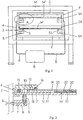
- Fig. 1 is a schematic front view of one embodiment of the apparatus of the present invention.
- Fig. 2 is a cross-sectional view in an enlarged scale of the part A in Fig. 1.
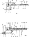
- Fig. 3 is a view similar to Fig. 2, showing an additional press plate.
- Fig. 4 is also a view similar to Fig. 2, showing additional rigid plates.
- Figs. 1 and 2 an oven with internal air circulation M is disposed. Outside the oven M a frame F is disposed.
- the frame F has a pair of aluminum opposing columns 2, 2A installed on a floor near the oven M, and a tie beam 3 connecting the columns 2, 2A.
- two glass panels (upper and lower panels) are supported by the frame in two levels. The structure of each level is the same. Thus the structure of the upper level, especially the structure of a portion A of the upper level, will now be explained.
- a pair of brackets 4, 4A are secured to the columns 2, 2A.
- the brackets 4, 4A are long enough to receive a ceramic supporting plate 11.
- a pair of brackets 6, 6A are also secured to the columns 2, 2A.
- a silicon suction pad 5 (5A) is attached to the distal end of each bracket 6 (6A) such that the level (initial position) of the top of the bracket 6 (6A) is slightly higher than that of the bottom of the supporting plate 11 (higher than the level of the top of the supporting-plate-receiving portion of the bracket 4).
- the supporting plate 11 has suction throughbores 10, 10A, each of which is connected to one end of a passage 7 formed in the pad 5 and bracket 6. The other end 8 of the passage 7 is connected to a vacuum pump 9 (Fig. 1).
- the glass panel W is placed on the supporting plate 11.
- the glass panel W includes upper and lower glass substrates 20, 21, which are spaced apart by spherical spacer blocks 22.
- a thermo-setting sealer 23 is applied to the inner periphery of the glass substrates 20, 21.
- An aluminum annular spacer 12 is disposed on the supporting plate 11 so that it surrounds the glass panel W.
- the spacer 12 is formed in a size (width) suitable for the glass panel W of a definite size, and it has a thickness slightly greater than that of the glass panel W.
- the thickness of the spacer 12 may be in a range of plus or minus 0.5 mm of the thickness of the glass panel.
- the spacer 12 has notches (not shown) therein which act as suction passages.
- a flexible, heat-resistant silicon-rubber sheet or fluororubber sheet 14 which has a width greater than that of the annular spacer 12, is put on the annular spacer 12 so that it encloses the glass panel W with the associated supporting plate 11.
- the flexible sheet 14 is secured to an annular sealing block 13 by a plurality of vises 18 and beads 17.
- Annular sealing gaskets 15, 16 are embedded in the sealing block 13 to seal or to define a closed space between the flexible sheet 14 and supporting plate 11.
- the flexible sheet 14 is pressed against the glass panel W, to thereby set a gap.
- the apparatus and the glass panel are moved into the oven M and are heated (at a temperature of 150 °C) for a predetermined period of time (one to two hours), so that the sealer 23 hardens.
- the apparatus and the glass panel are moved out of the oven M and cooled to the ambient temperature. Then the evacuation is stopped, and the flexible sheet 14 is removed. Thus the gap-setting is completed. (In some cases the evacuation may be stopped before the panel is cooled.)
- the suction pad 5 is disposed under the supporting plate 11 and connected to the throughbore 10 formed in the plate 11.
- This arrangement may be changed so that a suction throughbore is formed in the annular sealing block 13, and so that the suction pad 5 and the bracket 6 are disposed above the block 13 so that the passage 7 is in fluid communication with the closed space between the flexible sheet 14 and the supporting plate 11.
- Fig. 3 shows a second embodiment of the apparatus of the invention.
- an additional press plate H is used.
- Other elements are the same or similar to those in the first embodiment. Thus the same reference numbers and letters are used for those elements.
- the press plate H is made of a rigid and plane ceramic having sufficient thermal conductivity. Thus when the glass panel W is put in the oven M, heat is well transmitted to the panel through the ceramic supporting plate 11 and the press plate H. Further, since the press plate H is plane, the atmospheric pressure uniformly presses the panel W through the press plate H.
- the thickness of the annular spacer 12 is slightly greater than the total thickness of the glass panel W and the press plate H. However, the thickness of the spacer 12 may be within a range of plus or minus 0.5 mm of the total thickness of the glass panel and the press plate. The gap-setting procedure will be carried out as in the first embodiment.
- Fig. 4 shows a third embodiment of the apparatus of the present invention.
- the annular spacer which is denoted by the number 32, is modified, and an additional press plate H and holding plate 11A are used.
- Other elements are the same as in the first embodiment, and the same reference numbers and letters are used for them.
- the press plate H has the same size as that of the glass panel W.
- the press plate is plane and rigid and made of a material having thermal conductivity.
- it may be ceramic or glass, each of which has a rate of thermal expansion nearly equal to that of the glass panel.
- any material having a rate within a range of 0.05 - 3 times that of glass may be used.
- stainless steel and aluminum alloys may be used if they are within that range.
- the holding plate 11A is made of a rigid, plane, and heat-conductive material such as glass or a ceramic.
- the holding plate 11A may be made of the same material as the press plate H.
- the annular spacer 32 is affixed to the supporting plate 11 by vises as in the drawing. It is affixed after the holding plate 11A is put on the supporting plate 11.
- the annular spacer 32 is notched at the inner, lower part so that it has a horizontally extending portion 33 to hold the holding plate 11A.
- each sheet Q is heat-resistant.
- it may be a sheet of fluoro-resin, silicon rubber, glass cloth or fluoro-resin impregnated glass cloth, or a porous sheet of any fluoro-resin.
- Each sheet Q may be merely inserted between the plates, or it may be glued to them by means of an adhesive.
- the thickness (height) of the lower portion (retracted portion) of the annular spacer 32 is slightly greater (by about 0.2 mm) than the total thickness of the holding plate 11A and the intermediate sheet Q.
- the thickness of the extending portion 33 of the spacer 32 is slightly greater than the total thickness of the glass panel W, the press plate H, and the intermediate sheets Q. However, it may be within a range of plus or minus 1.0 mm of the total thickness.
- the gap-setting procedure will be carried out as in the first embodiment.
- annular spacer When a small glass panel is treated, an annular spacer is used which extends inward further than shown in the drawing.
- the supporting plate may be of metal or a laminated plate of glass cloth layers or aramid cloth layers, or both, in which heat-resistant material is impregnated.
Landscapes
- Physics & Mathematics (AREA)
- Fluid Mechanics (AREA)
- Nonlinear Science (AREA)
- Mathematical Physics (AREA)
- Chemical & Material Sciences (AREA)
- Crystallography & Structural Chemistry (AREA)
- General Physics & Mathematics (AREA)
- Optics & Photonics (AREA)
- Joining Of Glass To Other Materials (AREA)
- Liquid Crystal (AREA)
Applications Claiming Priority (9)
| Application Number | Priority Date | Filing Date | Title |
|---|---|---|---|
| JP18880296A JPH1020266A (ja) | 1996-06-28 | 1996-06-28 | ギャップ出し治具 |
| JP188802/96 | 1996-06-28 | ||
| JP18880296 | 1996-06-28 | ||
| JP21529396 | 1996-07-26 | ||
| JP215293/96 | 1996-07-26 | ||
| JP21529396A JPH1039319A (ja) | 1996-07-26 | 1996-07-26 | ギャップ出し治具 |
| JP102539/97 | 1997-04-04 | ||
| JP10253997A JPH10282462A (ja) | 1997-04-04 | 1997-04-04 | ギャップ出し治具 |
| JP10253997 | 1997-04-04 |
Publications (2)
| Publication Number | Publication Date |
|---|---|
| EP0816901A1 true EP0816901A1 (de) | 1998-01-07 |
| EP0816901B1 EP0816901B1 (de) | 2002-01-09 |
Family
ID=27309733
Family Applications (1)
| Application Number | Title | Priority Date | Filing Date |
|---|---|---|---|
| EP97110572A Expired - Lifetime EP0816901B1 (de) | 1996-06-28 | 1997-06-27 | Anordnung zur Einstellung des Abstandes zwischen Glassubstraten |
Country Status (6)
| Country | Link |
|---|---|
| US (1) | US5904801A (de) |
| EP (1) | EP0816901B1 (de) |
| KR (1) | KR100491150B1 (de) |
| CN (1) | CN1140839C (de) |
| DE (1) | DE69709494T2 (de) |
| TW (1) | TW388748B (de) |
Cited By (2)
| Publication number | Priority date | Publication date | Assignee | Title |
|---|---|---|---|---|
| WO2002005018A1 (en) * | 2000-07-12 | 2002-01-17 | Daikin Industries, Ltd. | Porous sheet made of fluoropolymer and process for producing liquid-crystal display panel with the same |
| WO2003036162A1 (en) * | 2001-10-24 | 2003-05-01 | Koninklijke Philips Electronics N.V. | Optical element with foil held by underpressure, method of manufacture, and display unit with such element |
Families Citing this family (6)
| Publication number | Priority date | Publication date | Assignee | Title |
|---|---|---|---|---|
| JP3169864B2 (ja) * | 1997-09-18 | 2001-05-28 | 日本電気株式会社 | 液晶パネル製造装置 |
| US6266015B1 (en) | 2000-07-19 | 2001-07-24 | Harris Corporation | Phased array antenna having stacked patch antenna element with single millimeter wavelength feed and microstrip quadrature-to-circular polarization circuit |
| US6421012B1 (en) | 2000-07-19 | 2002-07-16 | Harris Corporation | Phased array antenna having patch antenna elements with enhanced parasitic antenna element performance at millimeter wavelength radio frequency signals |
| US6320546B1 (en) | 2000-07-19 | 2001-11-20 | Harris Corporation | Phased array antenna with interconnect member for electrically connnecting orthogonally positioned elements used at millimeter wavelength frequencies |
| US20110009813A1 (en) * | 2009-07-09 | 2011-01-13 | Medtronic Minimed, Inc. | Panning a display of a portable medical device |
| EP2333340A1 (de) * | 2009-12-07 | 2011-06-15 | Debiotech S.A. | Flexibles Element für Mikropumpe |
Citations (3)
| Publication number | Priority date | Publication date | Assignee | Title |
|---|---|---|---|---|
| EP0066136A1 (de) * | 1981-05-15 | 1982-12-08 | Nissan Motor Co., Ltd. | Verfahren zur Herstellung einer Anzeigevorrichtung mit einem flüssigen Anzeigemedium zwischen zwei Substraten |
| JPS5957221A (ja) * | 1982-09-28 | 1984-04-02 | Asahi Glass Co Ltd | 表示素子の製造方法及び製造装置 |
| US4923552A (en) * | 1987-06-12 | 1990-05-08 | Matsushita Electric Industrial Co., Ltd. | Method of producing liquid crystal display element |
Family Cites Families (10)
| Publication number | Priority date | Publication date | Assignee | Title |
|---|---|---|---|---|
| JPH0670940B2 (ja) * | 1988-12-15 | 1994-09-07 | 株式会社村田製作所 | セラミック積層成形体の製造方法 |
| JPH0824738B2 (ja) * | 1989-05-31 | 1996-03-13 | ユニバーサル販売株式会社 | スロットマシンの入賞制御方法 |
| US5242651A (en) * | 1990-07-25 | 1993-09-07 | Vought Aircraft Company | Pressure balanced processing of composite structures |
| DE69129944D1 (de) * | 1990-11-23 | 1998-09-10 | Akro Fireguard Prod Inc | Feuerfester reparaturflicken und verfahren zu seiner herstellung |
| US5116216A (en) * | 1991-02-28 | 1992-05-26 | The United States Of America As Represented By The Secretary Of The Navy | Apparatus for preparing thermoplastic composites |
| CA2091999C (en) * | 1991-09-06 | 1996-06-04 | Donald William Dahringer | Surface mount assembly of devices using adcon interconnections |
| US5261993A (en) * | 1992-06-08 | 1993-11-16 | Airtech International Inc. | Means for bonding shaped parts of composites or other materials |
| JPH0743731A (ja) * | 1993-07-30 | 1995-02-14 | Toppan Printing Co Ltd | 液晶パネル圧着装置 |
| JP3329586B2 (ja) * | 1994-07-08 | 2002-09-30 | 新東工業株式会社 | ガラスパネルのギャップ出し治具 |
| US5716488A (en) * | 1996-08-26 | 1998-02-10 | The Boeing Company | Reusable vacuum bag for making laminated articles |
-
1997
- 1997-06-26 TW TW086108948A patent/TW388748B/zh not_active IP Right Cessation
- 1997-06-27 EP EP97110572A patent/EP0816901B1/de not_active Expired - Lifetime
- 1997-06-27 US US08/883,678 patent/US5904801A/en not_active Expired - Fee Related
- 1997-06-27 KR KR1019970027938A patent/KR100491150B1/ko not_active Expired - Fee Related
- 1997-06-27 DE DE69709494T patent/DE69709494T2/de not_active Expired - Fee Related
- 1997-06-28 CN CNB97114897XA patent/CN1140839C/zh not_active Expired - Fee Related
Patent Citations (3)
| Publication number | Priority date | Publication date | Assignee | Title |
|---|---|---|---|---|
| EP0066136A1 (de) * | 1981-05-15 | 1982-12-08 | Nissan Motor Co., Ltd. | Verfahren zur Herstellung einer Anzeigevorrichtung mit einem flüssigen Anzeigemedium zwischen zwei Substraten |
| JPS5957221A (ja) * | 1982-09-28 | 1984-04-02 | Asahi Glass Co Ltd | 表示素子の製造方法及び製造装置 |
| US4923552A (en) * | 1987-06-12 | 1990-05-08 | Matsushita Electric Industrial Co., Ltd. | Method of producing liquid crystal display element |
Non-Patent Citations (1)
| Title |
|---|
| PATENT ABSTRACTS OF JAPAN vol. 008, no. 159 (P - 289) 24 July 1984 (1984-07-24) * |
Cited By (3)
| Publication number | Priority date | Publication date | Assignee | Title |
|---|---|---|---|---|
| WO2002005018A1 (en) * | 2000-07-12 | 2002-01-17 | Daikin Industries, Ltd. | Porous sheet made of fluoropolymer and process for producing liquid-crystal display panel with the same |
| WO2003036162A1 (en) * | 2001-10-24 | 2003-05-01 | Koninklijke Philips Electronics N.V. | Optical element with foil held by underpressure, method of manufacture, and display unit with such element |
| US7101071B2 (en) | 2001-10-24 | 2006-09-05 | Koninklijke Philips Electronics N.V. | Optical element for a LCD display |
Also Published As
| Publication number | Publication date |
|---|---|
| KR100491150B1 (ko) | 2005-08-04 |
| US5904801A (en) | 1999-05-18 |
| CN1140839C (zh) | 2004-03-03 |
| TW388748B (en) | 2000-05-01 |
| KR19980079283A (ko) | 1998-11-25 |
| CN1177117A (zh) | 1998-03-25 |
| DE69709494T2 (de) | 2002-08-08 |
| DE69709494D1 (de) | 2002-02-14 |
| EP0816901B1 (de) | 2002-01-09 |
Similar Documents
| Publication | Publication Date | Title |
|---|---|---|
| US6128066A (en) | Method of manufacturing liquid crystal panels with simultaneously evacuating and pressurizing and manufacturing apparatus | |
| JPH07195391A (ja) | ホットプレス | |
| US5904801A (en) | Apparatus for setting a gap between glass substrates | |
| TW487817B (en) | Apparatus and method for a liquid crystal panel | |
| JPH1195229A (ja) | 液晶パネル製造装置 | |
| KR101040929B1 (ko) | 유연한 액정 디스플레이, 그의 제조방법 및 그 제조장치 | |
| US5069120A (en) | Apparatus for pressing multilayer packs | |
| EP0691200B1 (de) | Anordnung zur Abstandseinstellung einer Glasscheibe | |
| RU1828452C (ru) | Устройство дл контактной закалки листа стекла витража | |
| JPH10134719A (ja) | フラットディスプレイスクリーンの組み立て方法及び組み立て装置 | |
| JP3926231B2 (ja) | 液晶表示装置の製造方法 | |
| KR20230144940A (ko) | 기판 첩부 장치 및 기판 첩부 방법 | |
| JP3147293B2 (ja) | ホットプレス用緩衝シート | |
| JP3772025B2 (ja) | 液晶表示装置およびその製法 | |
| JP2596585B2 (ja) | 多段ホットプレス | |
| JPH09304780A (ja) | 液晶セル用のプレス装置及び液晶セルの製造方法 | |
| KR960010661Y1 (ko) | 평판 압착장치 | |
| JP4113002B2 (ja) | 液晶表示装置の製造装置 | |
| TWI298413B (de) | ||
| JPH09281509A (ja) | 液晶セル用のプレス装置及び液晶セルの製造方法 | |
| JP2788884B2 (ja) | 合わせ硝子真空融着装置 | |
| JP3446878B2 (ja) | ギャップ出し治具 | |
| JP3216551B2 (ja) | 液晶パネルの製造方法およびその装置 | |
| JP4118166B2 (ja) | 強誘電性液晶表示パネル加熱装置 | |
| JPH06194618A (ja) | 圧着装置並びに圧着体ギャップ制御装置及びそれを用いた液晶表示素子の製造方法 |
Legal Events
| Date | Code | Title | Description |
|---|---|---|---|
| PUAI | Public reference made under article 153(3) epc to a published international application that has entered the european phase |
Free format text: ORIGINAL CODE: 0009012 |
|
| AK | Designated contracting states |
Kind code of ref document: A1 Designated state(s): DE FR GB |
|
| RIN1 | Information on inventor provided before grant (corrected) |
Inventor name: KONDOU, TAKASHI Inventor name: TAKAGI, SHIGEYUKI Inventor name: FURUKAWA, KYOUJI |
|
| 17P | Request for examination filed |
Effective date: 19980514 |
|
| AKX | Designation fees paid |
Free format text: DE FR GB |
|
| RBV | Designated contracting states (corrected) |
Designated state(s): DE FR GB |
|
| 17Q | First examination report despatched |
Effective date: 19990716 |
|
| GRAG | Despatch of communication of intention to grant |
Free format text: ORIGINAL CODE: EPIDOS AGRA |
|
| GRAG | Despatch of communication of intention to grant |
Free format text: ORIGINAL CODE: EPIDOS AGRA |
|
| GRAH | Despatch of communication of intention to grant a patent |
Free format text: ORIGINAL CODE: EPIDOS IGRA |
|
| GRAH | Despatch of communication of intention to grant a patent |
Free format text: ORIGINAL CODE: EPIDOS IGRA |
|
| GRAA | (expected) grant |
Free format text: ORIGINAL CODE: 0009210 |
|
| REG | Reference to a national code |
Ref country code: GB Ref legal event code: IF02 |
|
| AK | Designated contracting states |
Kind code of ref document: B1 Designated state(s): DE FR GB |
|
| REF | Corresponds to: |
Ref document number: 69709494 Country of ref document: DE Date of ref document: 20020214 |
|
| ET | Fr: translation filed | ||
| PG25 | Lapsed in a contracting state [announced via postgrant information from national office to epo] |
Ref country code: GB Free format text: LAPSE BECAUSE OF NON-PAYMENT OF DUE FEES Effective date: 20020627 |
|
| PLBE | No opposition filed within time limit |
Free format text: ORIGINAL CODE: 0009261 |
|
| STAA | Information on the status of an ep patent application or granted ep patent |
Free format text: STATUS: NO OPPOSITION FILED WITHIN TIME LIMIT |
|
| PG25 | Lapsed in a contracting state [announced via postgrant information from national office to epo] |
Ref country code: DE Free format text: LAPSE BECAUSE OF NON-PAYMENT OF DUE FEES Effective date: 20030101 |
|
| 26N | No opposition filed | ||
| GBPC | Gb: european patent ceased through non-payment of renewal fee |
Effective date: 20020627 |
|
| PG25 | Lapsed in a contracting state [announced via postgrant information from national office to epo] |
Ref country code: FR Free format text: LAPSE BECAUSE OF NON-PAYMENT OF DUE FEES Effective date: 20030228 |
|
| REG | Reference to a national code |
Ref country code: FR Ref legal event code: ST |