EP0818319B1 - Schmelzwärmetransferdruckgerät und Druckschicht dafür - Google Patents
Schmelzwärmetransferdruckgerät und Druckschicht dafür Download PDFInfo
- Publication number
- EP0818319B1 EP0818319B1 EP19970111842 EP97111842A EP0818319B1 EP 0818319 B1 EP0818319 B1 EP 0818319B1 EP 19970111842 EP19970111842 EP 19970111842 EP 97111842 A EP97111842 A EP 97111842A EP 0818319 B1 EP0818319 B1 EP 0818319B1
- Authority
- EP
- European Patent Office
- Prior art keywords
- pores
- porous layer
- pore diameter
- melt
- ink
- Prior art date
- Legal status (The legal status is an assumption and is not a legal conclusion. Google has not performed a legal analysis and makes no representation as to the accuracy of the status listed.)
- Expired - Lifetime
Links
- 238000007639 printing Methods 0.000 title claims description 73
- 238000010023 transfer printing Methods 0.000 title claims description 42
- 239000011148 porous material Substances 0.000 claims description 219
- 239000000463 material Substances 0.000 claims description 56
- 238000003825 pressing Methods 0.000 claims description 18
- 239000010409 thin film Substances 0.000 claims description 16
- 239000012943 hotmelt Substances 0.000 claims description 12
- 230000004927 fusion Effects 0.000 claims description 11
- 238000007651 thermal printing Methods 0.000 claims 2
- 239000010410 layer Substances 0.000 description 109
- 230000000052 comparative effect Effects 0.000 description 25
- 238000009826 distribution Methods 0.000 description 9
- 229920000728 polyester Polymers 0.000 description 7
- 238000012360 testing method Methods 0.000 description 7
- 239000000155 melt Substances 0.000 description 6
- 239000002356 single layer Substances 0.000 description 5
- 239000012466 permeate Substances 0.000 description 4
- 239000011248 coating agent Substances 0.000 description 3
- 238000000576 coating method Methods 0.000 description 3
- 238000004519 manufacturing process Methods 0.000 description 3
- 238000012546 transfer Methods 0.000 description 3
- 238000010276 construction Methods 0.000 description 2
- 238000009792 diffusion process Methods 0.000 description 2
- 230000000694 effects Effects 0.000 description 2
- 238000000034 method Methods 0.000 description 2
- 238000012986 modification Methods 0.000 description 2
- 230000004048 modification Effects 0.000 description 2
- 239000011800 void material Substances 0.000 description 2
- 238000011161 development Methods 0.000 description 1
- 238000005516 engineering process Methods 0.000 description 1
- 238000007641 inkjet printing Methods 0.000 description 1
- 238000010030 laminating Methods 0.000 description 1
- 230000003287 optical effect Effects 0.000 description 1
- 230000003746 surface roughness Effects 0.000 description 1
- 230000000007 visual effect Effects 0.000 description 1
Images


Classifications
-
- B—PERFORMING OPERATIONS; TRANSPORTING
- B41—PRINTING; LINING MACHINES; TYPEWRITERS; STAMPS
- B41M—PRINTING, DUPLICATING, MARKING, OR COPYING PROCESSES; COLOUR PRINTING
- B41M5/00—Duplicating or marking methods; Sheet materials for use therein
- B41M5/26—Thermography ; Marking by high energetic means, e.g. laser otherwise than by burning, and characterised by the material used
- B41M5/382—Contact thermal transfer or sublimation processes
- B41M5/38207—Contact thermal transfer or sublimation processes characterised by aspects not provided for in groups B41M5/385 - B41M5/395
- B41M5/38221—Apparatus features
-
- B—PERFORMING OPERATIONS; TRANSPORTING
- B41—PRINTING; LINING MACHINES; TYPEWRITERS; STAMPS
- B41J—TYPEWRITERS; SELECTIVE PRINTING MECHANISMS, i.e. MECHANISMS PRINTING OTHERWISE THAN FROM A FORME; CORRECTION OF TYPOGRAPHICAL ERRORS
- B41J2/00—Typewriters or selective printing mechanisms characterised by the printing or marking process for which they are designed
- B41J2/315—Typewriters or selective printing mechanisms characterised by the printing or marking process for which they are designed characterised by selective application of heat to a heat sensitive printing or impression-transfer material
- B41J2/32—Typewriters or selective printing mechanisms characterised by the printing or marking process for which they are designed characterised by selective application of heat to a heat sensitive printing or impression-transfer material using thermal heads
- B41J2/325—Typewriters or selective printing mechanisms characterised by the printing or marking process for which they are designed characterised by selective application of heat to a heat sensitive printing or impression-transfer material using thermal heads by selective transfer of ink from ink carrier, e.g. from ink ribbon or sheet
-
- B—PERFORMING OPERATIONS; TRANSPORTING
- B41—PRINTING; LINING MACHINES; TYPEWRITERS; STAMPS
- B41J—TYPEWRITERS; SELECTIVE PRINTING MECHANISMS, i.e. MECHANISMS PRINTING OTHERWISE THAN FROM A FORME; CORRECTION OF TYPOGRAPHICAL ERRORS
- B41J2/00—Typewriters or selective printing mechanisms characterised by the printing or marking process for which they are designed
- B41J2/315—Typewriters or selective printing mechanisms characterised by the printing or marking process for which they are designed characterised by selective application of heat to a heat sensitive printing or impression-transfer material
- B41J2/32—Typewriters or selective printing mechanisms characterised by the printing or marking process for which they are designed characterised by selective application of heat to a heat sensitive printing or impression-transfer material using thermal heads
- B41J2/345—Typewriters or selective printing mechanisms characterised by the printing or marking process for which they are designed characterised by selective application of heat to a heat sensitive printing or impression-transfer material using thermal heads characterised by the arrangement of resistors or conductors
-
- B—PERFORMING OPERATIONS; TRANSPORTING
- B41—PRINTING; LINING MACHINES; TYPEWRITERS; STAMPS
- B41J—TYPEWRITERS; SELECTIVE PRINTING MECHANISMS, i.e. MECHANISMS PRINTING OTHERWISE THAN FROM A FORME; CORRECTION OF TYPOGRAPHICAL ERRORS
- B41J2/00—Typewriters or selective printing mechanisms characterised by the printing or marking process for which they are designed
- B41J2/315—Typewriters or selective printing mechanisms characterised by the printing or marking process for which they are designed characterised by selective application of heat to a heat sensitive printing or impression-transfer material
- B41J2/32—Typewriters or selective printing mechanisms characterised by the printing or marking process for which they are designed characterised by selective application of heat to a heat sensitive printing or impression-transfer material using thermal heads
- B41J2/35—Typewriters or selective printing mechanisms characterised by the printing or marking process for which they are designed characterised by selective application of heat to a heat sensitive printing or impression-transfer material using thermal heads providing current or voltage to the thermal head
- B41J2/355—Control circuits for heating-element selection
- B41J2/36—Print density control
-
- Y—GENERAL TAGGING OF NEW TECHNOLOGICAL DEVELOPMENTS; GENERAL TAGGING OF CROSS-SECTIONAL TECHNOLOGIES SPANNING OVER SEVERAL SECTIONS OF THE IPC; TECHNICAL SUBJECTS COVERED BY FORMER USPC CROSS-REFERENCE ART COLLECTIONS [XRACs] AND DIGESTS
- Y10—TECHNICAL SUBJECTS COVERED BY FORMER USPC
- Y10S—TECHNICAL SUBJECTS COVERED BY FORMER USPC CROSS-REFERENCE ART COLLECTIONS [XRACs] AND DIGESTS
- Y10S428/00—Stock material or miscellaneous articles
- Y10S428/913—Material designed to be responsive to temperature, light, moisture
-
- Y—GENERAL TAGGING OF NEW TECHNOLOGICAL DEVELOPMENTS; GENERAL TAGGING OF CROSS-SECTIONAL TECHNOLOGIES SPANNING OVER SEVERAL SECTIONS OF THE IPC; TECHNICAL SUBJECTS COVERED BY FORMER USPC CROSS-REFERENCE ART COLLECTIONS [XRACs] AND DIGESTS
- Y10—TECHNICAL SUBJECTS COVERED BY FORMER USPC
- Y10S—TECHNICAL SUBJECTS COVERED BY FORMER USPC CROSS-REFERENCE ART COLLECTIONS [XRACs] AND DIGESTS
- Y10S428/00—Stock material or miscellaneous articles
- Y10S428/914—Transfer or decalcomania
-
- Y—GENERAL TAGGING OF NEW TECHNOLOGICAL DEVELOPMENTS; GENERAL TAGGING OF CROSS-SECTIONAL TECHNOLOGIES SPANNING OVER SEVERAL SECTIONS OF THE IPC; TECHNICAL SUBJECTS COVERED BY FORMER USPC CROSS-REFERENCE ART COLLECTIONS [XRACs] AND DIGESTS
- Y10—TECHNICAL SUBJECTS COVERED BY FORMER USPC
- Y10T—TECHNICAL SUBJECTS COVERED BY FORMER US CLASSIFICATION
- Y10T428/00—Stock material or miscellaneous articles
- Y10T428/24—Structurally defined web or sheet [e.g., overall dimension, etc.]
- Y10T428/24942—Structurally defined web or sheet [e.g., overall dimension, etc.] including components having same physical characteristic in differing degree
-
- Y—GENERAL TAGGING OF NEW TECHNOLOGICAL DEVELOPMENTS; GENERAL TAGGING OF CROSS-SECTIONAL TECHNOLOGIES SPANNING OVER SEVERAL SECTIONS OF THE IPC; TECHNICAL SUBJECTS COVERED BY FORMER USPC CROSS-REFERENCE ART COLLECTIONS [XRACs] AND DIGESTS
- Y10—TECHNICAL SUBJECTS COVERED BY FORMER USPC
- Y10T—TECHNICAL SUBJECTS COVERED BY FORMER US CLASSIFICATION
- Y10T428/00—Stock material or miscellaneous articles
- Y10T428/249921—Web or sheet containing structurally defined element or component
- Y10T428/249953—Composite having voids in a component [e.g., porous, cellular, etc.]
Definitions
- the present invention relates to a melt-type thermal transfer printing system comprising an ink ribbon including a thin film coated with a hot melt or heat fusible ink by a density not exceeding 2.5 g/m 2 ; a porous surfaced recording medium including a porous layer formed on a base material chiefly made of a synthetic paper or pulp; a thermal head having a plurality of heater elements arranged in line; pressing means for causing said thermal head to apply a predetermined pressure on said thin film of said ink ribbon, thereby forcibly bringing said ink of said ink ribbon into contact with said pores contained in said porous layer of said recording medium; and gradation control means for controlling an electric power supplied to said thermal head to vary a fusion or fusible region of said ink of said ink ribbon, thereby realizing a multi-gradational image on said recording medium.
- the present invention further relates to a printing sheet for a melt-type thermal transfer printing system comprising a base material chiefly made of a synthetic paper or pulp; and a
- a melt-type thermal transfer printing system and a printing sheet of the above-referenced kind are disclosed in US-A-5 521 626.
- the porous surface recording medium of the known melt-type thermal transfer printing system has a surface roughness in a range of 1 to 10 ⁇ m.
- US-A-4 460 637 discloses an ink jet printing method according to which a required ink absorbing layer must have a pore diameter in a range from 0.01 ⁇ m to 0.1 ⁇ m. A roughened portion may be mixed to improve the printing quality.
- the technique disclosed in this prior art relates to a recording of a multi-gradational image that is realized by using a porous recording medium which comprises a porous layer having a pore diameter of 1 to 10 ⁇ m formed on a base material made of a plastic such as a synthetic paper or a polyester.
- a plain paper made of pulp is not suitable when used for realizing a porous layer because a pore diameter of the resultant porous layer becomes relatively large.
- an object of the present invention is to provide a melt-type thermal transfer printing system capable of obtaining a high-resolution, high-quality, multi-gradational image even if a used porous recording medium has a relatively large pore diameter, and further to provide a printing sheet preferably used for this melt-type thermal transfer printing apparatus.
- a first aspect of the present invention provides a melt-type thermal transfer printing system comprising an ink ribbon including a thin film coated with a hot melt or heat fusible ink by a density not exceeding 2.5 g/m 2 ; a porous surfaced recording medium including a porous layer formed on a base material (50a) chiefly made of a synthetic paper or pulp; a thermal head having a plurality of heater elements arranged in line; pressing means for causing said thermal head to apply a predetermined pressure on said thin film of said ink ribbon, thereby forcibly bringing said ink of said ink ribbon into contact with said pores contained in said porous layer of said recording medium; and gradation control means for controlling an electric power supplied to said thermal head to vary a fusion or fusible region of said ink of said ink ribbon, thereby realizing a multi-gradational image on said recording medium; said melt-type thermal transfer printing system being characaterized by said porous layer being a multilayered porous layer
- the first aspect of the present invention makes it possible to realize a high-density multi-gradational printing image comparable with the conventional image realized by using a porous layer having a smaller pore diameter.
- This arrangement is advantageous in that a manufacturing cost for a recording medium can be reduced compared with that in the prior art, since a paper having a large pore diameter can be used as the recording medium. Accordingly, the multi-gradational image recording can be easily realized by using heat fusible ink and a printing sheet comprising plain paper as a base material.
- Providing the pressing means for pressing the thermal head makes it easy for ink to enter or permeate into each pore of the porous layer. Thus, a stable, high-resolution, high-quality, multi-gradational image can be obtained.
- the gradation control means is a gradation control circuit comprising: memory means for storing image data representing gradation numbers corresponding to images to be printed; comparing means for comparing image data of respective gradation levels generated from said memory means with a gradation number of each gradation; heat time setting means for setting a heat time in accordance with each gradation; and pulse generating means for supplying a pulse signal to said heater elements of said thermal head to increase the temperature of said heater elements based on an output of said comparing means and an output of said heat time setting means.
- a second aspect of the present invention provides a printing sheet for a melt-type thermal transfer printing system comprising: a base material chiefly made of a synthetic paper or pulp; and a porous layer formed on said base material; said printing sheet being characterized by said porous layer being a multilayered porous layer containing first and second pores, said first pores having a pore diameter in a range from about 1 ⁇ m to about 10 ⁇ m and said second pores having a pore diameter in a range from about 10 ⁇ m to about 25 ⁇ m, wherein all of pores contained in said multilayered porous layer do not exceed about 25 ⁇ m in the pore diameter, the percentage of said first pores is at least 80 % and less than 100 % and the percentage of said second pores is larger than 0 %.
- the porous layer having a multilayer structure formed on the surface of the base material contains numerous pores, at least 80% percentage of which is the smaller pores having a pore diameter within 10 ⁇ m and the remainder is the larger pores having a pore diameter within a range of 10 ⁇ m to 25 ⁇ m.
- the productivity can be improved.
- a third aspect of the present invention provides a printing sheet for a melt-type thermal transfer printing system, said melt-type thermal transfer printing system comprising: an ink ribbon including a thin film coated with a hot melt or heat fusible ink by a density not exceeding 2.5 g/ m 2 ; a thermal head having a plurality of heater elements arranged in line, each heater element having a width larger than about 25 ⁇ m; pressing means for causing said thermal head to apply a predetermined pressure on said thin film of said ink ribbon, thereby forcibly bringing said ink of said ink ribbon into contact with- said pores contained in said multilayered porous layer of said recording medium; and gradation control means for controlling an electric power supplied to said thermal head to vary a fusion or fusible region of said ink of said ink ribbon, thereby realizing a multi-gradational image on said recording medium; and said printing sheet comprising: a base material chiefly made of a synthetic paper or pulp; and a multilayered porous layer formed on said base material, said multi
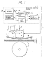
- Fig. 1 is a schematic view showing a melt-type thermal transfer printing apparatus in accordance with the first embodiment of the present invention.
- a melt-type thermal transfer printing sheet 2 (hereinafter referred to as printing sheet 2) serves as a recording medium.
- An ink ribbon 3 is brought into contact with the printing sheet 2.
- a thermal head 4 is provided to press the ink ribbon 3. Both of printing sheet 2 and ink ribbon 3 are sandwiched between the thermal head 4 and a platen roller 5.
- the platen roller 5 rotates to convey the printing sheet 2.
- a pressing device 7 generates a predetermined force for pressing the thermal head 4.
- a gradation control circuit 10 controls an electric power supplied to the thermal head 4 to vary a melt or fusion area of ink 3a so as to obtain a multi-gradational image on the printing sheet 2.
- Ink ribbon 3 comprises hot melt or heat fusible ink 3a coated on a polyester (PET) thin film 3b.
- PET polyester
- the hot melt ink 3a is faced down when pressed by the thermal head 4 so that the hot melt ink 3a is directly brought into contact with the surface of the printing sheet 2.
- Thermal head 4 comprises a plurality of heater elements 8, ----, 8 arranged in line. These heater elements 8, ---, 8 are incorporated or housed in a head case 9.
- Gradation control circuit 10 comprises a memory 11, a comparator 12, a heat timer 13, a pulse generator 14, and a gradation number generator 15.
- the memory 11 memorizes image data (D N ) representing gradation numbers corresponding to images to be printed.
- the comparator 12 compares each of image data (D 0 , D 1 , ---, D n ) of respective gradation levels generated from the memory 11 with a gradation number (V D ) produced from the gradation number generator 15.
- the heat timer 13 sets a heat time in accordance with each gradation.
- the pulse generator 14 supplies a pulse signal to the heater element 8 of the thermal head 4 to increase the temperature of heater element 8 based on an output of the comparator 12 and an output of the heat timer 13.
- the comparator 12 As a result of a comparison between the image data (D 0 , D 1 , ----, D n ) and the gradation number (V D ), the comparator 12 generates a signal of 1 when D N ⁇ V D and generates a signal of 0 when D N ⁇ V D .
- Pressing device 7 comprises a plunger 21, a push rod 22 linked with a rod 21a of plunger 21, and a return spring 23 attached to the thermal head 4.
- plunger 21 When plunger 21 is operated, the push rod 22 is rotated or swung about its pivot center to shift the thermal head 4 toward the platen roller 5.
- the printing sheet 2 and the ink ribbon 3 are held or sandwiched together between the thermal head 4 and the platen roller 5.
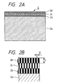
- Figs. 2A and 2B are cross-sectional views showing a melt-type thermal transfer printing sheet in accordance with the first embodiment of the present invention.
- Fig. 2B is an enlarged view of Fig. 2A.
- Printing sheet 2 comprises a base material 2a, a third porous layer 2b formed on the surface of this base material 2a, a second porous layer 2c accumulated on this third porous layer 2b, and a first porous layer 2d accumulated on this second porous layer 2c.
- the base material 2a is chiefly made of pulp.
- Each of the first to third porous layers 2b, 2c and 2d has a pore diameter D equal to or smaller than 25 ⁇ m and has a thickness "t" of 10 ⁇ m.
- Fig. 3 is a front view showing the heater elements 8 of the thermal head 4 in accordance with the first embodiment of the present invention.
- Each heater element 8 comprises a heater resistor 26 and a pair of electrodes 27, 27 connected to opposite ends of the heater resistor 26.
- a heater width B i.e., a width in a line direction
- the heater element 8 can surely press a pore in the porous layer.
- Figs. 4A and 4B are views illustrating the operation of the melt-type thermal transfer printing apparatus 1 in accordance with the first embodiment of the present invention.
- the ink ribbon 3 comprising the hot melt or heat fusible ink 3a coated on the thin film 3b, is placed on the printing sheet 2.
- the ink 3a of ink ribbon 3 is faced down and directly brought into contact with the uppermost (i.e., first) porous layer 2d of the printing sheet 2. Both of the printing sheet 2 and the ink ribbon 3 are held between the thermal head 4 and the platen roller 5.
- the thermal head 4 is shifted in a direction indicated by a void arrow.
- both of the printing sheet 2 and the ink ribbon 3 are pressed by the thermal head 4 shifting toward the platen roller 5.
- Each thickness of porous layers 2b, 2c and 2d is reduced in accordance with a pressing force applied from the thermal head 4, as if these porous layers 2b, 2c and 2d were united.
- Figs. 5A and 5B are views illustrating the condition of ink transferred or permeated to a printing sheet of the first embodiment of the present invention.
- the printing sheet comprises two porous layers containing numerous pores having a pore diameter within 25 ⁇ m.
- a pressing force applied on this printing sheet is variably controlled to change the degree of transferred or permeated ink.
- a pressing force was added to the printing sheet by a degree solely allowing the ink to permeate into the pores of the first (i.e., uppermost) layer indicated by void circles.
- the ink was transferred to the first layer at a limited region corresponding to smaller pores having a pore diameter in a range of 1 to 10 ⁇ m among all the pores whose diameters are limited within 25 ⁇ m.
- the pressing force was increased to a higher level allowing the ink to permeate deeply into the second-layer pores indicated by dotted circles as well as the first-layer pores.
- the ink was transferred to the second layer not only at a region corresponding to the smaller pores having a pore diameter of 1 to 10 ⁇ m but also at another region where the larger first-layer pores having a pore diameter of 11 to 25 ⁇ m are overlapped with the larger second-layer pores having a pore diameter of 11 to 25 ⁇ m.
- Fig. 6 is a front view showing a modification of heater elements of the thermal head in accordance with the first embodiment of the present invention.
- Each heater element 28 comprises a heater resistor 36 and a pair of electrodes 37, 37 connected to opposite ends of the heater resistor 36.
- Two heater widths B1 and B2 of each heater element 28 are respectively wider than the pore diameter D of porous layers 2b, 2c and 2d of the printing sheet 2 shown in Fig. 2B. With this relationship, the heater element 28 can surely press a pore in the porous layer.
- a groove 39 is provided at a center of each heater resistor 36.
- the heater resistor 36 serves as two recording dots for a lower gradation, while the heater resistor 36 serves as a single recording dot for a higher gradation.
- numerous multi-gradational levels can be realized.
- a used printing sheet has a porous layer having a pore diameter equivalent to or smaller than 25 ⁇ m.
- the entire width of each heater resistor 36 is set to 70 ⁇ m and the width B3 of the groove 39 is set to 10 to 20 ⁇ m.
- Fig. 7 is a graph showing the resultant characteristics between the gradation number and the density (i.e., multi-gradational characteristics) obtained from the inventive example 1 and the comparative examples 1 and 2.
- An abscissa represents the gradation number, while an ordinate represents the density (OD).
- the comparative example 1 using a conventional printing sheet made of the synthetic paper formed with a single porous layer having a pore diameter of 1 to 10 ⁇ m, demonstrated a desirable multi-gradational characteristics. A good linearity was obtained in a full range from 0 to 256 gradation levels as indicated by a dotted line. The density at the 256 gradation is 1.7 (OD).
- the linearity and the density difference obtained by the comparative example 1 are taken into consideration for evaluating the characteristics of the inventive example 1 and the comparative example 2.
- the inventive example 1 using a printing sheet of the present invention having a three-layered porous arrangement having a pore diameter within 25 ⁇ m, demonstrated a multi-gradational characteristics comparable with that of the comparative example 1.
- a solid line representing the gradational characteristics of the present invention is steep in gradient compared with the dot line representing the gradational characteristics of the comparative example 1.
- a plain paper has a smaller thermal diffusibility compared with a synthetic paper. This is why the gradient of the solid line becomes steep in the range of 96 to 192.
- the present invention makes it possible to reduce the electric power consumption during a printing operation due to the small thermal diffusibility of the plane paper.
- the inventive example 1 is superior to the comparative example 1.
- the inventive example 1 employs a multilayered porous arrangement. With this arrangement, the inventive example 1 obtains an effect substantially the same as that of the comparative example 1 even though the maximum pore diameter of the porous layer is 25 ⁇ m which is significantly larger than 10 ⁇ m of the comparative example 1. Providing numerous pores is effective to suppress the heat diffusion. Furthermore, the inventive example 1 has the maximum density of 1.7 (OD) equal to that of the comparative example 1.
- Comparative example 2 using a printing sheet comprising a porous layer having a pore diameter within 35 ⁇ m, demonstrated a multi-gradational characteristics inferior to that of the inventive example 1 or comparative example 1. As shown by an alternate long and short dash line, the linearity of the comparative example 2 is acceptable. However, the density of the 256 gradation level is 1.2 (OD) which is fairly low compared with 1.7 (OD) of the inventive example 1 or comparative example 1.
- the comparative example 2 has a porous layer whose maximum pore diameter is 35 ⁇ m, which is significantly large compared with 25 ⁇ m of the comparative example 1. Having a too much large pore diameter is disadvantageous in that the ink cannot be diffused effectively along the surface of each pore. Thus, even if the above-described multilayered porous arrangement is employed, the obtainable maximum density is reduced or limited due to insufficiency in the diffusion of ink in the relatively large pores. Accordingly, it is difficult to realize a satisfactory density difference.
- the inventive example 1 brings excellent printing characteristics equivalent to that of the comparative example 1 and superior to that of the comparative example 2.
- Fig. 8 is a schematic view showing a melt-type thermal transfer printing apparatus in accordance with the second embodiment of the present invention.
- the components already disclosed in the melt-type thermal transfer printing apparatus 1 of the first embodiment are denoted by the same reference numerals and will not be explained in detail.
- a melt-type thermal transfer printing sheet 50 (hereinafter referred to as printing sheet 50) serves as a recording medium.
- An ink ribbon 3 is brought into contact with the printing sheet 50.
- a thermal head 60 is provided to press the ink ribbon 3. Both of printing sheet 50 and ink ribbon 3 are held or sandwiched between the thermal head 60 and a platen roller 5.
- a pressing device 7 generates a predetermined force for pressing the thermal head 60.
- a gradation control circuit 10 controls an electric power supplied to the thermal head 60 to vary a melt or fusion area of ink 3a so as to obtain a multi-gradational printing image on the printing sheet 50.
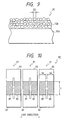
- FIG. 9 is a cross-sectional view showing a melt-type thermal transfer printing sheet in accordance with the second embodiment of the present invention.
- a printing sheet 50 comprises a base material 50a, and a porous layer 50b formed on the surface of this base material 50a.
- the base material 50a is chiefly made of a synthetic paper or pulp.
- the porous layer 50b contains numerous pores having a pore diameter D2 within 25 ⁇ m and accumulated in a multilayered arrangement in the region of porous layer 50b.
- the pores contained in the porous layer 50b are formed simultaneously by the same step without forming each layer independently.
- At least 80% of the pores involved in the porous layer 50b is smaller pores having a pore diameter within 10 ⁇ m and the remainder is larger pores in a range of 10 to 25 ⁇ m.
- the printing sheet 50 comprising the base material 50a and the porous layer 50b, when at least 80% of the pores involved in the porous layer 50b is the smaller pores having a pore diameter within 10 ⁇ m and the remainder is the larger pores in a range of 10 to 25 ⁇ m, makes it possible to obtain a high-quality multi-gradational image and improve the productivity.
- Fig. 10 is a front view showing the heater elements of the thermal head in accordance with the second embodiment of the present invention.
- the thermal head 60 comprises a plurality of heater elements 61,---, 61 arranged in line. These heater elements 61, ---, 61 are incorporated or housed in a head case (not shown).
- Each heater element 61 comprises two split heater resistors 62, 62 and a pair of electrodes 63, 63 each connected to these heater resistors 62, 62.
- a heater width B4, B4 and a length L of each heater resistor 62 are larger than the maximum pore diameter in the porous layer 50B. In this second embodiment, this value needs to be equal to or larger than 25 ⁇ m.
- FIG. 11 is a cross-sectional view showing another melt-type thermal transfer printing sheet in accordance with the second embodiment of the present invention.
- a melt-type thermal transfer printing sheet 70 (hereinafter referred to as printing sheet 70) comprises a base material 70a, and a porous layer 70b formed on the surface of this base material 70a.
- the base material 70a is chiefly made of a synthetic paper or pulp.
- the porous layer 70b contains numerous pores having a pore diameter D3 within 25 ⁇ m and formed into a single layer arrangement simultaneously by the same step.
- At least 80% of the pores of the porous layer 70b is smaller pores having a pore diameter within 10 ⁇ m and the remainder is larger pores in a range of 10 to 25 ⁇ m.
- the printing sheet 70 is excellent in the productivity compared with the above-described printing sheet 50 (refer to Fig. 9) which comprises the multilayered pore arrangement.
- Test conditions for an inventive example 2 is as follows:
- Table 1 shows a distribution of pores in each printing sheet (samples A to F) in accordance with the inventive example 2.
- the printing sheet comprising the base material and the porous layer formed thereon, is photographed by an electronic microscope to measure the distribution of the pores by visual observation.
- Table 2 shows primary characteristics of each printing sheet (samples A to F) in accordance with the inventive example 2.
- Each printing sheet is constituted as follows: Sample A base material ------- synthetic paper layer structure ------- multilayer arrangement main pore diameter distribution 1 to 9 ⁇ m 100 % 25 ⁇ m and above 0%
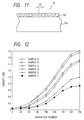
- Fig. 12 is a graph showing characteristics between the gradation number and the density (i.e., multi-gradational characteristics) obtained from the inventive example 2.
- An abscissa represents the gradation number, while an ordinate represents the density (OD).
- Sample A comprising a base material of synthetic paper and a multilayered porous layer comprising numerous pores 100% of which has a pore diameter of 1 to 9 ⁇ m and 0% has a pore diameter exceeding 25 ⁇ m, demonstrated a good linearity in a full range from 0 to 256 gradation levels as well as a higher maximum density reaching 1.8.
- a multi-gradational image having a better S/N and high quality was obtained in an actual printing operation using sample A.
- Sample B comprising a base material of synthetic paper and a porous single layer comprising numerous pores 100% of which has a pore diameter of 1 to 9 ⁇ m and 0% has a pore diameter exceeding 25 ⁇ m, demonstrated a good linearity in a full range from 0 to 256 gradation levels as well as a higher maximum density reaching 1.74.
- the maximum density is slightly lower compared with the sample A. This is believed that a significant influence is given by the single layer construction of the porous layer and by an average pore diameter difference between sample A and sample B.
- a multi-gradational image having a better S/N and high quality was obtained in an actual printing operation using sample B.
- the sample B printing sheet comprising a single porous layer, not only brings an excellent gradation number vs. density characteristics comparable with that of the sample A printing sheet but also has a better productivity leading the multilayer type.
- Sample C comprising a base material of plain paper and a multilayered porous layer comprising numerous pores 91% of which has a pore diameter of 1 to 9 ⁇ m and 0% has a pore diameter exceeding 25 ⁇ m, demonstrated a good linearity in a limited range from 96 to 256 gradation levels as well as a relatively higher maximum density reaching 1.5.
- An actual printing condition of sample C is practically acceptable although the density is slightly low.
- Sample D comprising a base material of plain paper and a multilayered porous layer comprising numerous pores 87% of which has a pore diameter of 1 to 9 ⁇ m and 0% has a pore diameter exceeding 25 ⁇ m, demonstrated a good linearity in a limited range from 96 to 256 gradation levels as well as a relatively higher maximum density reaching 1.45.
- An actual printing condition of sample D is practically acceptable although the density is slightly low.
- the printing sheet can be practically acceptable even if its base material is made of plain paper.
- Sample E comprising a base material of plain paper and a multilayered porous layer comprising numerous pores 33% of which has a pore diameter of 1 to 9 ⁇ m and 5% has a pore diameter exceeding 25 ⁇ m, demonstrated a relatively lower maximum density reaching 1.0.
- An image obtained by sample E was not practically acceptable in its worse S/N, lower density and void-like printing finish.
- Sample F comprising a base material of plain paper and a multilayered porous layer comprising numerous pores 12% of which has a pore diameter of 1 to 9 ⁇ m and 10% has a pore diameter exceeding 25 ⁇ m, demonstrated the lowest maximum density reaching 0.72.
- An image obtained by sample F was not practically acceptable in its worse S/N, lower density and void-like printing finish.
- the printing sheet when at least 80% of the pores in the single or multilayered porous layer formed on a base material is shared by the smaller pores having a pore diameter not exceeding 10 ⁇ m and the remainder is shared by the pores in a range of 10 to 25 ⁇ m, the printing sheet can be practically used and acceptable in the multi-gradational characteristics as well as image quality.
- One aspect of the present invention provides a melt-type thermal transfer printing apparatus using an ink ribbon brought into contact with a recording medium both of which are pressed by a thermal head under a control of an electric power supplied to the thermal head so that a melt or fusion area of ink can be varied to obtain a multi-gradational image on the recording medium.
- the recording medium is a porous surfaced medium including a plurality of porous layers accumulated on a base material. A pore diameter of each porous layer is within 25 ⁇ m.
- the ink ribbon is coated with a hot melt or heat fusible ink. A preferable range of the coating amount of the hot melt or heat fusible ink is a density equal to or smaller than 2.5 g/m 2 .
- the thermal head has a plurality of heater elements arranged in line. Each heater element has a width larger than the pore diameter of the porous layer.
- the present invention makes it possible to realize a high-density multi-gradational printing image comparable with the conventional image realized by using a porous layer having a smaller pore diameter. Accordingly, the multi-gradational image recording can be easily realized by using melt-type ink and a printing sheet comprising plain paper as a base material.
- the above melt-type thermal transfer printing apparatus further comprises a gradation control circuit.
- a memory means memorizes image data representing gradation numbers corresponding to images to be printed.
- a comparing means compares image data of respective gradation levels generated from the memory means with a gradation number produced from a gradation number generating means.
- a heat time setting means sets a heat time in accordance with each gradation.
- a pulse generating means supplies a pulse signal to the heater element of the thermal head to increase the temperature of the heater element based on an output of the comparing means and an output of the heat time setting means.
- melt-type thermal transfer printing apparatus further comprises a pressing means for pressing the thermal head by a predetermined pressure.
- a pressing means for pressing the thermal head by a predetermined pressure.
- a second aspect of the present invention provides a melt-type thermal transfer printing sheet comprising a base material, and a plurality of porous layers formed on this base material, each porous layer having a pore size within 25 ⁇ m. This arrangement makes it possible to realize a high-density multi-gradational image.
- the present invention makes it possible to realize a multi-gradational printing image of high density comparable with the conventional image realized by using a porous layer having a smaller pore diameter.
- This arrangement is advantageous in that a manufacturing cost for a recording medium can be reduced, since a paper having a large pore diameter can be used as the recording medium. Accordingly, a plain paper can be used as a base material.
- a third aspect of the present invention provides a melt-type thermal transfer printing apparatus using an ink ribbon brought into contact with a recording medium both of which are pressed by a thermal head under a control of an electric power supplied to the thermal head so that a melt or fusion area of ink can be varied to realize a multi-gradational image on the recording medium.
- the recording medium is a porous surfaced medium including a single or multilayered porous layer accumulated on a base material.
- the porous layer contains numerous pores at least 80 % of which is smaller pores having a pore diameter within 10 ⁇ m and the remainder is larger pores having diameters in a range of 10 ⁇ m to 25 ⁇ m.
- the ink ribbon is coated with a hot melt or heat fusible ink, preferably, by a density equal to or smaller than 2.5 g/m 2 .
- the present invention makes it possible to realize a multi-gradational printing image of high density comparable with the conventionally image realized by using a porous layer having a smaller pore diameter.
- This arrangement is advantageous in that a manufacturing cost for a recording medium can be reduced compared with that in the prior art, since a paper having a large pore diameter can be used as the recording medium.
- a fourth aspect of the present invention provides a melt-type thermal transfer printing sheet comprising a base material, and a porous layer formed on the base material.
- the porous layer contains numerous pores, at least 80% percentage of which is smaller pores having a pore diameter within 10 ⁇ m and the remainder is larger pores having diameters in a range of 10 ⁇ m to 25 ⁇ m.
- a fifth aspect of the present invention provides a melt-type thermal transfer printing sheet comprising a base material, and a multilayered porous layer formed on the base material.
- the porous layer contains numerous pores, at least 80% percentage of which is smaller pores having a pore diameter within 10 ⁇ m and the remainder is larger pores having a pore diameter in a range of 10 ⁇ m to 25 ⁇ m.
Landscapes
- Physics & Mathematics (AREA)
- Optics & Photonics (AREA)
- Thermal Transfer Or Thermal Recording In General (AREA)
- Electronic Switches (AREA)
Claims (4)
- Schmelzthermotransferdrucksystem, aufweisend:ein Farbband (3), das einen dünnen Film enthält, der mit einer 2,5 g/m2 nicht übersteigenden Dichte mit einer thermoplastischen oder heißschmelzenden Farbe (3a) beschichtet ist,ein Aufzeichnungsmedium (50) mit poröser Oberfläche, das eine poröse Schicht (50b) enthält, die auf einem hauptsächlich aus synthetischem Papier oder Zellstoff hergestellten Basismaterial (50a) geschaffen ist,einen Thermokopf (60) mit mehreren Heizelementen (61), die in einer Linie angeordnet sind,ein Druckmittel (7), um zu veranlassen, daß der Thermokopf einen vorbestimmten Druck auf den dünnen Film des Farbbandes ausübt, wodurch die Farbe des Farbbandes mit den in der porösen Schicht des Aufzeichnungsmediums enthaltenen Poren kräftig in Kontakt gebracht wird, undein Abstufungssteuermittel (10) zum Steuern der elektrischen Leistung, die dem Thermokopf zugeführt wird, um einen Schmelz- oder schmelzbaren Bereich der Farbe des Farbbandes zu variieren, wodurch eine Abbildung mit mehreren Abstufungen auf dem Aufzeichnungsmedium realisiert wird;wobei die poröse Schicht eine mehrlagige poröse Schicht (50b) ist, die erste und zweite Poren enthält, wobei die ersten Poren einen Porendurchmesser in einem Bereich von etwa 1 µm bis etwa 10 µm aufweisen und die zweiten Poren einen Porendurchmesser in einem Bereich von etwa 10 µm bis etwa 25 µm haben, wobei alle in der mehrlagigen porösen Schicht enthaltenen Poren im Porendurchmesser ungefähr 25 µm nicht übersteigen, der Prozentanteil der ersten Poren mindestens 80% und weniger als 100% beträgt und der Prozentanteil der zweiten Poren im wesentlichen größer als 0% ist; undjedes Heizelement (61) der thermischen Heizvorrichtung (60) eine größere Breite als etwa 25 µm aufweist.
- Schmelzthermotransferdrucksystem nach Anspruch 1, dadurch gekennzeichnet, daß
das Abstufungssteuermittel (10) eine Abstufungssteuerschaltung ist, welche aufweist:ein Speichermittel (11), um Bilddaten zu speichern, die Abstufungszahlen entsprechend zu druckenden Bildern repräsentieren;ein Vergleichsmittel (12) zum Vergleichen von Bilddaten jeweiliger Abstufungspegel, die von dem Speichermittel erzeugt werden, mit einer Abstufungszahl jeder Abstufung;ein Heizzeit-Einstellmittel (13) zum Einstellen einer Heizzeit gemäß jeder Abstufung; undein Pulserzeugungsmittel (14) zum Liefern eines Pulssignals an die Heizelemente des Thermokopfes, um die Temperatur der Heizelemente auf der Basis einer Ausgabe des Vergleichsmittels und einer Ausgabe des Heizzeit-Einstellmittels zu erhöhen. - Druckblatt für ein Schmelzthermodrucksystem, mit:einem hauptsächlich aus synthetischem Papier oder Zellstoff hergestellten Basismaterial (50a); undeiner auf dem Basismaterial ausgebildeten porösen Schicht (50b) ;wobei die poröse Schicht eine mehrlagige poröse Schicht (50b) ist, die erste und zweite Poren enthält, wobei die ersten Poren einen Porendurchmesser in einem Bereich von etwa 1 µm bis etwas 10 µm aufweisen und die zweiten Poren einen Porendurchmesser in einem Bereich von etwa 10 µm bis etwa 25 µm haben, wobei alle in der mehrlagigen porösen Schicht enthaltenen Poren im Porendurchmesser etwa 25 µm nicht übersteigen, der Prozentanteil der ersten Poren mindestens 80% und weniger als 100% beträgt und der Prozentanteil der zweiten Poren im wesentlichen größer als 0% ist.
- Druckblatt für ein Schmelzthermodrucksystem, wobei das Schmelzthermotransferdrucksystem umfaßt:ein Farbband (3), das einen dünnen Film enthält, der mit einer 2,5 g/m2 nicht übersteigenden Dichte mit einer thermoplastischen oder heißschmelzenden Farbe beschichtet ist;einen Thermokopf (60) mit mehreren Heizelementen (61), die in einer Linie angeordnet sind, wobei jedes Heizelement eine größere Breite als etwa 25 µm aufweist;ein Druckmittel (7), um zu veranlassen, daß der Thermokopf auf den dünnen Film des Farbbandes einen vorbestimmten Druck ausübt, wodurch die Farbe des Farbbandes mit den in der porösen Schicht des Aufzeichnungsmediums enthaltenen Poren kräftig in Kontakt gebracht wird; undein Abstufungssteuermittel (10) zum Steuern der elektrischen Leistung, die dem Thermokopf zugeführt wird, um einen Schmelz- oder schmelzbaren Bereich der Farbe des Farbbandes zu variieren, wodurch eine Abbildung mit mehreren Abstufungen auf dem Aufzeichnungsmedium realisiert wird; undwobei das Druckblatt umfaßt:ein hauptsächlich aus synthetischem Papier oder Zellstoff hergestelltes Basismaterial (50a); undeine mehrlagige poröse Schicht, die auf dem Basismaterial ausgebildet ist, wobei die mehrlagige poröse Schicht erste und zweite Poren enthält, die ersten Poren einen Porendurchmesser von in einem Bereich von etwa 1 µm bis etwa 10 µm haben und die zweiten Poren einen Durchmesser in einem Bereich von etwa 10 µm bis etwa 25 µm haben, wobei alle in der mehrlagigen porösen Schicht enthaltenen Poren im Porendurchmesser etwa 25 µm nicht übersteigen, der Prozentanteil der ersten Poren mindestens 80% und weniger als 100% beträgt und der Prozentanteil der zweiten Poren im wesentlichen größer als 0% ist.
Applications Claiming Priority (6)
| Application Number | Priority Date | Filing Date | Title |
|---|---|---|---|
| JP20102896 | 1996-07-12 | ||
| JP201028/96 | 1996-07-12 | ||
| JP20102896 | 1996-07-12 | ||
| JP6520997 | 1997-03-18 | ||
| JP6520997A JPH1076693A (ja) | 1996-07-12 | 1997-03-18 | 溶融型熱転写印刷装置及びその印刷用紙 |
| JP65209/97 | 1997-03-18 |
Publications (3)
| Publication Number | Publication Date |
|---|---|
| EP0818319A2 EP0818319A2 (de) | 1998-01-14 |
| EP0818319A3 EP0818319A3 (de) | 1998-01-28 |
| EP0818319B1 true EP0818319B1 (de) | 2001-11-07 |
Family
ID=26406338
Family Applications (1)
| Application Number | Title | Priority Date | Filing Date |
|---|---|---|---|
| EP19970111842 Expired - Lifetime EP0818319B1 (de) | 1996-07-12 | 1997-07-11 | Schmelzwärmetransferdruckgerät und Druckschicht dafür |
Country Status (4)
| Country | Link |
|---|---|
| US (1) | US5897254A (de) |
| EP (1) | EP0818319B1 (de) |
| JP (1) | JPH1076693A (de) |
| DE (1) | DE69707982T2 (de) |
Families Citing this family (12)
| Publication number | Priority date | Publication date | Assignee | Title |
|---|---|---|---|---|
| US6161971A (en) * | 1997-11-14 | 2000-12-19 | Asahi Kogaku Kogyo Kabushiki Kaisha | Image-forming system |
| JPH11268313A (ja) * | 1998-03-25 | 1999-10-05 | Alps Electric Co Ltd | 熱転写プリンタ |
| EP1493593B1 (de) | 2000-02-01 | 2006-05-31 | Polaroid Corporation | Thermisches Übertragungsaufzeichnungsverfahren mit einer amorphen Farbstoffphase |
| US6537410B2 (en) | 2000-02-01 | 2003-03-25 | Polaroid Corporation | Thermal transfer recording system |
| US6572951B2 (en) | 2000-03-31 | 2003-06-03 | Nippon Paper Industries Co., Ltd. | Printing sheet |
| US6999202B2 (en) | 2001-03-27 | 2006-02-14 | Polaroid Corporation | Method for generating a halftone of a source image |
| WO2002096659A1 (en) | 2001-05-30 | 2002-12-05 | Polaroid Corporation | Thermal mass transfer imaging system |
| US6937365B2 (en) | 2001-05-30 | 2005-08-30 | Polaroid Corporation | Rendering images utilizing adaptive error diffusion |
| ATE303901T1 (de) * | 2001-05-30 | 2005-09-15 | Polaroid Corp | Hochgeschwindigkeitsphotodruckgerät |
| US6842186B2 (en) * | 2001-05-30 | 2005-01-11 | Polaroid Corporation | High speed photo-printing apparatus |
| US6906736B2 (en) * | 2002-02-19 | 2005-06-14 | Polaroid Corporation | Technique for printing a color image |
| US8773685B2 (en) | 2003-07-01 | 2014-07-08 | Intellectual Ventures I Llc | High-speed digital image printing system |
Family Cites Families (17)
| Publication number | Priority date | Publication date | Assignee | Title |
|---|---|---|---|---|
| JPS58110287A (ja) * | 1981-12-24 | 1983-06-30 | Mitsubishi Paper Mills Ltd | 記録用シ−ト |
| JPH0197686A (ja) * | 1987-10-08 | 1989-04-17 | Ricoh Co Ltd | 感熱転写記録媒体 |
| EP0334607A3 (de) * | 1988-03-23 | 1991-03-13 | Fuji Photo Film Co., Ltd. | Wärmeempfindliches Aufzeichnungsschichtmaterial |
| US5275867A (en) * | 1991-02-19 | 1994-01-04 | Asahi Glass Company Ltd. | Recording film and recording method |
| EP0537485B1 (de) * | 1991-10-04 | 1996-11-13 | Minnesota Mining And Manufacturing Company | Neue Rezeptoren für Farbstoffübertragung |
| JP2855925B2 (ja) * | 1991-12-06 | 1999-02-10 | 王子製紙株式会社 | サーマル画像プリントシート |
| JP2850930B2 (ja) * | 1992-10-12 | 1999-01-27 | 日本ビクター株式会社 | 溶融型熱転写プリントシステム |
| US5654080A (en) * | 1992-10-13 | 1997-08-05 | Dai Nippon Printing Co., Ltd. | Thermal transfer medium |
| GB9306073D0 (en) * | 1993-03-24 | 1993-05-12 | Ici Plc | Thermal transfer printing receiver sheet |
| US5441921A (en) * | 1993-06-21 | 1995-08-15 | Agfa-Gevaert, N.V. | Image receiving element for thermal dye diffusion transfer |
| JP2891054B2 (ja) * | 1993-08-23 | 1999-05-17 | 日本ビクター株式会社 | 溶融型熱転写プリントシステム |
| EP0800930B1 (de) * | 1993-10-08 | 2000-09-20 | Dai Nippon Printing Co., Ltd. | Wärmeübertragungsbild aufnehmendes Blatt |
| JPH07125468A (ja) * | 1993-11-04 | 1995-05-16 | Victor Co Of Japan Ltd | 熱転写記録用紙及びこれを用いる熱転写印刷装置 |
| JPH0834169A (ja) * | 1994-07-25 | 1996-02-06 | Mitsubishi Paper Mills Ltd | 感熱転写用受像シート |
| JPH08132747A (ja) * | 1994-11-04 | 1996-05-28 | Dainippon Printing Co Ltd | 熱転写受像シートおよびその光沢制御方法 |
| GB9425874D0 (en) * | 1994-12-21 | 1995-02-22 | Ici Plc | Receiver sheet |
| US5631076A (en) * | 1995-02-24 | 1997-05-20 | New Oji Paper Co., Ltd. | Hot melt ink thermal transfer recording sheet |
-
1997
- 1997-03-18 JP JP6520997A patent/JPH1076693A/ja active Pending
- 1997-07-11 US US08/893,763 patent/US5897254A/en not_active Expired - Lifetime
- 1997-07-11 EP EP19970111842 patent/EP0818319B1/de not_active Expired - Lifetime
- 1997-07-11 DE DE69707982T patent/DE69707982T2/de not_active Expired - Lifetime
Also Published As
| Publication number | Publication date |
|---|---|
| DE69707982T2 (de) | 2002-06-20 |
| EP0818319A3 (de) | 1998-01-28 |
| DE69707982D1 (de) | 2001-12-13 |
| JPH1076693A (ja) | 1998-03-24 |
| EP0818319A2 (de) | 1998-01-14 |
| US5897254A (en) | 1999-04-27 |
Similar Documents
| Publication | Publication Date | Title |
|---|---|---|
| US5897254A (en) | Melt-type thermal transfer printing apparatus and a printing sheet with multiple porous layers | |
| US6585366B2 (en) | Image forming method | |
| EP0348157B1 (de) | Trägerschicht für eine wärmeempfindliche Bildübertragungsempfangsschicht und Verfahren zu deren Herstellung | |
| JP2850930B2 (ja) | 溶融型熱転写プリントシステム | |
| US5384585A (en) | Thermal stenciling device | |
| EP0496612A1 (de) | Wärmeempfindliche Druckschablone | |
| US8264511B2 (en) | Printing apparatus and thermal transfer printing method | |
| EP0500333B1 (de) | Thermische Druckschablone und Verfahren zu deren Herstellung | |
| EP0479225A1 (de) | Thermisches Übertragungsdruckverfahren und Druckmaterialien, die bei diesem Verfahren verwendet werden | |
| EP0409598B1 (de) | Thermische Farbbildübertragungsempfangsschicht | |
| US5592209A (en) | Device and method for dot-matrix thermal recording | |
| EP0500334A2 (de) | Punktmatrixdrucker für wärmeempfindliche Aufzeichnung | |
| GB2258843A (en) | An image forming method using a thermal transfer. | |
| DE68920410T2 (de) | Thermo-Drucker und Faksimilevorrichtung. | |
| EP2067625A2 (de) | Druckervorrichtung und Laminierverfahren | |
| US5561451A (en) | Sublimation type printer and photographic paper therefor | |
| US6211893B1 (en) | Multi-gradation recording method | |
| US5825394A (en) | Thermal print head calibration and operation method for fixed imaging elements | |
| JP3656891B2 (ja) | サーマルヘッド | |
| US4651167A (en) | Printing method | |
| JP2004299377A (ja) | 転写用加圧ロール、転写装置及びインクジェット記録装置 | |
| US6460454B1 (en) | System for making heat-sensitive stencil master | |
| JP4209371B2 (ja) | 画像形成方法および画像形成装置 | |
| EP0788886B1 (de) | Thermischer Übertragungsdrucker und thermisches Übertragungsdruckverfahren unter Verwendung desselben | |
| US20040218917A1 (en) | Transfer pressure roll, transfer device and image recording apparatus |
Legal Events
| Date | Code | Title | Description |
|---|---|---|---|
| PUAI | Public reference made under article 153(3) epc to a published international application that has entered the european phase |
Free format text: ORIGINAL CODE: 0009012 |
|
| PUAL | Search report despatched |
Free format text: ORIGINAL CODE: 0009013 |
|
| AK | Designated contracting states |
Kind code of ref document: A2 Designated state(s): AT BE CH DE DK ES FI FR GB GR IE IT LI LU MC NL PT SE |
|
| AK | Designated contracting states |
Kind code of ref document: A3 Designated state(s): AT BE CH DE DK ES FI FR GB GR IE IT LI LU MC NL PT SE |
|
| 17P | Request for examination filed |
Effective date: 19980313 |
|
| RBV | Designated contracting states (corrected) |
Designated state(s): DE FR GB |
|
| 17Q | First examination report despatched |
Effective date: 19981229 |
|
| GRAG | Despatch of communication of intention to grant |
Free format text: ORIGINAL CODE: EPIDOS AGRA |
|
| GRAG | Despatch of communication of intention to grant |
Free format text: ORIGINAL CODE: EPIDOS AGRA |
|
| GRAH | Despatch of communication of intention to grant a patent |
Free format text: ORIGINAL CODE: EPIDOS IGRA |
|
| GRAH | Despatch of communication of intention to grant a patent |
Free format text: ORIGINAL CODE: EPIDOS IGRA |
|
| GRAA | (expected) grant |
Free format text: ORIGINAL CODE: 0009210 |
|
| AK | Designated contracting states |
Kind code of ref document: B1 Designated state(s): DE FR GB |
|
| REF | Corresponds to: |
Ref document number: 69707982 Country of ref document: DE Date of ref document: 20011213 |
|
| REG | Reference to a national code |
Ref country code: GB Ref legal event code: IF02 |
|
| ET | Fr: translation filed | ||
| PLBE | No opposition filed within time limit |
Free format text: ORIGINAL CODE: 0009261 |
|
| STAA | Information on the status of an ep patent application or granted ep patent |
Free format text: STATUS: NO OPPOSITION FILED WITHIN TIME LIMIT |
|
| 26N | No opposition filed | ||
| REG | Reference to a national code |
Ref country code: DE Ref legal event code: R082 Ref document number: 69707982 Country of ref document: DE Representative=s name: MANITZ, FINSTERWALD & PARTNER GBR, DE |
|
| REG | Reference to a national code |
Ref country code: DE Ref legal event code: R082 Ref document number: 69707982 Country of ref document: DE Representative=s name: MANITZ, FINSTERWALD & PARTNER GBR, DE Effective date: 20120430 Ref country code: DE Ref legal event code: R081 Ref document number: 69707982 Country of ref document: DE Owner name: JVC KENWOOD CORPORATION, JP Free format text: FORMER OWNER: VICTOR COMPANY OF JAPAN, LTD., YOKOHAMA, JP Effective date: 20120430 |
|
| REG | Reference to a national code |
Ref country code: FR Ref legal event code: TP Owner name: JVC KENWOOD CORPORATION, JP Effective date: 20120705 |
|
| PGFP | Annual fee paid to national office [announced via postgrant information from national office to epo] |
Ref country code: GB Payment date: 20120711 Year of fee payment: 16 |
|
| PGFP | Annual fee paid to national office [announced via postgrant information from national office to epo] |
Ref country code: FR Payment date: 20120719 Year of fee payment: 16 Ref country code: DE Payment date: 20120704 Year of fee payment: 16 |
|
| GBPC | Gb: european patent ceased through non-payment of renewal fee |
Effective date: 20130711 |
|
| REG | Reference to a national code |
Ref country code: FR Ref legal event code: ST Effective date: 20140331 |
|
| PG25 | Lapsed in a contracting state [announced via postgrant information from national office to epo] |
Ref country code: DE Free format text: LAPSE BECAUSE OF NON-PAYMENT OF DUE FEES Effective date: 20140201 Ref country code: GB Free format text: LAPSE BECAUSE OF NON-PAYMENT OF DUE FEES Effective date: 20130711 |
|
| REG | Reference to a national code |
Ref country code: DE Ref legal event code: R119 Ref document number: 69707982 Country of ref document: DE Effective date: 20140201 |
|
| PG25 | Lapsed in a contracting state [announced via postgrant information from national office to epo] |
Ref country code: FR Free format text: LAPSE BECAUSE OF NON-PAYMENT OF DUE FEES Effective date: 20130731 |