EP0818320A2 - Appareil d'enregistrement - Google Patents
Appareil d'enregistrement Download PDFInfo
- Publication number
- EP0818320A2 EP0818320A2 EP97111765A EP97111765A EP0818320A2 EP 0818320 A2 EP0818320 A2 EP 0818320A2 EP 97111765 A EP97111765 A EP 97111765A EP 97111765 A EP97111765 A EP 97111765A EP 0818320 A2 EP0818320 A2 EP 0818320A2
- Authority
- EP
- European Patent Office
- Prior art keywords
- convey
- recording
- recording sheet
- roller
- discharge
- Prior art date
- Legal status (The legal status is an assumption and is not a legal conclusion. Google has not performed a legal analysis and makes no representation as to the accuracy of the status listed.)
- Granted
Links
Images





Classifications
-
- B—PERFORMING OPERATIONS; TRANSPORTING
- B41—PRINTING; LINING MACHINES; TYPEWRITERS; STAMPS
- B41J—TYPEWRITERS; SELECTIVE PRINTING MECHANISMS, i.e. MECHANISMS PRINTING OTHERWISE THAN FROM A FORME; CORRECTION OF TYPOGRAPHICAL ERRORS
- B41J13/00—Devices or arrangements of selective printing mechanisms, e.g. ink-jet printers or thermal printers, specially adapted for supporting or handling copy material in short lengths, e.g. sheets
- B41J13/10—Sheet holders, retainers, movable guides, or stationary guides
-
- B—PERFORMING OPERATIONS; TRANSPORTING
- B41—PRINTING; LINING MACHINES; TYPEWRITERS; STAMPS
- B41J—TYPEWRITERS; SELECTIVE PRINTING MECHANISMS, i.e. MECHANISMS PRINTING OTHERWISE THAN FROM A FORME; CORRECTION OF TYPOGRAPHICAL ERRORS
- B41J13/00—Devices or arrangements of selective printing mechanisms, e.g. ink-jet printers or thermal printers, specially adapted for supporting or handling copy material in short lengths, e.g. sheets
- B41J13/0009—Devices or arrangements of selective printing mechanisms, e.g. ink-jet printers or thermal printers, specially adapted for supporting or handling copy material in short lengths, e.g. sheets control of the transport of the copy material
- B41J13/0027—Devices or arrangements of selective printing mechanisms, e.g. ink-jet printers or thermal printers, specially adapted for supporting or handling copy material in short lengths, e.g. sheets control of the transport of the copy material in the printing section of automatic paper handling systems
Definitions
- the present invention relates to a recording apparatus such as a printer, a copying machine, a word processor, a personal computer, a facsimile and the like. More particularly, it relates to a recording apparatus in which a recording sheet is pinched between and conveyed by a pinch roller and a convey roller and, after recording, the recording sheet is pinched between and discharged by a discharge roller and spur wheels.
- a pinch roller 5 is always urged against a recording sheet 3 or a convey roller 4. Further, a discharge roller 11 is selected to have a convey amount slightly greater than that of the convey roller 4 so that tension is applied to the recording sheet 3 to eliminate looseness of the recording sheet and permit the recording under a good condition. After the recording sheet 3 leaves the pinch roller 5, the recording sheet is discharged mainly by a conveying force of the discharge roller 11.
- the present invention provides a (first) recording apparatus comprising a recording portion for effecting the recording on a recording sheet, a convey means for conveying the recording sheet to the recording portion by pinching the recording sheet between a pinch roller and a convey roller, and a discharge means for discharging the recording sheet by pinching the recording sheet between a spur wheel and a discharge roller.
- It further comprises an urging means for urging the pinch roller against the recording sheet, an urging force controlling means for controlling an urging force of the urging means, and a detecting means for detecting the fact that a trail end of the recording sheet is conveyed up to a predetermined position disposed upstream of a position where the trail end of the recording sheet leaves the pinch roller, wherein the urging force controlling means reduces the urging force of the urging means on the basis of a detection result from the detecting means.
- the present invention further provides a recording apparatus comprising a (second) recording portion for effecting the recording on a recording sheet, a convey means for conveying the recording sheet to the recording portion by pinching the recording sheet between a pinch roller and a convey roller, and a discharge means for discharging the recording sheet by pinching the recording sheet between a spur wheel and discharge roller.
- It further comprises an urging means for urging the pinch roller against the recording sheet, an urging force controlling means for controlling an urging force of the urging means, and a detecting means for detecting the fact that a trail end of the recording sheet is conveyed up to a predetermined position disposed upstream of a position where the trail end of the recording sheet leaves the pinch roller, wherein the urging force controlling means releases the urging force of the urging means on the basis of a detection result from the detecting means.
- the present invention also provides a (third) recording apparatus comprising a recording portion for effecting the recording on a recording sheet, a convey means for conveying the recording sheet to the recording portion by pinching the recording sheet between a pinch roller and a convey roller, and a discharge means for discharging the recording sheet by pinching the recording sheet between a spur wheel and a discharge roller. It further comprises a rotation controlling means for controlling rotations of the convey roller and the discharge roller, and a detecting means for detecting the fact that a trail end of the recording sheet is conveyed up to a predetermined position disposed upstream of a position where the trail end of the recording sheet leaves the pinch roller, wherein the rotation controlling means reduces convey amounts of the convey roller and the discharge roller corresponding to one line space.
- the present invention further provides a (fourth) recording apparatus comprising a recording portion for effecting the recording on a recording sheet, a convey means for conveying the recording sheet to the recording portion by pinching the recording sheet between a pinch roller and a convey roller, and a discharge means for discharging the recording sheet by pinching the recording sheet between a spur wheel and a discharge roller. It further comprises a rotation controlling means for controlling rotation of the discharge roller, and a detecting means for detecting the fact that a trail end of the recording sheet is conveyed up to a predetermined position disposed upstream of a position where the trail end of the recording sheet leaves the pinch roller, wherein the rotation controlling means reduces a convey amount of the discharge roller corresponding to one line space.
- the first or second recording apparatus may further include a rotation controlling means for controlling rotations of the convey roller and the discharge roller so that the rotation controlling means reduces convey amounts of the convey roller and the discharge roller corresponding to one line space.
- the first or second recording apparatus may further include a rotation controlling means for controlling rotation of the discharge roller so that the rotation controlling means reduces convey amount of the discharge roller corresponding to one line space.
- the rotation controlling means may set the convey amount of the discharge roller to become the same as a convey amount of the convey roller before detected by the detecting means.
- the rotation controlling means may set the convey amount of the discharge roller to become the same as a convey amount of the convey roller before detected by the detecting means.
- the rotation controlling means may set the convey amount of the discharge roller to become the same as a convey amount of the convey roller before detected by the detecting means.
- the rotation controlling means may set the convey amount of the discharge roller to become the same as a convey amount of the coney roller before detected by the detecting means.
- the detection means may comprise a sensor disposed in the vicinity of the convey roller, and a rotation amount measuring means for measuring a rotation amount of the convey roller.
- the recording portion may be of ink jet recording type in which the recording is effected by discharging ink in response to a signal.
- the recording portion may be of ink jet recording type in which the recording is effected by discharging ink by growth of a bubble formed by heating the ink to exceed the film-boiling temperature generated by energizing an electrical/thermal converter in response to a signal.
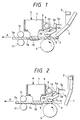
- Figs. 1 to 3 are sectional views (showing a side of a convey path for a recording sheet) for explaining an ink jet recording apparatus according to a first embodiment of the present invention.
- the arrow A indicates a conveying direction for the recording sheet.
- the recording sheet is conveyed from a condition shown in Fig. 1 to a condition shown in Fig. 3.
- a pinch roller 5 is supported by a pinch roller holder 5a which is pivotally mounted on a pinch roller holder shaft 5b and is biased by a compression spring 5c so that the pinch roller is urged against a convey roller 4.
- the convey roller 4 cooperates with the pinch roller 5 to convey the recording sheet toward the conveying direction (shown by the arrow A).
- the convey roller 4 is driven by a convey motor (not shown) to convey the recording sheet 3 by a predetermined amount.
- a stepping motor is used as the convey motor.
- a sheet end detecting PE sensor lever 1 for detecting presence/absence of the recording sheet 3 is disposed upstream of the convey roller 4 and the pinch roller 5 in the recording sheet conveying direction.
- a carriage 8 provided in a recording portion 6 is supported by a guide shaft 9 for reciprocal movement in a direction perpendicular to the conveying direction A for the recording sheet 3. Further, a recording head (recording means) 7 is mounted on the carriage 8 to record on the recording sheet 3 conveyed onto a platen 10 by the convey roller 4 and the pinch roller 5.
- the recording means may be of ink jet recording type in which the recording is effected by discharging ink from the recording head. That is to say, the recording head 7 includes fine liquid discharge openings (orifices), liquid passages, energy acting portions provided in the respective liquid passages, and energy generating means for generating bubble forming energy to be applied to the liquid in the energy acting portions.
- Such energy generating means there are recording systems using electrical/thermal converters such as piezo-electric elements, recording systems using energy generating means in which a liquid droplet is discharged by heating the liquid by means of electromagnetic wave such as laser, recording systems using energy generating means in which liquid is discharged by heating the liquid by means of an electrical/thermal converter such as a heat generating element including a heat generating resistance body, and the like.
- the recording head used in the ink jet recording system among the recording systems since liquid discharge openings (orifices) for discharging recording liquid droplets can be arranged with high density, the recording can be effected with high resolving power. Further, the recording heads using electrical/thermal converters as the energy generating means can easily be made compact, can effectively utilize advantages of IC techniques and/or micro-working techniques in which progress and reliability have been remarkably increased in a recent semi-conductor field, can easily be mounted with high density and can be made cheaper.
- the recording head 7 can be moved so that a distance between a front surface 7a of the recording head and a recording surface 3a of the recording sheet 3 can be maintained properly in correspondence to a thickness of the recording sheet 3.
- Spur wheels 12 are urged against a discharge roller 11 by spring(s) (not shown) to serve as a pinch roller for the discharge roller.
- the spur wheel 12 cooperates with the discharge roller 11 to discharge the recording sheet 3 onto a discharge tray (not shown) without smudging the recording surface 3a of the recording sheet 3.
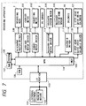
- Fig. 5 is a block diagram showing a control portion of the ink jet recording apparatus.
- An MPU 104 for controlling the entire apparatus has a control time governing timer 105.
- a ROM 106 serves to store control program of the MPU and the like, and a RAM 107 serves as a work area of the MPU 104 and serves to store information such as a speed of the carriage 8 and the like.
- An EEPROM 108 serves to protect the information even after a power source is turned OFF.
- a discharge heater driver 109 serves to drive a discharge heater for causing the recording head to discharge ink in response to recording information, and a carriage motor driver 110 serves to drive a carriage motor 111 for shifting the carriage 8 through a timing belt and pulleys (not shown).
- a convey motor driver 112 serves to control the driving of a convey motor 113 for driving the convey roller 4.
- a PE sensor 2 for detecting the presence/absence of the recording sheet 3 and tip and trail ends of the recording sheet is disposed upstream of the convey roller 4.
- a recovery system motor driver 114 serves to control the driving of a discharge recovery treating apparatus such as an ink suction device (not shown) for restoring the recording head to a record permitting condition or for maintaining the recording head in the record permitting condition.
- a sensor 116 serves to detect an operating position of a cam (not shown) of the discharge recovery treating apparatus.
- a solenoid driver 117 serves to control the driving of a solenoid 19 for controlling the urging of the pinch roller.
- An interface portion 103 connects the recording apparatus to a host computer so that the information can be communicated between the recording apparatus and the host computer through the interface portion.
- An electronic equipment 101 such as a computer, a word processor and the like connected to the recording apparatus through the interface portion 103, and a printer driver 102 serves to set various conditions regarding the recording apparatus and send commands to the recording apparatus in accordance with the set conditions.
- One-line recording is performed on a predetermined position of the recording sheet 3 by the recording apparatus and then the recording sheet 3 is conveyed by an amount corresponding to one line space. Such one-line recording and conveyance of the recording sheet are alternately repeated.
- the recording sheet 3 leaves the PE sensor lever 1, the trail end of the recording sheet is detected.
- the recording sheet 3 is conveyed by a predetermined distance L (Fig. 2) from a position where the PE sensor lever 1 was contacted with the recording sheet 3 to a position where the pinch roller 5 is contacted with the trail end of the recording sheet 3.
- the number of steps corresponding to the distance L is judged by a CPU.
- the predetermined position can be appropriately selected within a range between a separation position where the recording sheet has just left the pinch roller and a position situated upstream of the separation position and spaced apart from the separation position by a distance corresponding to one line space.
- the MPU detects the fact that the trail end of the recording sheet 3 has passed through the PE sensor lever 1, by utilizing the PE sensor 2 and the PE sensor lever 1. After the trail end of the recording sheet 3 was detected by the PE sensor 2, when the stepping motor (convey motor 113) was rotated by the number of steps required for the convey roller to convey the recording sheet 3 by the predetermined distance L, the solenoid 19 is turned ON by the MPU.
- the urging (pressurizing) of the pinch roller 2 is released in order to release the downstream force F acting on the trail end of the recording sheet 3
- the urging force of the pinch roller may be reduced or weakened, in place of complete release of the urging force of the pinch roller.
- the shift amount of the pinch roller 2 obtained by the solenoid 19 and the connection portion 20 may be selected to an amount that the pinch roller does not separate from the upper surface of the recording sheet.
- a driving force from a motor gear 13a is transmitted to a convey roller gear 15 through a two-stage gear 14a and then is transmitted to a discharge roller gear 16 through a two-stage gear 14b.
- a total speed reduction gear ratio from the convey motor to the convey roller gear 15 is selected to 1:15 and a total speed reduction gear ratio from the convey motor to the discharge roller gear 16 is selected to 2:29.
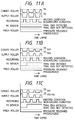
- Fig. 11A shows a relation between time lapse (when the trail end of the recording sheet 3 is situated upstream of the pinch roller 2), and a convey amount condition of the recording sheet 3 by means of the convey roller 4, a convey amount condition of the recording sheet 3 by means of the discharge roller 11, a recording condition of the recording head, a detection condition of the PE sensor and a pressurizing condition of the pinch roller.
- a convey amount Vb of the discharge roller is selected to become greater than a convey amount Va of the convey roller by 2 to 3%, so that the recording sheet 3 can be conveyed without looseness.
- the recording operation is performed while the recording sheet 3 is not being conveyed.
- the PE sensor is in a condition that it does not detect the trail end of the recording sheet and the pinch roller is in the pressurizing condition.
- the trail end of the recording sheet 3 is detected when the recording sheet 3 leaves the PE sensor lever 1, and the recording sheet 3 is conveyed by the predetermined distance L.
- the convey amount corresponding to one line space which was previously set is changed to a new amount.
- a convey amount of 48 steps per one line space is set in the convey motor 112, and, thereafter, the convey amount is changed to 47 steps per one line space.
- Such a driving condition is shown in Fig. 11B.
- the convey amount of the convey motor 113 corresponding to one line space is changed, the convey amount of the convey roller 4 is changed or reduced from Va to Va1 and the convey amount of the discharge roller 11 is changed or reduced from Vb to Vb1.
- the changed convey amount Vb1 of the discharge roller 11 is not limited to a specific value but may be determined in accordance with material of the recording sheet 3 and/or discharging ability of the discharge roller 11.
- An example that the changed convey amount of the discharge roller is set to be equal to the convey amount of the convey roller 4 before the trail end of the recording sheet 3 is detected by the PE sensor 2 is shown in Fig. 11C.
- the recording sheet 3 is conveyed without changing the convey distance per one line space between before and after the trail end of the recording sheet 3 is detected by the PE sensor 2. With this arrangement, the convey accuracy of the trail end of the recording sheet can be improved.
- the predetermined position can be appropriately selected within the range between the separation position where the recording sheet has just left the pinch roller and the position situated upstream of the separation position and spaced apart from the separation position by the distance corresponding to one line space, the predetermined position may be situated upstream of such a range.
- a driving force of the convey roller 4 is transmitted from a motor gear 13a to a convey roller gear 15 through a two-stage gear 14a and a driving force of the discharge roller 11 is transmitted from a motor gear 13b to a discharge roller gear 16 through a two-stage gear 14b.
- a total speed reduction gear ratio from the convey motor to the convey roller gear 15 is selected to 1:15 and a total speed reduction gear ratio from the discharge motor to the discharge roller gear 16 is selected to 2:29.
- Fig. 6 is a block diagram showing a control portion of an ink jet recording apparatus according to this embodiment.
- a convey motor driver 118 for controlling the driving of the discharge motor 119 for driving the discharge roller 11 is added, in comparison with the control portion shown in Fig. 5.
- the trail end of the recording sheet 3 is detected when the recording sheet 3 leaves the PE sensor lever 1, and the recording sheet 3 is conveyed by the predetermined distance L. Now, the convey amount corresponding to one line space which was previously set is changed from Vb to Vb1 smaller than Vb.
- Fig. 11F shows a driving condition in this case.
- the changed convey amount Vb1 of the discharge roller 11 is not limited to a specific value but may be determined in accordance with material of the recording sheet 3 and/or discharging ability of the discharge roller 11.
- An example that the changed convey amount of the discharge roller is set to be equal to the convey amount of the convey roller 4 before the trail end of the recording sheet 3 is detected by the PE sensor 2 is shown in Fig. 12A.
- the recording sheet 3 is conveyed without changing the convey distance per one line space between before and after the trail end of the recording sheet 3 is detected by the PE sensor 2. With this arrangement, the convey accuracy of the trail end of the recording sheet can be improved.
- the third embodiment can be combined with the first embodiment.
- driving conditions shown in Figs. 12B and 12C are used.
- the increase in the convey distance of the recording sheet due to the downstream force F of the pinch roller 5 acting on the trail end of the recording sheet 3 can be prevented.
- the predetermined position can be appropriately selected within the range between the separation position where the recording sheet has just left the pinch roller and the position situated upstream of the separation position and spaced apart from the separation position by the distance corresponding to one line space, the predetermined position may be situated upstream of such a range.
- Fig. 10 is an explanatory view showing a concrete arrangement of a drive system in which a convey roller and a discharge roller are driven by a common drive source and a clutch gear is interposed between a convey roller 4 and a discharge roller 11.
- a driving force from a motor gear 13a is transmitted to a convey roller gear 15 through a two-stage gear 14a and then is transmitted to a discharge roller gear 16 through a two-stage gear 14b.
- the two-stage gear 14b is rotatably supported by a two-stage gear guide 18a and a two-stage gear guide shaft 18b so that the two-stage gear can be shifted upwardly by a solenoid (not shown).
- a clutch gear 17a has an input associated with the convey roller gear 15 and an output associated with the discharge roller gear 16.
- a total speed reduction gear ratio from the convey motor to the convey roller gear 15 is selected to 1:15 and a total speed reduction gear ratio from the discharge motor to the discharge roller gear 16 is selected to 2:29.
- Fig. 7 is a block diagram showing a control portion of an ink jet recording apparatus according to this embodiment.
- a two-stage gear guide drive solenoid driver 120 for driving a two-stage gear guide drive solenoid 121 is added, in comparison with the control portion shown in Fig. 5.
- the trail end of the recording sheet 3 is detected when the recording sheet 3 leaves the PE sensor lever 1, and the recording sheet 3 is conveyed by the predetermined distance L.
- the two-stage gear 14b is shifted upwardly to disconnect the discharge roller gear 16 from the convey roller gear 15.
- the driving force is transmitted to the convey roller gear 15 through the two-stage gear 14a and then is transmitted to the discharge roller gear 16 through the input and the output of the clutch gear 17a. Since the speed reduction ratio from the convey motor to the convey roller gear 15 is 1:15 and the speed reduction ratio from the convey motor to the discharge roller gear 16 also becomes 1:15, the convey amount of the discharge roller 11 becomes the same as that of the convey roller 4.
- Fig. 12A shows a driving condition in this case.
- the fourth embodiment can be combined with the first embodiment.
- a driving condition shown in Fig. 12C is used.
- the increase in the convey distance of the recording sheet due to the downstream force F of the pinch roller 5 acting on the trail end of the recording sheet 3 can be prevented.
- the predetermined position can be appropriately selected within the range between the separation position where the recording sheet has just left the pinch roller and the position situated upstream of the separation position and spaced apart from the separation position by the distance corresponding to one line space, the predetermined position may be situated upstream of such a range.
- the values set in the above-mentioned various embodiments are not limited to the aforementioned ones but may be appropriately selected.
- the recording means of the recording apparatus is not limited to the ink jet recording system but may be of other recording type.
- the present invention relates to the recording apparatus in which the recording sheet is conveyed to the recording portion by a pinch roller and a convey roller while being pinched between these rollers, and after recording the recording sheet is pinched between and discharged by the discharge roller and the spur wheels, when the trail end of the recording sheet is conveyed to the predetermined position situated upstream of the position where the trail end of the recording sheet leaves the pinch roller.
- the conveying accuracy of the trail end of the recording sheet can be prevented from being worsened, thereby improving the accuracy of the record position.
- the present invention aims to prevent the conveying accuracy of the recording sheet from being worsened.
- a recording apparatus comprises a recording portion, a convey means, and a discharge means. It further comprises an urging means (5c and the like) for urging the pinch roller against the recording sheet, an urging force controlling means (19 and the like) for controlling an urging force of the urging means, and a detecting means (1, 2 and the like) for detecting the fact that a trail end of the recording sheet is conveyed up to a predetermined position disposed upstream of a position where the trail end of the recording sheet leaves the pinch roller.
- the urging force controlling means reduces or releases the urging force of said urging means on the basis of a detection result from the detecting means, thereby eliminating the force of the pinch roller acting on the trail end of the recording sheet.
Landscapes
- Delivering By Means Of Belts And Rollers (AREA)
- Handling Of Cut Paper (AREA)
- Ink Jet (AREA)
- Paper Feeding For Electrophotography (AREA)
Applications Claiming Priority (3)
| Application Number | Priority Date | Filing Date | Title |
|---|---|---|---|
| JP182039/96 | 1996-07-11 | ||
| JP8182039A JPH1026851A (ja) | 1996-07-11 | 1996-07-11 | 記録装置 |
| JP18203996 | 1996-07-11 |
Publications (3)
| Publication Number | Publication Date |
|---|---|
| EP0818320A2 true EP0818320A2 (fr) | 1998-01-14 |
| EP0818320A3 EP0818320A3 (fr) | 1999-05-12 |
| EP0818320B1 EP0818320B1 (fr) | 2004-03-03 |
Family
ID=16111278
Family Applications (1)
| Application Number | Title | Priority Date | Filing Date |
|---|---|---|---|
| EP97111765A Expired - Lifetime EP0818320B1 (fr) | 1996-07-11 | 1997-07-10 | Appareil d'enregistrement |
Country Status (4)
| Country | Link |
|---|---|
| US (1) | US6550907B2 (fr) |
| EP (1) | EP0818320B1 (fr) |
| JP (1) | JPH1026851A (fr) |
| DE (1) | DE69727858T2 (fr) |
Cited By (3)
| Publication number | Priority date | Publication date | Assignee | Title |
|---|---|---|---|---|
| US6869175B2 (en) * | 2001-07-16 | 2005-03-22 | Canon Kabushiki Kaisha | Recording apparatus |
| EP1595833A4 (fr) * | 2002-12-24 | 2006-03-22 | Sharp Kk | Dispositif d'enregistrement |
| US7862164B2 (en) * | 1999-07-14 | 2011-01-04 | Canon Finetech, Inc. | Ink jet recording apparatus and recording method therefor |
Families Citing this family (21)
| Publication number | Priority date | Publication date | Assignee | Title |
|---|---|---|---|---|
| EP2036721B1 (fr) | 2000-11-30 | 2011-02-09 | FUJIFILM Corporation | Précurseur de plaque d'impression planographique |
| JP3762228B2 (ja) * | 2001-01-31 | 2006-04-05 | キヤノン株式会社 | 記録装置および記録方法 |
| JP2003165254A (ja) * | 2001-11-30 | 2003-06-10 | Fuji Xerox Co Ltd | 画像記録装置 |
| JP4196176B2 (ja) * | 2002-03-07 | 2008-12-17 | セイコーエプソン株式会社 | 光ディスクの排出装置および該排出装置を備えたインクジェット式記録装置 |
| US7222955B2 (en) * | 2003-04-18 | 2007-05-29 | Canon Kabushiki Kaisha | Both-side recording apparatus |
| JP3879713B2 (ja) * | 2003-06-30 | 2007-02-14 | ブラザー工業株式会社 | 画像形成装置 |
| JP4208673B2 (ja) * | 2003-08-29 | 2009-01-14 | キヤノン株式会社 | 記録装置 |
| JP4551719B2 (ja) * | 2004-08-18 | 2010-09-29 | キヤノン株式会社 | インクジェット記録装置およびインクジェット記録装置の制御方法 |
| JP4645184B2 (ja) * | 2004-12-17 | 2011-03-09 | ブラザー工業株式会社 | 被記録媒体搬送方法及び画像記録装置 |
| US7591552B2 (en) * | 2005-01-20 | 2009-09-22 | Seiko Epson Corporation | Liquid ejecting apparatus |
| US7293869B2 (en) * | 2005-03-11 | 2007-11-13 | Toshiba Tec Kabushiki Kaisha | Recording medium processing apparatus |
| US7594656B2 (en) * | 2005-07-20 | 2009-09-29 | Alps Electric Co., Ltd. | Paper feed mechanism |
| US20070102873A1 (en) * | 2005-11-08 | 2007-05-10 | Lexmark International, Inc. | Apparatus for varying pressure roll nip force |
| US7651083B2 (en) * | 2006-09-21 | 2010-01-26 | Digital Check Corporation | Conveying apparatus and method |
| JP2008213290A (ja) * | 2007-03-05 | 2008-09-18 | Canon Inc | 記録装置 |
| JP4921280B2 (ja) * | 2007-08-10 | 2012-04-25 | 株式会社リコー | 画像形成装置 |
| JP5246135B2 (ja) | 2009-10-30 | 2013-07-24 | ブラザー工業株式会社 | 画像記録装置 |
| JP5306175B2 (ja) * | 2009-12-28 | 2013-10-02 | 富士フイルム株式会社 | 記録媒体搬送方法及び装置並びに画像形成装置 |
| US9193196B1 (en) * | 2014-11-12 | 2015-11-24 | Daniel B. Meyer | Printer head shuttle and printer head assembly systems |
| KR20190013350A (ko) * | 2017-08-01 | 2019-02-11 | 에이치피프린팅코리아 유한회사 | 화상형성장치 |
| JP2021178476A (ja) * | 2020-05-14 | 2021-11-18 | キヤノン株式会社 | 記録装置及びその搬送制御方法 |
Family Cites Families (14)
| Publication number | Priority date | Publication date | Assignee | Title |
|---|---|---|---|---|
| US4598300A (en) | 1984-05-19 | 1986-07-01 | Kabushiki Kaisha Toshiba | Image building apparatus |
| JPS61129657A (ja) * | 1984-11-29 | 1986-06-17 | Iwatsu Electric Co Ltd | 複写機結像部の感光紙搬送装置 |
| US5026041A (en) | 1988-12-05 | 1991-06-25 | Daiwa Seiko, Inc. | Automatic sheet feeding apparatus |
| US5602571A (en) * | 1990-03-14 | 1997-02-11 | Canon Kabushiki Kaisha | Sheet feeding apparatus and recording system with it |
| JPH04213546A (ja) * | 1990-06-05 | 1992-08-04 | Seiko Epson Corp | プリンタの記録媒体排出機構 |
| US5121343A (en) * | 1990-07-19 | 1992-06-09 | Faris Sadeg M | 3-D stereo computer output printer |
| AU649719B2 (en) | 1990-09-27 | 1994-06-02 | Canon Kabushiki Kaisha | Image recording apparatus utilizing serial recording head and image recording method therefor |
| JP3051511B2 (ja) | 1991-08-27 | 2000-06-12 | キヤノン株式会社 | インクジェット記録装置 |
| DE69218858T2 (de) * | 1991-09-03 | 1997-09-04 | Canon Kk | Blattfördervorrichtung |
| US5870114A (en) | 1992-02-12 | 1999-02-09 | Canon Kabushiki Kaisha | Image recording apparatus with improved conveying system for recording medium |
| EP0573987B1 (fr) | 1992-06-10 | 2000-05-24 | Canon Kabushiki Kaisha | Dispositif de confinement pour matériau d'enregistrement dans un appareil d'enregistrement |
| JP2835809B2 (ja) * | 1993-03-08 | 1998-12-14 | 富士通株式会社 | 用紙搬送装置 |
| US5598201A (en) * | 1994-01-31 | 1997-01-28 | Hewlett-Packard Company | Dual-resolution encoding system for high cyclic accuracy of print-medium advance in an inkjet printer |
| US5867196A (en) * | 1994-07-29 | 1999-02-02 | Canon Kabushiki Kaisha | Sheet supply apparatus for controlling sheet feeding with reversing of conveyance direction |
-
1996
- 1996-07-11 JP JP8182039A patent/JPH1026851A/ja active Pending
-
1997
- 1997-07-09 US US08/890,514 patent/US6550907B2/en not_active Expired - Fee Related
- 1997-07-10 DE DE69727858T patent/DE69727858T2/de not_active Expired - Lifetime
- 1997-07-10 EP EP97111765A patent/EP0818320B1/fr not_active Expired - Lifetime
Cited By (5)
| Publication number | Priority date | Publication date | Assignee | Title |
|---|---|---|---|---|
| US7862164B2 (en) * | 1999-07-14 | 2011-01-04 | Canon Finetech, Inc. | Ink jet recording apparatus and recording method therefor |
| US6869175B2 (en) * | 2001-07-16 | 2005-03-22 | Canon Kabushiki Kaisha | Recording apparatus |
| EP1595833A4 (fr) * | 2002-12-24 | 2006-03-22 | Sharp Kk | Dispositif d'enregistrement |
| US7334890B2 (en) | 2002-12-24 | 2008-02-26 | Sharp Kabushiki Kaisha | Recording apparatus |
| CN100445186C (zh) * | 2002-12-24 | 2008-12-24 | 夏普株式会社 | 记录装置 |
Also Published As
| Publication number | Publication date |
|---|---|
| DE69727858T2 (de) | 2004-08-05 |
| EP0818320B1 (fr) | 2004-03-03 |
| DE69727858D1 (de) | 2004-04-08 |
| EP0818320A3 (fr) | 1999-05-12 |
| US6550907B2 (en) | 2003-04-22 |
| JPH1026851A (ja) | 1998-01-27 |
| US20010040616A1 (en) | 2001-11-15 |
Similar Documents
| Publication | Publication Date | Title |
|---|---|---|
| US6550907B2 (en) | Recording apparatus | |
| EP0658433B1 (fr) | Appareil pour l'alimentation et la correction du désalignement du papier | |
| EP0737589B1 (fr) | Dispositif d'alimentation et de transport de feuilles | |
| US5793397A (en) | Printer assembly | |
| US4772896A (en) | Booklet printing apparatus | |
| US6152561A (en) | Recording apparatus | |
| US5710587A (en) | Printhead carriage movement triggering system for sheet conveyance in a recording apparatus | |
| US6733009B2 (en) | Image forming apparatus | |
| US5240241A (en) | Sheet feeding apparatus | |
| EP1020294B1 (fr) | Procédé d'enregistrement à jet d'encre | |
| JP4428910B2 (ja) | 記録装置 | |
| EP0473167B1 (fr) | Appareil pour l'alimentation de feuilles | |
| US6318855B1 (en) | Sheet material feeding apparatus and recording apparatus | |
| EP0487923B1 (fr) | Dispositif d'alimentation de feuilles | |
| JPH08142431A (ja) | 画像形成装置 | |
| US20010030763A1 (en) | Recording apparatus | |
| US6231159B1 (en) | Recording apparatus and method for controlling such recording apparatus | |
| JP4366002B2 (ja) | 搬送装置および画像形成装置 | |
| JP2002331717A (ja) | インクジェット記録装置 | |
| JPH07132658A (ja) | インクジェット記録装置 | |
| JPH0538853A (ja) | 記録装置 | |
| JPH08282027A (ja) | 記録装置 | |
| JPH1035919A (ja) | シート給送装置及び記録装置 | |
| JP2001310833A (ja) | 記録装置 | |
| HK1011644B (en) | Sheet feeding and skew-feed correction apparatus |
Legal Events
| Date | Code | Title | Description |
|---|---|---|---|
| PUAI | Public reference made under article 153(3) epc to a published international application that has entered the european phase |
Free format text: ORIGINAL CODE: 0009012 |
|
| AK | Designated contracting states |
Kind code of ref document: A2 Designated state(s): DE FR GB IT |
|
| PUAL | Search report despatched |
Free format text: ORIGINAL CODE: 0009013 |
|
| AK | Designated contracting states |
Kind code of ref document: A3 Designated state(s): AT BE CH DE DK ES FI FR GB GR IE IT LI LU MC NL PT SE |
|
| 17P | Request for examination filed |
Effective date: 19991005 |
|
| AKX | Designation fees paid |
Free format text: DE FR GB IT |
|
| 17Q | First examination report despatched |
Effective date: 20020809 |
|
| GRAH | Despatch of communication of intention to grant a patent |
Free format text: ORIGINAL CODE: EPIDOS IGRA |
|
| GRAS | Grant fee paid |
Free format text: ORIGINAL CODE: EPIDOSNIGR3 |
|
| GRAA | (expected) grant |
Free format text: ORIGINAL CODE: 0009210 |
|
| AK | Designated contracting states |
Kind code of ref document: B1 Designated state(s): DE FR GB IT |
|
| REG | Reference to a national code |
Ref country code: GB Ref legal event code: FG4D |
|
| REF | Corresponds to: |
Ref document number: 69727858 Country of ref document: DE Date of ref document: 20040408 Kind code of ref document: P |
|
| ET | Fr: translation filed | ||
| PLBE | No opposition filed within time limit |
Free format text: ORIGINAL CODE: 0009261 |
|
| STAA | Information on the status of an ep patent application or granted ep patent |
Free format text: STATUS: NO OPPOSITION FILED WITHIN TIME LIMIT |
|
| 26N | No opposition filed |
Effective date: 20041206 |
|
| PGFP | Annual fee paid to national office [announced via postgrant information from national office to epo] |
Ref country code: FR Payment date: 20090722 Year of fee payment: 13 |
|
| PGFP | Annual fee paid to national office [announced via postgrant information from national office to epo] |
Ref country code: IT Payment date: 20090717 Year of fee payment: 13 |
|
| REG | Reference to a national code |
Ref country code: FR Ref legal event code: ST Effective date: 20110331 |
|
| PG25 | Lapsed in a contracting state [announced via postgrant information from national office to epo] |
Ref country code: FR Free format text: LAPSE BECAUSE OF NON-PAYMENT OF DUE FEES Effective date: 20100802 Ref country code: IT Free format text: LAPSE BECAUSE OF NON-PAYMENT OF DUE FEES Effective date: 20100710 |
|
| PGFP | Annual fee paid to national office [announced via postgrant information from national office to epo] |
Ref country code: DE Payment date: 20140731 Year of fee payment: 18 |
|
| PGFP | Annual fee paid to national office [announced via postgrant information from national office to epo] |
Ref country code: GB Payment date: 20140724 Year of fee payment: 18 |
|
| REG | Reference to a national code |
Ref country code: DE Ref legal event code: R119 Ref document number: 69727858 Country of ref document: DE |
|
| GBPC | Gb: european patent ceased through non-payment of renewal fee |
Effective date: 20150710 |
|
| PG25 | Lapsed in a contracting state [announced via postgrant information from national office to epo] |
Ref country code: GB Free format text: LAPSE BECAUSE OF NON-PAYMENT OF DUE FEES Effective date: 20150710 Ref country code: DE Free format text: LAPSE BECAUSE OF NON-PAYMENT OF DUE FEES Effective date: 20160202 |