EP0818338A2 - Belüftungseinrichtung für eine Fahrzeugkabine und Filtergehäuse - Google Patents
Belüftungseinrichtung für eine Fahrzeugkabine und Filtergehäuse Download PDFInfo
- Publication number
- EP0818338A2 EP0818338A2 EP97111308A EP97111308A EP0818338A2 EP 0818338 A2 EP0818338 A2 EP 0818338A2 EP 97111308 A EP97111308 A EP 97111308A EP 97111308 A EP97111308 A EP 97111308A EP 0818338 A2 EP0818338 A2 EP 0818338A2
- Authority
- EP
- European Patent Office
- Prior art keywords
- filter
- air
- ventilation device
- housing
- fresh air
- Prior art date
- Legal status (The legal status is an assumption and is not a legal conclusion. Google has not performed a legal analysis and makes no representation as to the accuracy of the status listed.)
- Granted
Links
Images


Classifications
-
- B—PERFORMING OPERATIONS; TRANSPORTING
- B60—VEHICLES IN GENERAL
- B60H—ARRANGEMENTS OF HEATING, COOLING, VENTILATING OR OTHER AIR-TREATING DEVICES SPECIALLY ADAPTED FOR PASSENGER OR GOODS SPACES OF VEHICLES
- B60H3/00—Other air-treating devices
- B60H3/06—Filtering
- B60H3/0608—Filter arrangements in the air stream
- B60H3/0616—Filter arrangements in the air stream with provisions for replacing the filter element
Definitions
- the invention relates to the ventilation device for a Vehicle cabin, in particular for the cabin of an agricultural or industrial vehicle, according to the preamble of claim 1.
- the invention further relates to a Filter insert for such a ventilation device.
- EP-A-0 042 describes 597 an air distribution device with two fans, one of which first fan, which is preceded by a fresh air filter, from fresh air is drawn into the outside of the cab and a second one Fan, which is preceded by a circulating air filter, indoor air circulates.
- the outside air sucked in by the fans and the Indoor air is subordinated to one of the two fans Mixing zone united.
- EP-B-0 070 636 describes a heating and ventilation system for a tractor cabin, which is only a fresh air circuit having. There is a filter in the fresh air circuit which of an opening, which is in the roof area of the Tractor is accessible. Through this opening you can insert or remove the filter in the fresh air flow. Measures for sealing the filter are described. The specified training should improve the filter installation and simplify. A circulation of the cabin air will not described.
- the filter unit consists of a filter box, which holds a filter and swivels is suspended so that it can be removed and cleaned Filters can be folded down. Measures for Sealing of the filter is described without any recirculation the cabin air is received.
- US-A-4,365,541 is a filter device of the beginning mentioned type for a caterpillar vehicle in which the cabin interior both by a fresh air flow as well is supplied by a circulating air flow. It is one Filter device with two filters arranged one behind the other intended. The first filter is only fresh air flows through, while the downstream filter from both fresh air stream emerging from the first filter as well as from a circulating air flow passing between the filters is flowed through. The filters can be opened through an opening to the air flow from a housing enclosing the air flow take out individually. A filter change is still here complex, in particular there is a risk that when Filter change dust and dirt particles into the cabin reach.
- the object underlying the invention is seen in to design a generic ventilation device in such a way that the problems mentioned at the beginning are overcome.
- a ventilation device in which In addition to a fresh air supply, the cabin air is circulated Filter change can be made easier.
- a for Aeration device suitable filter housing can be specified.
- Fresh air is used in the ventilation device according to the invention drawn in from the surroundings of the vehicle cabin by a blower and headed into the cabin.
- a service opening in the Ventilation device can be in the fresh air flowed through a filter housing substantially transverse to Insert the flow direction in which at least one filter is mounted.
- a circulating air flow provided, in which a blower through an air inlet opening Air is drawn in from inside the cabin and through blows an outlet back into the cabin.
- the air circulation flows through at least one filter, which is also in the Filter housing is mounted.
- the air flows can be common be promoted by one or more fans.
- Fresh air filter is a separate one with only recirculated air Circulating air filter arranged in the filter housing.
- the two air flows in separate channels their associated Filters fed so that the fresh air filter exclusively of fresh air and the circulating air filter exclusively of circulating air is flowed through.
- This separate filtering has the advantage that different filter types are used for the two air flows can be.
- the fresh air filter Be a paper filter that effectively removes the dusty ambient air filters
- the air recirculation filter can be a foam filter, which retains coarse dust particles.
- the Filter elements as anti-tox, anti-odor or pollen filters be carried out.
- the filter insert according to the invention consists of a Filter housing, the at least one fresh air filter and receives at least one air filter, which with respect to the Airflow are arranged side by side and between them at least one partition is formed so that a separate Fresh air and circulating air can be filtered.
- the filter insert or the filter housing is as one for example, a "drawer" that can be removed vertically downwards executed. Because both the fresh air and the recirculated air filter are mounted in a common filter housing and this Filter housing can be designed so that it simultaneously as Dust collector is used, it is possible to clean the Filter housing together with both filter elements and the Dirt that collects in the filter housing in front of the filters has to pull out down. If necessary, then that Filter housing can be completely removed from the vehicle cabin, to clean the two filter elements and the filter housing and replace the filters if necessary. Soiling of the cabin is almost impossible. Through the common Remove the filter housing with the two filter elements the filter service can be made considerably easier. Furthermore it can be avoided that cleaning or changing one of the two filter elements is forgotten during maintenance.
- the fresh air and circulating air flow are expedient merged immediately after flowing through the filter and get mixed with each other to at least one fan, which blows them into the vehicle cabin through suitable nozzles.
- the intake area of the fresh air flow and / or to provide the circulating air flow setting means through which an optional throttling of the air flows is possible.
- the air inlet opening of the ventilation device provided with an adjustable slider through which the inlet cross-section for the circulating air flow is set leaves. This training allows the ratio of aspirated fresh air to aspirated circulating air as desired adjust.
- the fresh air is preferably in the side and / or rear Roof area of the cabin sucked in from the outside and using suitable Channels in the cabin roof are fed to the fresh air filter.
- the ventilation device is preferably in the Roof area of the vehicle cabin arranged. It assigns one from Interior of the service opening, which is accessible from below, in which the filter insert or the filter housing essentially can be inserted into the fresh air flow from bottom to top. This training enables the filters to be easily accessible and makes service work easier.
- a fresh air filter and laterally adjacent to it in the lower one Area of the filter housing at least one air filter arranged so that in the assembled state of the filter insert the circulating air filter below the fresh air filter located.
- the two filter elements can also be used on others Way be arranged in the filter housing (for example side by side).
- the air inlet opening is conveniently located in the Filter housing itself.
- the recirculated air is turned on the bottom of the filter housing through a suction grille sucked in.
- the intake grille can be fixed or variable be designed to throttle the circulating air flow.
- the ventilation device preferably contains one Filter housing downstream evaporator and / or heater, the in turn, at least one fan is arranged downstream. After this Air flows mix through the filter elements and are blown into the cabin, cooled or warmed.
- An additional fan can optionally be installed in the fresh air area be, which by a firmly defined, possibly also adjustable fresh air flow for a constant internal pressure in the cabin cares.
- a particularly expedient embodiment of the invention provides before that directly at the outlet of each blower Are outlet nozzles that serve as an outlet opening and over the air flows are blown directly into the cabin.
- the Outlet nozzles can be eccentrically mounted and inclined Have ribs. This ensures optimal airflow possible.
- the filter insert is expediently by two Star grip screws fixed in its installation position.
- there are also versions with quick or Bayonet lock see for example Fig. 9 of EP-B-0 070 636) conceivable.
- the filter housing preferably has guide elements, for example flanges on the guide rails, for example Grooves of the housing of the ventilation device performed will.
- the filter housing can be made entirely or partially Plastic or metal.
- the attachment of the fresh air filter and / or the recirculating air filter is preferably carried out so that the use of tools is not required.
- the air recirculation filter is preferred inserted or clamped between the webs of the filter housing.
- the attachment of the fresh air filter in the filter housing can for example with the help of two wing screws. It can have a wing screw on its front and rear End area each have a threaded section through a slimmer shaft between them are separated. After loosening the wing screw, this can axially displaced and fixed by means of the other thread area will. This prevents the thumbscrew when Removing interferes or gets lost.
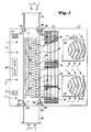
- the ventilation device shown in FIGS. 1 to 3 is intended for a farm tractor.
- a housing 10 of Ventilation devices are an evaporator and heating unit 12 as well as in their direction of travel of the tractor two radial fans 14 arranged in the front area.
- the lower area of the evaporator and heating unit 12 will Condensate water collected 16, which does not have one hose shown, which can be connected to a pipe socket 18 is, can be derived.
- the housing 10 is closed by a cover 20 and one seal shown can be closed. It points to its two Side mounting holes 22 on the, not shown Straps can be screwed on. Through the tabs you can Ventilation device from the inside in the front roof area of the Fasten the vehicle cabin, not shown in detail.
- the housing 10 has a service opening 24 which is open at the bottom and into which a filter housing 26 can be inserted below.
- a fresh air filter 28 for example a paper filter
- two wing screws 30 Can be attached without the use of tools.
- a housing cover 34 screwed.
- the Housing cover 34 carries two rows of webs 36 that face up have and between which a recirculation filter 38, for example a foam filter that can be pinched.
- a partition 40 is arranged around the incoming Separate the fresh air flow from the circulating air flow.
- the Housing cover 34 has an intake grille, in particular Air inlet grille 42, which serves as a air inlet opening serves.
- the air intake grille 42 can not with shown setting means, for. B. a slide provided through which the air inlet cross-section changes lets to adjust the circulating air flow variably.
- the front one with respect to the direction of travel of the tractor Side wall 44 of filter housing 26 has openings 46 on, through which the fresh air filter 28 and the Air recirculation filter 38 exiting air to the evaporator and Heating unit 12 can flow.
- the rear side wall 48 of the Filter housing 26 is closed.
- the filter housing 26 is open on the side so that, as will be explained later, Fresh air can flow in.
- the filter housing 26 is at the top also open.
- the front side wall 44 and the rear Side wall 48 of the filter housing 26 are for their stabilization connected to one another by connecting bridges 49.
- the filter housing 26, the fresh air filter 28, the circulating air filter 38, the partition 40 and the housing cover 34 can be assemble a filter insert, which from below into the Service opening 24 of the housing 10 can be inserted.
- the filter housing 26 has one on each side front flange 50 and a rear flange 52.
- the Flanges 50, 52 are in corresponding in the housing 10 trained, guide elements 54, 56, the groove-shaped are trained, led.
- For sealing are in the front Guide grooves 56 sealing profiles 58 inserted.
- the lid 20 has a transverse, upward curvature 60 through which a downwardly open groove is formed, which a sealing tape 62 receives.
- the upper one is supported in this groove Edge region 63 of the front side 44 of the filter housing 26, see above that the front side wall 44 is guided and sealing on the lid 20 is present.
- the sealing profiles 58 and the sealing tape 62 are used Sealing the clean air side from the raw air side.
- the filter insert When the filter insert is removed, go through the service opening 24 convenient access to components of the ventilation device or other components arranged in the housing 10 possible.
- the evaporator and heating unit 12 can be one Visually inspect to determine if they are is dirty and must be cleaned.
- electrical components which are arranged in the housing 10 for Maintenance work accessible. Such components can for example on the direction of travel of the Tractor rear rear wall 66 of the housing 10, which as Control and display panel can be used. Representative of such components are in the figures an interior light 68 and two switches 70 indicated.
- Outlet nozzles 72 There are two at the front on the underside of the housing 10 Outlet nozzles 72 through which the two blowers 14 conveyed air enters the cabin immediately.
- the Outlet nozzles 72 are each directly on the Outlet port 74 of the associated blower 14. They are eccentrically supported and have inclined ribs. This allows an optimal air flow and the Operator can by rotating the outlet nozzles 72 and ventilation by adjusting the inclination of your ribs adjust the cabin as required.
- the fresh air F is via inlet openings, not shown in the rear, side cabin roof area sucked in and between Forwarded inside and outside roof. Then she kicks over two short air channels 76 in the housing 10, and flows through the Fresh air filter 28.
- the circulating air U is through the Air intake grille 42 sucked into the filter housing 28 and flows through the air filter 38.
- the two air flows F and U run essentially in parallel through their associated filter 28, 38. In principle, it is also possible to have a common To use filter, which of the fresh air F and the recirculation U is flowed through.
- each of the radial fans 14 is not closer by one shown electric motor driven and sucks the air from its two axial sides.
Landscapes
- Engineering & Computer Science (AREA)
- Mechanical Engineering (AREA)
- Air-Conditioning For Vehicles (AREA)
Abstract
Description
- Fig. 1
- eine erfindungsgemäße Belüftungseinrichtung in Explosionsdarstellung,
- Fig. 2
- eine schematische Seitenschnittansicht der in Fig. 1 dargestellten Belüftungseinrichtung und
- Fig. 3
- eine schematische Aufsicht der in Fig. 1 dargestellten Belüftungseinrichtung.
Claims (12)
- Belüftungseinrichtung für eine Fahrzeugkabine, insbesondere für die Kabine eines landwirtschaftlichen oder industriellen Fahrzeugs, mit einem Gehäuse (10) und wenigstens einem darin angeordneten Gebläse (14), das Frischluft (F) von wenigstens einer äußeren Eintrittsöffnung der Fahrzeugkabine und/oder Umluft (U) von wenigstens einer sich ins Kabineninnere öffnenden Umlufteintrittsöffnung (42) zu wenigstens einer ins Kabineninnere mündenden Austrittsöffnung (72) fördert, und mit einer Filtereinheit, die sich wahlweise durch eine Serviceöffnung (24) im wesentlichen quer zum Luftstrom in das Gehäuse (10) derart einschieben läßt, daß sie von der Frischluft (F) und der Umluft (U) durchströmt wird, dadurch gekennzeichnet, daß die Filtereinheit ein Filtergehäuse (26) enthält, welches wenigstens einen Frischluftfilter (28) und wenigstens einen separaten Umluftfilter (38) aufnimmt, die hinsichtlich der Luftströme (F, U) nebeneinander angeordnet sind und zwischen denen wenigstens eine Trennwand (40) ausgebildet ist, welche eine getrennte Filterung von Frischluft (F) und Umluft (U) ermöglicht.
- Belüftungseinrichtung nach Anspruch 1, dadurch gekennzeichnet, daß sich die Frischluft- und Umluftströme (F, U) nach der Filterung vereinigen und vermischen und gemeinsam von wenigstens einem Gebläse (14) gefördert werden.
- Belüftungseinrichtung nach Anspruch 1 oder 2, dadurch gekennzeichnet, daß Einstellmittel im Ansaugbereich des Frischluftstroms (F) und/oder Umluftstroms (U) vorgesehen sind, durch die eine wahlweise Drosselung der Luftströme (F, U) möglich ist.
- Belüftungseinrichtung nach einem der Ansprüche 1 bis 3, dadurch gekennzeichnet, daß die Belüftungseinrichtung im Dach der Fahrzeugkabine anordenbar ist, daß die Frischluft (F) im Dachbereich der Kabine von außen angesaugt wird und daß die Serviceöffnung (24) sich im Kabineninneren befindet.
- Belüftungseinrichtung nach einem der Ansprüche 1 bis 4, dadurch gekennzeichnet, daß die Belüftungseinrichtung im Dach der Fahrzeugkabine anordenbar ist und daß das Filtergehäuse (26) im wesentlichen von unten nach oben durch die nach unten offene Serviceöffnung (24) in den Luftstrom (F, U) einschiebbar ist.
- Belüftungseinrichtung nach Anspruch 5, dadurch gekennzeichnet, daß im oberen Bereich des Filtergehäuses (26) wenigstens ein Frischluftfilter (28) und im unteren Bereich des Filtergehäuses (26) wenigstens ein Umluftfilter (38) angeordnet ist.
- Belüftungseinrichtung nach einem der Ansprüche 1 bis 6, dadurch gekennzeichnet, daß sich die wenigstens eine Umlufteintrittsöffnung (42) im Filtergehäuse (26) befindet.
- Belüftungseinrichtung nach einem der Ansprüche 1 bis 7, dadurch gekennzeichnet, daß das Filtergehäuse (26) durch zwei Sterngriffschrauben (64) in seiner Einbaulage fixierbar ist und daß der Frischluftfilter (28) und/oder der Umluftfilter (38) mit Hilfe von Flügelschrauben (30) im Filtergehäuse (26) befestigbar ist.
- Belüftungseinrichtung nach einem der Ansprüche 1 bis 8, dadurch gekennzeichnet, daß die Führung des Filtergehäuses (26) in dem Gehäuse (10) der Belüftungseinrichtung durch wenigstens zwei in einer Führungsschiene (54, 56, 60) geführte Flansche (50, 52, 63) erfolgt.
- Filtereinschub für eine Belüftungseinrichtung nach einem der Ansprüche 1 bis 9, mit einem Filtergehäuse (26), dadurch gekennzeichnet, daß das Filtergehäuse (26) wenigstens einen Frischluftfilter (28) und wenigstens einen Umluftfilter (38) aufnimmt, die hinsichtlich des Luftstroms (F, U) nebeneinander angeordnet sind und zwischen denen wenigstens eine Trennwand (40) ausgebildet ist, welche eine getrennte Filterung von Frischluft (F) und Umluft (U) ermöglicht.
- Filtereinschub nach Anspruch 10, dadurch gekennzeichnet, daß das Filtergehäuse (26) Führungselemente (54, 56, 60) aufweist, die dem Einschieben durch eine Serviceöffnung (24) des Gehäuses (10) der Belüftungseinrichtung in den quer zur Einschubrichtung ausgerichteten Luftstrom (F, U) dienen.
- Filtereinschub nach Anspruch 10 oder 11, dadurch gekennzeichnet, daß das Filtergehäuse (26) wenigstens eine Eintrittsöffnung (42) für die Umluft (U) aufweist, welche bei in die Serviceöffnung (24) des Gehäuses (10) eingeschobenem Filtereinschub nach außen offen ist und den unmittelbaren Eintritt von Kabinenluft (U) ermöglicht.
Applications Claiming Priority (2)
| Application Number | Priority Date | Filing Date | Title |
|---|---|---|---|
| DE19628089A DE19628089C2 (de) | 1996-07-12 | 1996-07-12 | Belüftungseinrichtung für eine Fahrzeugkabine und Filtergehäuse |
| DE19628089 | 1996-07-12 |
Publications (3)
| Publication Number | Publication Date |
|---|---|
| EP0818338A2 true EP0818338A2 (de) | 1998-01-14 |
| EP0818338A3 EP0818338A3 (de) | 1999-06-16 |
| EP0818338B1 EP0818338B1 (de) | 2003-07-30 |
Family
ID=7799616
Family Applications (1)
| Application Number | Title | Priority Date | Filing Date |
|---|---|---|---|
| EP97111308A Expired - Lifetime EP0818338B1 (de) | 1996-07-12 | 1997-07-04 | Belüftungseinrichtung für eine Fahrzeugkabine und Filtergehäuse |
Country Status (8)
| Country | Link |
|---|---|
| US (1) | US5860856A (de) |
| EP (1) | EP0818338B1 (de) |
| JP (1) | JPH10147128A (de) |
| AR (1) | AR007697A1 (de) |
| AT (1) | ATE246100T1 (de) |
| BR (1) | BR9703948A (de) |
| CA (1) | CA2209429C (de) |
| DE (2) | DE19628089C2 (de) |
Cited By (3)
| Publication number | Priority date | Publication date | Assignee | Title |
|---|---|---|---|---|
| EP1623860A1 (de) * | 2004-08-03 | 2006-02-08 | Valeo Systemes Thermiques | Belüftungsmodul für einen Fahrzeuginnenraum |
| EP2127922A1 (de) * | 2008-05-28 | 2009-12-02 | Behr France Rouffach SAS | Heizungssystem eines Kraftfahrzeuges, Rahmen einer elektrischen Heizeinrichtung und Aufnahme für eine elektrische Heizeinrichtung |
| FR2966052A1 (fr) * | 2010-10-18 | 2012-04-20 | Atlantic Climatisation Et Ventilation | Dispositif de filtration d'air et unite de ventilation munie d'un tel dispositif de filtration |
Families Citing this family (37)
| Publication number | Priority date | Publication date | Assignee | Title |
|---|---|---|---|---|
| GB2356359A (en) * | 1999-11-19 | 2001-05-23 | Albert Robert Lowes | Air return register with filter and fresh air inlet |
| GB2364000B (en) * | 2000-06-29 | 2004-02-25 | Valeo Climate Control Ltd | Air filter for vehicle ventilation |
| US6283849B1 (en) | 2000-10-05 | 2001-09-04 | Specific Cruise Systems, Inc. | Vehicle filtration control system |
| DE10141986A1 (de) * | 2001-08-28 | 2003-03-20 | Deere & Co | Luftfiltersystem für Fahrzeugkabinen |
| US6517138B1 (en) | 2001-08-29 | 2003-02-11 | Deere & Company | Recessed air conditioning controls for a utility vehicle |
| GB2381216B (en) | 2001-10-26 | 2005-05-11 | Agco Sa | Air conditioning filter |
| DE10164374A1 (de) * | 2001-12-28 | 2003-07-17 | Valeo Klimasysteme Gmbh | Klimaanlage mit Vorrichtung zur Regelung des Einlasses von Frisch- und Umluft |
| DE10245689A1 (de) * | 2002-10-01 | 2004-04-15 | Deere & Company, Moline | Überwachungseinrichtung für Raumluftverunreinigung |
| DE10307750A1 (de) * | 2003-02-14 | 2004-09-02 | Carl Freudenberg Kg | Vorrichtung zur Aufnahme eines Filtereinsatzes |
| US7252585B2 (en) * | 2003-06-12 | 2007-08-07 | Kubota Corporation | Work-vehicle cabin having air-conditioning unit |
| DE102004054169B3 (de) * | 2004-09-20 | 2006-04-13 | Konvekta Ag | Klimagerät |
| BRPI0520444A2 (pt) * | 2005-07-29 | 2009-06-13 | Carrier Corp | unidade de evaporador de condicionamento de ar |
| US7334834B2 (en) * | 2006-03-09 | 2008-02-26 | Deere & Company | Tractor cab roof with integral HVAC air ducts |
| US7377848B2 (en) | 2006-07-12 | 2008-05-27 | Cnh America Llc | Filter purge control for HVAC variable air circulation system |
| US7338357B2 (en) * | 2006-07-12 | 2008-03-04 | Cnh America Llc | Filter purge control for HVAC fixed air circulation system |
| IT1390714B1 (it) * | 2008-07-11 | 2011-09-15 | Spal Automotive Srl | Sistema di ventilazione |
| US20130001984A1 (en) * | 2011-06-28 | 2013-01-03 | Caterpillar Inc. | System for controlling temperature in a machine cab |
| US9975405B2 (en) | 2013-03-14 | 2018-05-22 | Dometic Corporation | Modular air grill assembly |
| DE102014224919A1 (de) * | 2014-01-20 | 2015-08-06 | MAHLE Behr GmbH & Co. KG | Straßenfahrzeug |
| DE102014204162B4 (de) * | 2014-03-06 | 2023-11-09 | Audi Ag | Filtervorrichtung für eine Brennstoffzelle |
| DE102015112432A1 (de) * | 2015-07-29 | 2017-02-02 | Alija Dzemaili | Klimaanlage |
| USD850609S1 (en) | 2015-10-15 | 2019-06-04 | Dometic Sweden Ab | Modular air grill |
| AU2017101887A4 (en) | 2016-01-16 | 2020-10-08 | Dometic Sweden Ab | Parking cooler |
| USD817466S1 (en) | 2016-01-19 | 2018-05-08 | Dometic Sweden Ab | Air shroud assembly |
| AU367405S (en) | 2016-02-12 | 2016-03-01 | Dometic Sweden Ab | Recreational vehicle air-conditioning unit |
| WO2017143393A1 (en) | 2016-02-22 | 2017-08-31 | Dometic Sweden Ab | Vehicle air conditioner |
| WO2017143394A1 (en) | 2016-02-22 | 2017-08-31 | Dometic Sweden Ab | Air-conditioner control |
| AU201612249S (en) | 2016-04-28 | 2016-05-31 | Dometic Sweden Ab | Air-conditioning unit |
| AU201712794S (en) | 2016-11-23 | 2017-05-23 | Dometic Sweden Ab | Ventilation and air conditioning apparatus |
| USD915569S1 (en) | 2017-02-17 | 2021-04-06 | Dometic Sweden Ab | Shroud assembly |
| CN106882017B (zh) * | 2017-03-02 | 2023-08-04 | 成都易态科技有限公司 | 客运车厢空气净化系统及其控制方法 |
| DE112018005883B4 (de) | 2017-11-16 | 2025-12-18 | Dometic Sweden Ab | Klimatisierungsvorrichtung für Wohnmobile, Wohnmobil und Verfahren zur Zufuhr von klimatisierter Luft in einem Wohnmobil |
| USD905217S1 (en) | 2018-09-05 | 2020-12-15 | Dometic Sweden Ab | Air conditioning apparatus |
| FR3093164A1 (fr) * | 2019-02-25 | 2020-08-28 | Valeo Systemes Thermiques | Boîtier pour dispositif de chauffage, climatisation et/ou ventilation pour véhicule automobile |
| US11186145B2 (en) * | 2019-05-30 | 2021-11-30 | Denso International America, Inc. | Cabin air filter tray |
| IT201900019193A1 (it) | 2019-10-17 | 2021-04-17 | Dometic Sweden Ab | Apparato di condizionamento dell'aria per veicoli ricreativi |
| DE202020002697U1 (de) | 2020-06-22 | 2021-09-23 | Frank Johne | Landfahrzeug |
Family Cites Families (10)
| Publication number | Priority date | Publication date | Assignee | Title |
|---|---|---|---|---|
| SE423356B (sv) * | 1978-04-18 | 1982-05-03 | Saab Scania Ab | Arrangemang for rening av inledande luft till ett fordons kupeutrymme |
| US4344356A (en) * | 1980-06-23 | 1982-08-17 | Deere & Company | Air distribution system |
| US4365541A (en) * | 1980-12-12 | 1982-12-28 | Caterpillar Tractor Co. | Filter arrangement for an air circulatory system |
| EP0070636B1 (de) * | 1981-07-16 | 1986-04-16 | Massey-Ferguson Services N.V. | Kabine mit Heizungs- und/oder Belüftungssystem |
| US4531453A (en) * | 1983-05-16 | 1985-07-30 | Deere & Company | Atmosphere control arrangement for an operator enclosure |
| DE3545866A1 (de) * | 1985-12-23 | 1987-06-25 | Hagenuk Telecom Gmbh | Luftbehandlungsgeraet zur klimatisierung von fahrzeugen |
| DE3643478A1 (de) * | 1986-12-19 | 1988-07-07 | Kloeckner Humboldt Deutz Ag | Luftfilterkasten fuer eine fahrerkabine |
| DE3837967A1 (de) * | 1988-11-09 | 1990-05-10 | Daimler Benz Ag | Heizungs- oder klimaanlage fuer einen kraftwagen |
| US4989500A (en) * | 1990-01-10 | 1991-02-05 | J. I. Case Company | Cab duct arrangment for service of air filters through a single access opening |
| JP2831174B2 (ja) * | 1991-09-10 | 1998-12-02 | 株式会社クボタ | キャビン装置のエアコン外気導入構造 |
-
1996
- 1996-07-12 DE DE19628089A patent/DE19628089C2/de not_active Expired - Fee Related
-
1997
- 1997-07-01 US US08/886,376 patent/US5860856A/en not_active Expired - Fee Related
- 1997-07-01 AR ARP970102943A patent/AR007697A1/es unknown
- 1997-07-04 CA CA002209429A patent/CA2209429C/en not_active Expired - Fee Related
- 1997-07-04 AT AT97111308T patent/ATE246100T1/de not_active IP Right Cessation
- 1997-07-04 EP EP97111308A patent/EP0818338B1/de not_active Expired - Lifetime
- 1997-07-04 DE DE59710497T patent/DE59710497D1/de not_active Expired - Fee Related
- 1997-07-10 BR BR9703948A patent/BR9703948A/pt not_active IP Right Cessation
- 1997-07-14 JP JP9188027A patent/JPH10147128A/ja active Pending
Cited By (4)
| Publication number | Priority date | Publication date | Assignee | Title |
|---|---|---|---|---|
| EP1623860A1 (de) * | 2004-08-03 | 2006-02-08 | Valeo Systemes Thermiques | Belüftungsmodul für einen Fahrzeuginnenraum |
| FR2873954A1 (fr) * | 2004-08-03 | 2006-02-10 | Valeo Climatisation Sa | Module de ventilation d'air pour un habitacle de vehicule |
| EP2127922A1 (de) * | 2008-05-28 | 2009-12-02 | Behr France Rouffach SAS | Heizungssystem eines Kraftfahrzeuges, Rahmen einer elektrischen Heizeinrichtung und Aufnahme für eine elektrische Heizeinrichtung |
| FR2966052A1 (fr) * | 2010-10-18 | 2012-04-20 | Atlantic Climatisation Et Ventilation | Dispositif de filtration d'air et unite de ventilation munie d'un tel dispositif de filtration |
Also Published As
| Publication number | Publication date |
|---|---|
| CA2209429C (en) | 2000-10-31 |
| EP0818338A3 (de) | 1999-06-16 |
| ATE246100T1 (de) | 2003-08-15 |
| CA2209429A1 (en) | 1998-01-12 |
| US5860856A (en) | 1999-01-19 |
| DE59710497D1 (de) | 2003-09-04 |
| EP0818338B1 (de) | 2003-07-30 |
| AR007697A1 (es) | 1999-11-10 |
| BR9703948A (pt) | 1998-09-01 |
| JPH10147128A (ja) | 1998-06-02 |
| DE19628089A1 (de) | 1998-01-15 |
| DE19628089C2 (de) | 1998-12-03 |
Similar Documents
| Publication | Publication Date | Title |
|---|---|---|
| EP0818338B1 (de) | Belüftungseinrichtung für eine Fahrzeugkabine und Filtergehäuse | |
| EP0438076B1 (de) | Belüftungseinrichtung für Fahrzeugkabine | |
| EP0125562B1 (de) | Luftversorgungsvorrichtung für die Fahrerkabine eines Fahrzeuges | |
| DE102011051489B4 (de) | Gebläse-Luftansaugungsvorrichtung | |
| DE10046935B4 (de) | Heiz- und gegebenenfalls Klimagerät für Nutzfahrzeuge, z. B. Omnibusse | |
| DE69301785T2 (de) | Vorrichtung für die Heizung, Lüftung und/oder Klimatisierung eines Fahrzeuginnenraumes | |
| DE102004004197A1 (de) | Zweiteilig ausgebildete Dachstruktur | |
| EP0042597A2 (de) | Luftverteileinrichtung | |
| DE2915501A1 (de) | Lueftungsanlage fuer ein fahrzeug | |
| DE3930429A1 (de) | Klimaanlage fuer kraftfahrzeuge, insbesondere omnibusse | |
| EP0200899B1 (de) | Vorrichtung zur Belüftung und Klimatisierung von Fahrerplätzen, Fahrerhäusern od. dgl. | |
| DE1455863A1 (de) | Klimaanlage fuer Kraftfahrzeuge | |
| EP0353412A2 (de) | Heizungs- und/oder Klimaanlage für ein Kraftfahrzeug | |
| EP1228907B1 (de) | Klimagerät für ein Kraftfahrzeug | |
| DE10012972C1 (de) | Belüftungsvorrichtung für Fahrzeuge | |
| DE3923307C2 (de) | ||
| EP0745034B1 (de) | Heizungs- oder klimaanlage für ein kraftfahrzeug | |
| DE10209132B4 (de) | Ansaugvorrichtung für Kaltluft | |
| DE4435292C2 (de) | Klimagerät | |
| DE10147114A1 (de) | Vorrichtung und Verfahren zum Temperieren und Belüften von Kraftfahrzeugen | |
| DE9420222U1 (de) | Anordnung von Bauteilen zur Belüftung, Heizung und/oder Klimatisierung eines Kraftfahrzeugs | |
| EP2154011A1 (de) | Klimaanlage mit Gebläse, insbesondere in einer Land- oder Baumaschine | |
| EP3424759B1 (de) | Kabinendach einer kabine für ein landwirtschaftliches arbeitsfahrzeug | |
| DE19703461A1 (de) | Heizungs- oder Klimaanlage für Kraftfahrzeuge | |
| DE4240440C1 (de) | Belüftungsvorrichtung für Fahrzeuge |
Legal Events
| Date | Code | Title | Description |
|---|---|---|---|
| PUAI | Public reference made under article 153(3) epc to a published international application that has entered the european phase |
Free format text: ORIGINAL CODE: 0009012 |
|
| AK | Designated contracting states |
Kind code of ref document: A2 Designated state(s): AT DE FR GB IT |
|
| PUAL | Search report despatched |
Free format text: ORIGINAL CODE: 0009013 |
|
| AK | Designated contracting states |
Kind code of ref document: A3 Designated state(s): AT BE CH DE DK ES FI FR GB GR IE IT LI LU MC NL PT SE |
|
| RIC1 | Information provided on ipc code assigned before grant |
Free format text: 6B 60H 3/06 A, 6B 60H 1/00 B |
|
| 17P | Request for examination filed |
Effective date: 19990706 |
|
| AKX | Designation fees paid |
Free format text: AT DE FR GB IT |
|
| 17Q | First examination report despatched |
Effective date: 20020723 |
|
| GRAH | Despatch of communication of intention to grant a patent |
Free format text: ORIGINAL CODE: EPIDOS IGRA |
|
| GRAH | Despatch of communication of intention to grant a patent |
Free format text: ORIGINAL CODE: EPIDOS IGRA |
|
| GRAA | (expected) grant |
Free format text: ORIGINAL CODE: 0009210 |
|
| AK | Designated contracting states |
Designated state(s): AT DE FR GB IT |
|
| REG | Reference to a national code |
Ref country code: GB Ref legal event code: FG4D Free format text: NOT ENGLISH |
|
| RAP2 | Party data changed (patent owner data changed or rights of a patent transferred) |
Owner name: DEERE & COMPANY |
|
| REF | Corresponds to: |
Ref document number: 59710497 Country of ref document: DE Date of ref document: 20030904 Kind code of ref document: P |
|
| GBT | Gb: translation of ep patent filed (gb section 77(6)(a)/1977) |
Effective date: 20031015 |
|
| ET | Fr: translation filed | ||
| PLBE | No opposition filed within time limit |
Free format text: ORIGINAL CODE: 0009261 |
|
| STAA | Information on the status of an ep patent application or granted ep patent |
Free format text: STATUS: NO OPPOSITION FILED WITHIN TIME LIMIT |
|
| 26N | No opposition filed |
Effective date: 20040504 |
|
| PGFP | Annual fee paid to national office [announced via postgrant information from national office to epo] |
Ref country code: DE Payment date: 20070619 Year of fee payment: 11 |
|
| PGFP | Annual fee paid to national office [announced via postgrant information from national office to epo] |
Ref country code: AT Payment date: 20070620 Year of fee payment: 11 |
|
| PGFP | Annual fee paid to national office [announced via postgrant information from national office to epo] |
Ref country code: GB Payment date: 20070727 Year of fee payment: 11 |
|
| PGFP | Annual fee paid to national office [announced via postgrant information from national office to epo] |
Ref country code: IT Payment date: 20070726 Year of fee payment: 11 |
|
| PGFP | Annual fee paid to national office [announced via postgrant information from national office to epo] |
Ref country code: FR Payment date: 20070717 Year of fee payment: 11 |
|
| GBPC | Gb: european patent ceased through non-payment of renewal fee |
Effective date: 20080704 |
|
| PG25 | Lapsed in a contracting state [announced via postgrant information from national office to epo] |
Ref country code: DE Free format text: LAPSE BECAUSE OF NON-PAYMENT OF DUE FEES Effective date: 20090203 Ref country code: AT Free format text: LAPSE BECAUSE OF NON-PAYMENT OF DUE FEES Effective date: 20080704 |
|
| REG | Reference to a national code |
Ref country code: FR Ref legal event code: ST Effective date: 20090331 |
|
| PG25 | Lapsed in a contracting state [announced via postgrant information from national office to epo] |
Ref country code: GB Free format text: LAPSE BECAUSE OF NON-PAYMENT OF DUE FEES Effective date: 20080704 |
|
| PG25 | Lapsed in a contracting state [announced via postgrant information from national office to epo] |
Ref country code: IT Free format text: LAPSE BECAUSE OF NON-PAYMENT OF DUE FEES Effective date: 20080704 Ref country code: FR Free format text: LAPSE BECAUSE OF NON-PAYMENT OF DUE FEES Effective date: 20080731 |