EP0818894B1 - Sender für optische Signale und optisches Übertragunssystem mit einem solchen Sender - Google Patents
Sender für optische Signale und optisches Übertragunssystem mit einem solchen Sender Download PDFInfo
- Publication number
- EP0818894B1 EP0818894B1 EP97111163A EP97111163A EP0818894B1 EP 0818894 B1 EP0818894 B1 EP 0818894B1 EP 97111163 A EP97111163 A EP 97111163A EP 97111163 A EP97111163 A EP 97111163A EP 0818894 B1 EP0818894 B1 EP 0818894B1
- Authority
- EP
- European Patent Office
- Prior art keywords
- signal light
- signal
- wavelengths
- lights
- optical
- Prior art date
- Legal status (The legal status is an assumption and is not a legal conclusion. Google has not performed a legal analysis and makes no representation as to the accuracy of the status listed.)
- Expired - Lifetime
Links
Images


Classifications
-
- H—ELECTRICITY
- H04—ELECTRIC COMMUNICATION TECHNIQUE
- H04J—MULTIPLEX COMMUNICATION
- H04J14/00—Optical multiplex systems
- H04J14/02—Wavelength-division multiplex systems
- H04J14/0221—Power control, e.g. to keep the total optical power constant
-
- H—ELECTRICITY
- H04—ELECTRIC COMMUNICATION TECHNIQUE
- H04B—TRANSMISSION
- H04B10/00—Transmission systems employing electromagnetic waves other than radio-waves, e.g. infrared, visible or ultraviolet light, or employing corpuscular radiation, e.g. quantum communication
- H04B10/50—Transmitters
- H04B10/501—Structural aspects
- H04B10/506—Multiwavelength transmitters
-
- H—ELECTRICITY
- H04—ELECTRIC COMMUNICATION TECHNIQUE
- H04B—TRANSMISSION
- H04B10/00—Transmission systems employing electromagnetic waves other than radio-waves, e.g. infrared, visible or ultraviolet light, or employing corpuscular radiation, e.g. quantum communication
- H04B10/50—Transmitters
- H04B10/564—Power control
Definitions
- This invention relates to a signal light outputting apparatus suitable for use as a transmission apparatus for transmitting a plurality of signal lights of different wavelengths in an optical transmission system wherein optical communication is performed by wavelength multiplexing transmission, and also to an optical transmission system having a signal light outputting apparatus of the type mentioned.
- an optical transmission system In order to allow communication of signal light between terminal stations spaced from each other, for example, with a sea interposed therebetween, an optical transmission system has been developed wherein an optical fiber cable is laid on the bottom of the sea and signal light is repeated and amplified in a plurality of stages using a plurality of optical amplifiers provided for the optical fiber cable.
- the optical transmission system generally denoted at 100 is constructed to effect bidirectional communication between a plurality of terminal stations, and includes, as such plurality of terminal stations, for example, an A station 101, a B station 102, a C station 103 and a D station 104.
- the A to D stations 101 to 104 are connected to each other by optical transmission lines 107 each formed from an optical fiber via light branching and insertion apparatus 105 and 106.
- the A station 101 and the C station 103 are connected to each other with the light branching and insertion apparatus 105 interposed therebetween, and the B station 102 and the D station 104 are connected to each other with the light branching and insertion apparatus 106 interposed therebetween.
- the A station 101 and the B station 102, the A station 101 and the D station 104, the B station 102 and the C station 103, and the C station 103 and the D station 104, are connected to each other with the light branching and insertion apparatus 105 and 106 interposed therebetween.
- Each of the A to D stations 101 to 104 includes a plurality of transmission-reception apparatus each including a transmission apparatus 109 for transmitting signal light of a single wavelength and a reception apparatus 110 for receiving signal light transmitted from the transmission apparatus 109 of a different one of the transmission-reception apparatus.
- a plurality of optical amplifiers 108 for amplifying signal light to be transmitted in a plurality of stages are provided for each of the optical transmission lines 107.
- signal light is communicated among the A to D stations 101 to 104.
- an optical transmission system which employs such an optical transmission line or optical amplifier for WDM or light branching and insertion apparatus as just mentioned, a plurality of signal lights of different wavelengths are transmitted by means of a single optical transmission line, and the plurality of signal lights of the different wavelengths transmitted in this manner are amplified by a single optical amplifier and branching (wave separation or demultiplexing) or insertion (wave combination or multiplexing) of the signal light is performed depending upon the wavelength so that the signal lights are transmitted to desired terminal stations.
- pre-emphasis which varies the ratios of the powers of the signal lights is performed so that the S/N ratios of the signal lights after transmitted may be equal to each other.
- automatic power control is performed such that back powers of laser diodes (LDs) which output the signal lights are monitored and the output powers of the laser diodes are adjusted in response to the magnitudes of the back powers so that the powers of the signal lights may always have values equal to those set by the pre-emphasis.
- LDs laser diodes
- control of the powers of signal lights is performed by varying the outputs of laser diodes. Where the outputs of the laser diodes are varied in this manner, since the temperature in the proximity of each laser diode varies, the wavelength of the output signal light from the laser diode varies.
- the optical transmission lines 107 are provided individually for the signal lights, even if the wavelengths of the output signal lights vary a little, transmission and reception of the signal lights can be performed with certainty.
- the optical transmission system for WDM wherein optical wavelength multiplexing transmission is performed, if the wavelengths of output signal light vary, then the branching-insertion characteristic of signal light of a light branching and insertion apparatus sometimes varies. Accordingly, the optical transmission system has another subject to be solved in that, in such an instance as just described, transmission and reception of signal light'cannot be performed accurately.
- US-A-5 589 970 there is described a locking apparatus for an optical frequency multiplex system.
- a local oscillation unit applies low frequency signals to individual light sources, thereby making the center frequencies of the light sources dither.
- the dithering optical signals are grouped by photocouplers, and a resonator is employed for aligning the signals coupled by the photocouplers with optical frequency slots, thereby to obtain an equidistant optical frequency-multiplexed output.
- a signal light outputting apparatus comprising a plurality of signal light outputting units each including a signal light source for outputting a signal light of a respective wavelength and an optical amplifier for amplifying the signal light outputted from the signal light source, an optical combiner for combining a plurality of signal lights of different wavelengths outputted from the signal light outputting units, a signal light power detector for extracting part of signal light combined by the optical combiner to detect powers of the signal light for individual wavelengths corresponding td the signal light wavelengths of the signal light sources, and a signal light output controller for controlling the optical amplifiers in response to the powers of the signal lights of the individual wavelengths detected by the signal light power detector, whereby to control the power of the signal light output from each of the plurality of optical amplifiers and the powers of the signal lights combined by the optical .combiner.
- the signal light outputting apparatus is constructed such that the signal light output controller includes a signal light power comparison and discrimination section for comparing the powers of the signal lights of the individual wavelengths detected by the signal light power detector with preset powers of signal lights of the individual wavelengths to discriminate whether or not the powers of the signal lights of the individual wavelengths detected by the signal light power detector are equal to the preset powers of the signal lights of the individual wavelengths, and controls the signal light outputs of the corresponding optical amplifiers for amplification of the signal lights of the wavelengths in response to results of the comparison and discrimination by the signal light power comparison and discrimination section.
- the signal light output controller includes a signal light power comparison and discrimination section for comparing the powers of the signal lights of the individual wavelengths detected by the signal light power detector with preset powers of signal lights of the individual wavelengths to discriminate whether or not the powers of the signal lights of the individual wavelengths detected by the signal light power detector are equal to the preset powers of the signal lights of the individual wavelengths, and controls the signal light outputs of the corresponding optical amplifiers for
- the signal light outputting apparatus is constructed such that the signal light power detector includes an optical spectrum analyzer.
- the signal light outputting apparatus may be constructed such that the signal light power detector includes an optical separator for extracting part of the signal light combined by the optical combiner and separating the extracted signal light into signal lights of the individual wavelengths corresponding to the signal light wavelengths of the signal light sources, and a plurality of photo-electric converters for converting the signal lights separated by the optical separator into electric signals.
- the signal light power detector includes an optical separator for extracting part of the signal light combined by the optical combiner and separating the extracted signal light into signal lights of the individual wavelengths corresponding to the signal light wavelengths of the signal light sources, and a plurality of photo-electric converters for converting the signal lights separated by the optical separator into electric signals.
- the signal light outputting apparatus in order to control the powers of signal lights of different wavelengths of signal light combined by the .. optical combiner, the signal light outputs of the corresponding optical amplifiers for amplification of the signal lights of the wavelengths are controlled. Consequently, the signal light outputting apparatus is advantageous in that the ratio of the powers of the signal lights set by pre-emphasis can be controlled with certainty.
- a signal light wavelength detector may be provided for extracting part of signal light combined by the optical combiner to detect wavelengths of the signal light for individual wavelengths corresponding to the signal light wavelengths of the signal light sources, and the signal light output controller may also control the signal light sources in response to the wavelengths of the signal lights detected by the signal light wavelength detector, whereby to control the wavelength output from each of the signal light sources and the wavelengths of the signal lights combined by the optical combiner.
- the signal light outputting apparatus is constructed such that the signal light output controller includes a signal light wavelength comparison and discrimination section for comparing the signal light wavelengths of the individual signal light sources detected by the signal light wavelength detector with preset signal light wavelengths of the individual signal light sources to discriminate whether or not the signal light wavelengths of the individual signal light sources detected by the signal light wavelength detector are equal to the preset signal light wavelengths of the individual signal light sources, and controls the signal light wavelengths of the corresponding signal light sources for outputting of the signal lights of the wavelengths in response to results of the comparison and discrimination by the signal light wavelength comparison and discrimination section.
- the signal light output controller includes a signal light wavelength comparison and discrimination section for comparing the signal light wavelengths of the individual signal light sources detected by the signal light wavelength detector with preset signal light wavelengths of the individual signal light sources to discriminate whether or not the signal light wavelengths of the individual signal light sources detected by the signal light wavelength detector are equal to the preset signal light wavelengths of the individual signal light sources, and controls the signal light wavelengths of the corresponding signal light sources
- the signal light outputting apparatus is constructed such that it further comprises a light source temperature adjustment member provided for each of the signal light sources, and the signal light wavelength controller controls the light source temperature adjustment members provided for the individual signal light sources for outputting of the signal lights of the wavelengths to control the signal light wavelengths of the corresponding signal light sources.
- the signal light outputting apparatus is constructed such that the signal light wavelength detector includes an optical spectrum analyzer.
- the corresponding light source temperature adjustment members provided for the signal light sources for outputting of the signal lights of the wavelengths are controlled to control the wavelengths of the signal lights of the corresponding signal light sources for outputting of the signal lights of the wavelengths. Consequently, the signal light outputting apparatus is advantageous in that otherwise possible variation of the wavelengths of the signal lights can be controlled with certainty.
- the signal light outputting apparatus is constructed such that the signal light output controller includes a signal light power comparison and discrimination section for comparing the powers of the signal lights of the individual wavelengths detected by the signal light detection element with preset powers of signal lights of the individual wavelengths to discriminate whether or not the powers of the signal lights of the individual wavelengths detected by the signal light detection element are equal to the preset powers of the signal lights of the individual wavelengths, and controls the signal light outputs of the corresponding optical amplifiers for amplification of the signal lights of the wavelengths in response to results of the comparison and discrimination by the signal light power comparison and discrimination section.
- the signal light output controller includes a signal light power comparison and discrimination section for comparing the powers of the signal lights of the individual wavelengths detected by the signal light detection element with preset powers of signal lights of the individual wavelengths to discriminate whether or not the powers of the signal lights of the individual wavelengths detected by the signal light detection element are equal to the preset powers of the signal lights of the individual wavelengths, and controls the signal light outputs of the corresponding optical amplifiers for
- the signal light outputting apparatus is constructed such that each of the light source temperature adjustment member includes a Peltier element.
- the signal light outputting apparatus in order to control the powers and the wavelengths of signal lights of different wavelengths of signal light combined by the optical combiner, the signal light outputs of the corresponding optical amplifiers for amplification of the signal lights of the wavelengths are controlled and the corresponding light source temperature adjustment members provided for the signal light sources for outputting of the signal lights of the wavelengths are controlled to control the wavelengths of the signal lights of the corresponding signal light sources for outputting of the signal lights of the wavelengths. Consequently, otherwise possible variation of the wavelengths of the signal lights can be prevented while the ratio of the powers of the signal lights set by pre-emphasis can be controlled with certainty.
- an optical transmission system with a signal light outputting apparatus comprising a plurality of signal light outputting apparatus each including a plurality of signal light outputting units each including a signal light source for outputting a signal light of a respective wavelength and an optical amplifier for amplifying the signal light outputted from the signal light source, an optical combiner for combining a plurality of signal lights of different wavelengths outputted from the signal light outputting units, a signal light detection element for extracting part of signal light combined by the optical combiner to detect powers and wavelengths of the signal light for individual wavelengths corresponding to the signal light wavelengths of the signal light sources, a signal light output controller for controlling (a) the optical amplifiers in response to the powers of the signal lights of the individual wavelengths detected by the signal light detection element, whereby to control the power of the signal light output from each of the plurality of optical amplifiers and the powers of the signal lights combined by the optical combiner, and (b) the signal light sources in response to the wavelengths of the signal lights detected
- the optical transmission system With the optical transmission system with a signal light outputting apparatus, since it is constructed such that it includes a plurality of signal light outputting apparatus and a light branching and/or insertion apparatus provided at a branching point of the optical fiber system by which the plurality of signal light outputting apparatus are interconnected and signal light is communicated between the plurality of signal light outputting apparatus via the light branching and/or insertion apparatus, the optical transmission system is advantageous in that pre-emphasis when signal lights are outputted from the signal light outputting apparatus can be stabilized for a long period of time and a dispersion in transmission characteristic between the different signal lights can be suppressed to a minimum level and further in that variation in branching and insertion characteristic of the optical branching and/or insertion apparatus by variation in wavelength of the signal light can be prevented and communication of the signal light between the plurality of signal light outputting apparatus can be performed accurately.
- FIG. 2 shows in block diagram an optical transmission system in which a signal light outputting apparatus according to the present invention is incorporated.
- the optical transmission system shown is generally denoted at 10 and performs optical communication between a plurality of terminal stations by wavelength multiplexing (WDM) transmission.
- the optical transmission system 10 includes, as the plurality of terminal stations, for example, an A station 1, a B station 2 and a C station 3.
- the A to C stations 1 to 3 are connected to each other by optical transmission lines 5 each formed from an optical fiber via a light branching and insertion apparatus 4.
- the A station 1 includes a transmission apparatus 7 for outputting and transmitting a plurality of signal lights of different wavelengths and serves as a transmission station.
- the B station 2 includes a reception apparatus 8 for receiving signal light transmitted thereto from another terminal station (in FIG. 2, the A station 1 or the C station 3) and serves as a reception station.
- the C station 3 includes a transmission apparatus 7 for outputting and transmitting a plurality of signal lights of different wavelengths and a reception apparatus 8 for receiving signal light transmitted thereto from another terminal station (in FIG. 2, the A station 1) and serves as a transmission and reception station.
- a signal outputting apparatus is employed as the transmission apparatus 7 in any of the A to C stations 1 to 3 and has a construction and functions which will be hereinafter described in detail.
- the light branching and insertion apparatus 4 is provided at a branching point of the optical transmission lines 5 which interconnect a plurality of terminal stations (in FIG. 2, the A station 1, B station 2 and C station 3) and outputs a signal light of a desired wavelength inputted thereto from any of the terminal stations 1 to 3 to another desired one of the terminal stations 1 to 3 to allow transmission of the signal light between the desired ones of the terminal stations. Also the light branching and insertion apparatus 4 will be hereinafter described in detail.
- Each of the optical transmission lines 5 shown in FIG. 2 includes a plurality of optical amplifiers 6 interposed therein for repeating and amplifying signal light being transmitted in a plurality of stages.
- the optical transmission system 10 having the construction as described above with reference to FIG. 2, if a plurality of signal lights of different wavelengths are transmitted from the A station 1 while another signal light is transmitted from the C station 3, then those signal lights are inputted to the light branching and insertion apparatus 4 via suitable ones of the optical transmission lines 5.
- the light branching and insertion apparatus 4 combines or multiplexes the signal light of a desired wavelength from within the signal light transmitted thereto from the A station 1 with the signal light transmitted thereto from the C station 3 and outputs the thus combined signal light to the B station 2. In the meantime, the light branching and insertion apparatus 4 branches the signal lights of the other wavelengths from within the signal light transmitted thereto from the A station 1 and outputs the branched signal lights to the C station 3.
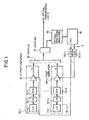
- FIG. 1 shows in block diagram a construction of a signal light outputting apparatus to which the present invention is applied.
- the signal light outputting apparatus 7 shown adjusts, when it outputs a plurality of signal lights ⁇ 1 to ⁇ n of different wavelengths, the powers of the signal lights ⁇ 1 to ⁇ n so that they may have values individually set in advance, and is used as a transmission apparatus in a plurality of terminals (in FIG. 2, the A to C stations 1 and 3) which transmit and receive, in such a system as the optical transmission system 10 shown in FIG. 2, signal light therebetween.
- the signal light outputting apparatus 7 includes signal light outputting units 15-1 to 15-n, a coupler 16, an optical spectrum analyzer 18 and a central processing unit (CPU) 19.
- CPU central processing unit
- the signal light outputting apparatus 7 further includes a 10:1 coupler 17, and digital to analog converters (D/A) 20-1 to 20-n.
- D/A digital to analog converters
- each route along which a signal light passes is indicated by a thick line while each route along which an electric signal passes is indicated by a thin line.
- the signal light outputting units 15-1 to 15-n output signal lights ⁇ 1 to ⁇ n having wavelengths different by 2 nm from each other within the wavelength range from 1,550 nm to 1560 nm.
- the signal light outputting unit 15-1 includes a laser diode (LD) 11-1 serving as a signal light source for outputting a signal light ( ⁇ 1 in FIG. 1) of a desired wavelength, a modulator (LN) 12-1 for modulating the signal light outputted from the laser diode 11-1, a scrambler (SCR) 13-1 for converting the signal light outputted from the modulator 12-1 into a random code series, and a post-amplifier 14-1 serving as an optical amplifier for amplifying the signal light outputted from the scrambler 13-1 to a desired amplitude.
- LD laser diode
- LN modulator
- SCR scrambler
- 14-1 serving as an optical amplifier for amplifying the signal light outputted from the scrambler 13-1 to a desired amplitude.
- the signal light outputting unit 15-n includes a laser diode (LD) 11-n serving as a signal light source for outputting a signal light ( ⁇ n in FIG. 1) of a desired wavelength, a modulator (LN) 12-n for modulating the signal light outputted from the laser diode 11-n, a scrambler (SCR) 13-n for converting the signal light outputted from the modulator 12-n into a random code series, and a post-amplifier 14-n serving as an optical amplifier for amplifying the signal light outputted from the scrambler 13-n to a desired amplitude.
- LD laser diode
- LN modulator
- SCR scrambler
- 14-n serving as an optical amplifier for amplifying the signal light outputted from the scrambler 13-n to a desired amplitude.
- a lithium niobate (LiNbO 3 ; LN) Mach-Zehnder type modulator (such LN Mach-Zehnder type modulator is indicated by LN in FIG. 1) is used for the modulators 12-1 to 12-n
- an electric absorption (EA) type modulator which makes use of an electric field absorption effect of a semiconductor may be employed instead.
- each of the post-amplifiers 14-1 to 14-n includes an erbium-doped fiber (EDF) 14a, an optical isolator 14b, an optical coupler 14c, a pump laser diode (pump LD) 14d, a transistor 14f and two resistors 14e and 14g.
- EDF erbium-doped fiber
- pump LD pump laser diode
- transistor 14f transistor
- resistors 14e and 14g two resistors
- the coupler 16 functions as an optical wave combining element for combining or multiplexing the plurality of signal lights ⁇ 1 to ⁇ n of different wavelengths outputted from the signal light outputting units 15-1 to 15-n.
- the optical spectrum analyzer 18 functions as a signal light power detector which extracts part of signal light combined by the coupler 16 by means of the 10:1 coupler 17 and detects the powers of the combined signal light for individual wavelengths corresponding to the signal light wavelengths of the laser diodes 11-1 to 11-n of the signal light outputting units 15-1 to 15-n.
- the optical spectrum analyzer 18 detects the powers of the signal lights ⁇ 1 to ⁇ n in the combined signal light to monitor signal light components of the combined signal light.
- the optical spectrum analyzer 18 When signal light composed of the plurality of signal lights ⁇ 1 to ⁇ n of different wavelengths is inputted, the optical spectrum analyzer 18 separates or demultiplexes the inputted signal light into the different signal lights and searches for peaks of the individual signal lights ⁇ 1 to ⁇ n to detect the powers and/or the wavelengths of the signal lights ⁇ 1 to ⁇ n . Further, the optical spectrum analyzer 18 transmits and receives command signals to and from a personal computer (CPU 19 in FIG. 1) connected to the optical spectrum analyzer 18 to transmit detection data to the personal computer.
- a personal computer CPU 19 in FIG. 1
- the optical spectrum analyzer 18 includes, for example, as shown in FIg. 4, a monochromator 18a, a photodiode 18b, a trans impedance amplifier 18c, a display unit 18d, a controller 18e and a current source 18f.
- the inputted signal light is separated into individual signal lights by the monochromator 18a.
- the thus separated signal lights ⁇ 1 to ⁇ n are detected by the photodiode 18b and amplified to a predetermined amplitude by the trans impedance amplifier 18c, and the powers and/or the wavelengths and so forth of the signal lights ⁇ 1 to ⁇ n are detected in response to the thus amplified signals.
- a result of the detection is displayed on the display unit 18d.
- Data of the powers, wavelengths and so forth of the signal lights ⁇ 1 , to ⁇ n thus detected are stored into a memory (not shown) provided in the controller 18e and transmitted to the personal computer not shown in FIG. 4 in response to a request for transmission from the personal computer.
- operation of the optical spectrum analyzer 18 is controlled by the personal computer connected to the optical spectrum analyzer 18, that is, by the CPU 19 shown in FIG. 1.
- the resolution of the optical spectrum analyzer 18 may be approximately 0.2 nm and no higher resolution is required. Further, for transmission of detection data, the specification of the RS232C, GPIB or the like may be used.
- the CPU 19 controls operation of the optical spectrum analyzer 18 as described above and also functions as a signal light output controller for controlling, in order to control the powers of the signal lights ⁇ 1 to ⁇ n of combined signal light, signal light outputs of the corresponding post-amplifiers 14-1 to 14-n in response to the powers of the signal lights ⁇ 1 to ⁇ n detected by the optical spectrum analyzer 18.
- the CPU 19 includes, as seen in FIG. 3, a memory 19a for storing values of powers of the signal lights ⁇ 1 to ⁇ n set by pre-emphasis (this pre-emphasis signifies variation of the ratios of the powers of the plurality of signal lights ⁇ 1 to ⁇ n of different wavelengths upon transmission of the signal lights ⁇ 1 to ⁇ n , that is, initially set values for the powers of the signal lights ⁇ 1 to ⁇ n , and realizes functions corresponding to a signal light power comparison and discrimination section 19b and a post-amplification control section 19c by processing of software.
- this pre-emphasis signifies variation of the ratios of the powers of the plurality of signal lights ⁇ 1 to ⁇ n of different wavelengths upon transmission of the signal lights ⁇ 1 to ⁇ n , that is, initially set values for the powers of the signal lights ⁇ 1 to ⁇ n , and realizes functions corresponding to a signal light power comparison and discrimination section 19b and
- the signal light power comparison and discrimination section 19b reads out initially set values of the powers of signal lights corresponding to the inputted signal lights ⁇ 1 to ⁇ n from the memory 19a and compares the powers of the signal lights ⁇ 1 to ⁇ n detected by the optical spectrum analyzer 18 with the powers of the signal lights ⁇ 1 to ⁇ n set by the pre-emphasis to discriminate whether or not the values of the powers of the signal lights ⁇ 1 to ⁇ n detected by the optical spectrum analyzer 18 are equal to the values set by the pre-emphasis.
- the post-amplification control section 19c outputs output control signals for controlling, in response to results of comparison and discrimination by the signal light power comparison and discrimination section 19b, signal light outputs of the corresponding post-amplifiers 14-1 to 14-n.
- pre-emphasis for varying the ratios of the powers of the signal lights is performed, and laser diodes which output the signal lights are controlled to vary the outputs of the laser diodes so that the powers of the signal lights may always be equal to values set by the pre-emphasis.
- the outputs of the laser diodes are varied in this manner, since the temperatures in the proximity of the laser diodes vary, the wavelengths of the output signal lights of the laser diodes vary.
- the post-amplifiers 14-1 to 14-n are provided for the individual signal light outputting units 15-1 to 15-n, respectively, and the output levels of the signal lights ⁇ 1 to ⁇ n amplified by the post-amplifiers 14-1 to 14-n are controlled by the CPU 19 to control the signal light powers for the individual signal lights without allowing the outputs of the laser diodes 11-1 to 11-n to be varied, that is, without allowing the wavelengths of the signal lights to be varied.
- each of the post-amplifiers 14-1 to 14-n includes, as shown in FIG. 3, an erbium-doped fiber (EDF) 14a, an optital isolator 14b, an optical coupler 14c, a pump laser diode 14d, a transistor 14f and two resistors 14e and 14g as described hereinabove.
- EDF erbium-doped fiber
- the erbium-doped fiber 14a is an element which functions as an optical amplifier.
- the pump laser diode 14d is a pump light source for generating pump light predetermined band such as, for example, a 1.47 ⁇ m band or a 0.98 ⁇ m band.
- the erbium-doped fiber 14a and the pump laser diode 14d are connected to each other with the optical coupler 14c interposed therebetween.
- the transistor 14f controls the bias current to the pump laser diode 14d to control the pump light output of the pump laser diode 14d.
- the collector 14f-3 of the transistor 14f is connected to the pump laser diode 14d, and the emitter 14f-2 of the transistor 14f is connected to the resistor 14g.
- the base 14f-1 of the transistor 14f is connected to the post-amplification control section 19c of the CPU 19 via the resistor 14e and the digital to analog converter 20-i.
- optical isolator 14b is provided in a stage following the optical coupler 14c so that it may prevent reflected signal light from being inputted to the post-amplifier 14-i.
- the pump light output of the pump laser diode 14d varies. Consequently, the optical amplification of the erbium-doped fiber 14a is controlled by the pump light output to control the signal light output of the post-amplifier 14-i.
- the output power of the post-amplifier 14-i is approximately +10 dBm.
- the signal light outputting apparatus 7 of the present embodiment having the construction described above, when signal lights ⁇ 1 to ⁇ n of different wavelengths are outputted from the signal light outputting units 15-1 to 15-n, respectively, the plurality of signal lights ⁇ 1 to ⁇ n thus outputted are combined by the coupler 16 and outputted to an optical transmission line 5.
- part of the signal light combined by the coupler 16 is inputted via the coupler 17 to the optical spectrum analyzer 18, by which the powers of the signal lights ⁇ 1 to ⁇ n of the combined signal light are detected from the inputted signal light.
- the CPU 19 controls, in order to control the powers of the signal lights ⁇ 1 to ⁇ n of the combined signal light, the signal light outputs of the corresponding post-amplifiers 14-1 to 14-n in response to the powers of the signal lights ⁇ 1 to ⁇ n detected by the optical spectrum analyzer 18.
- the CPU 19 resets m to 0 first in step A1, and then in step A2, the CPU 19 sets m to 1 so that the signal light which makes an object of control may be ⁇ 1 .
- the optical spectrum analyzer 18 extracts and monitors the signal light combined by the coupler 16 via the coupler 17 in step A3 and performs peak searching of the signal light ⁇ 1 in step A4.
- the optical spectrum analyzer 18 detects the signal light power (peak power) of the signal light ⁇ 1 and transmits the value of the detected power of the signal light ⁇ 1 to the CPU 19 in response to a request for transmission from the CPU 19 in step A5.
- the signal light power comparison and discrimination section 19b reads out an initially set value for the power of the signal light ⁇ 1 set by the pre-emphasis from the memory 19a and compares the value of the detected power of the signal light ⁇ 1 with the initially set value to first discriminate whether or not the value of the detected power of the signal light ⁇ 1 is within the range of ⁇ 0.5 dB from the initially set value in step A6.
- the value of the detected power of the signal light ⁇ 1 is within the range of ⁇ 0.5 dB both inclusive from the initially set value, then it is determined that the value of the detected power of the signal light ⁇ 1 is equal to the initially set value, and consequently, control of the output of the signal light of the post-amplifier 14-1 which amplifies the signal light ⁇ 1 is not performed (from the YES route of step A6 to step A10).
- the value of the detected power of the signal light ⁇ 1 is not within the range of ⁇ 0.5 dB from the initially set value, it is subsequently discriminated whether or not the value of the detected power of the signal light ⁇ 1 is within a range higher by more than 0.5 dB than the initially set value (from the NO route of step A6 to step A7).
- an output control signal for decreasing the bias current to the post-amplifier 14-1 stepwise with a 5 mA step is outputted to effect control of the output of the signal light of the post-amplifier 14-1 which amplifies the signal light ⁇ 1 (from the YES route of step A7 to step A8).
- an output control signal for increasing the bias current to the post-amplifier 14-1 stepwise with a 5 mA step is outputted to effect control of the output of signal light of the post-amplifier 14-1 which amplifies the signal light ⁇ 1 (from the NO route of step A7 to step A9).
- step A10 the completion of the control of the powers of the signal lights is determined (the YES route of step A10).
- the signal light outputting apparatus 7 when a plurality of signal lights ⁇ 1 to ⁇ n of different wavelengths are combined and outputted, part of signal light obtained by the combination of the signal lights ⁇ 1 to ⁇ n is branched and extracted at an input end to an optical transmission line 5, and the powers of the signal lights ⁇ 1 to ⁇ n thus extracted are monitored by the optical spectrum analyzer 18.
- the CPU 19 controls the signal light outputs of the post-amplifiers 14-1 to 14-n so that the values of the powers of the signal lights ⁇ 1 to ⁇ n may always be equal to the initially set values. Consequently, the ratios of the powers of the signal lights ⁇ 1 to ⁇ n set by the pre-emphasis can be controlled with certainty.
- the powers of the signal lights ⁇ 1 to ⁇ n are controlled by controlling the signal light outputs of the post-amplifiers 14-1 to 14-n, variation in wavelength of signal light which may arise from control of the output of a signal light source (laser diode) as in an ordinary signal light outputting apparatus can be prevented.
- pre-emphasis when signal light is outputted from a transmission apparatus 7 can be stabilized over a long period of time to minimize an otherwise possible dispersion in transmission characteristic among different signal lights and prevent otherwise possible variation of the branching and insertion characteristic of the light branching and insertion apparatus 4 caused by a variation in wavelength of signal light, and consequently, transmission and reception of signal light can be performed accurately between the terminal stations 1 to 3.
- WDM wavelength multiplexing
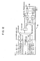
- FIG. 12 shows in block diagram a modification to the signal light outputting apparatus of the first embodiment of the present invention.
- the signal light outputting apparatus 7A shown in FIG. 12 adjusts, when to output a plurality of signal lights ⁇ 1 to ⁇ n of different wavelengths, the powers of the signal lights ⁇ 1 to ⁇ n so that they may be equal to values set in advance therefor and outputs the signal lights ⁇ 1 to ⁇ n of the adjusted powers.
- the signal light outputting apparatus 7A is used as a transmission apparatus for a terminal station which outputs signal light.
- the signal light outputting apparatus 7A includes signal light outputting units 15-1 to 15-n, a coupler 16, a separator or beam splitter 30, photodiodes (PD) 31-1 to 31-n, and a controller 32.
- the signal light outputting apparatus 7A further includes a 10:1 coupler 17.
- a route along which signal light passes is indicated by a thick line
- a route along which an electric signal passes is indicated by a thin line.
- the separator 30 extracts part of signal light combined by the coupler 16 via the coupler 17 and separates or demultiplexes the combined signal light for wavelengths corresponding to the signal light waves of the laser diodes 11-1 to 11-n of the signal light outputting units 15-1 to 15-n.
- the separator 30 extracts part of combined signal light and separates it into the individual signal lights ⁇ 1 to ⁇ n .
- the photodiodes (PD) 31-1 to 31-n are photo-electric converters which receive the signal lights ⁇ 1 to ⁇ n separated by the separator 30 and output electric signals corresponding to the signal light powers of the signal lights ⁇ 1 to ⁇ n .
- the function as a signal light power detection section for detecting the powers of the signal lights ⁇ 1 to ⁇ n of combined signal light and monitoring the signal light components of the combined signal light is realized by the separator 30 and the photodiodes 31-1 to 31-n described above.
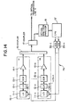
- the controller 32 includes control circuits 32-1 to 32-n to which electric signals obtained by photo-electric conversion by the photodiodes 31-1 to 31-n are inputted, respectively.
- each reference to the operational amplifier 34a that is, an initial value for the power of each signal light
- adjustment of each reference to the operational amplifier 34a is performed by transmitting a signal light upon initialization of the signal light outputting apparatus 7A and adjusting the power of the signal light so that the S/N ratios of the signals at the input end to an optical transmission line 5 may be equal to each other.
- control circuit 32-i shown in FIG. 13 if a predetermined voltage from the variable voltage source 34d is inputted as a reference voltage to the non-negated input terminal of the operational amplifier 34a and an electric signal representative of the power of a signal light separated from the photodiode 31-n is inputted to the negated input terminal of the operational amplifier 34a, then a voltage signal as a control signal for controlling the power of the signal light is outputted from the operational amplifier 34a.
- the voltage signal outputted from the control circuit 32-i in this manner is inputted to the post-amplifier 14-i of a signal light outputting unit 15-i.
- the voltage signal outputted from the control circuit 32-i is inputted to the transistor 14f so that control of the signal light output of the post-amplifier 14-i is performed in a similar manner as described hereinabove in connection with the first embodiment.
- control circuits 32-1 to 32-n of the controller 32 function as a signal light output controller for controlling, in order to control the powers of the signal lights ⁇ 1 to ⁇ n of the combined signal light, the signal light outputs of the corresponding post-amplifiers 14-1 to 14-n in response to the powers of the signal lights ⁇ 1 to ⁇ n detected by the signal light power detection section formed from the separator 30 and the photodiodes 31-1 to 31-n.
- control circuits 32-1 to 32-n have a function as a signal light power comparison and discrimination section for comparing the powers of the signal lights ⁇ 1 to ⁇ n detected by the photodiodes 31-1 to 31-n with the powers of the signal lights ⁇ 1 to ⁇ n set by the pre-emphasis to discriminate whether or not the values of the powers of the signal lights ⁇ 1 to ⁇ n detected by the photodiodes 31-1 to 31-n are equal to the values set by the pre-emphasis, and control the signal light outputs of the corresponding post-amplifiers 14-1 to 14-n in response to results of the comparison and discrimination.
- the output powers of the signal lights of the post-amplifiers 14-1 to 14-n are approximately +10 dBm
- the input powers of the signal lights to the photodiodes 31-1 to 31-n after the signal lights pass through the coupler 16, coupler 17 and separator 30 are approximately -10 dBm.
- the signal light outputting apparatus 7A similarly as in the signal light outputting apparatus 7 of the first embodiment, when signal lights ⁇ 1 to ⁇ n of different wavelengths are outputted from the signal light outputting units 15-1 to 15-n, respectively, the plurality of signal lights ⁇ 1 to ⁇ n thus outputted are combined by the coupler 16 and outputted to an optical transmission line 5.
- part of the signal light combined by the coupler 16 is inputted to the separator 30 via the coupler 17.
- the inputted light is separated into the individual signal lights by the separator 30, and the thus separated signal lights ⁇ 1 to ⁇ n are received by the photodiodes 31-1 to 31-n, by which they are converted into electric signals corresponding to the signal light powers thereof, respectively.
- the electric signals obtained by the photo-electric conversion by the photodiodes 31-1 to 31-n are inputted to the control circuits 32-1 to 32-n, respectively. Consequently, the control circuits 32-1 to 32-n control the signal light outputs of the post-amplifiers 14-1 to 14-n in response to the powers of the signal lights ⁇ 1 to ⁇ n detected by the photodiodes 31-1 to 31-n in order to control the powers of the corresponding signal lights ⁇ 1 to ⁇ n of the combined signal light.
- the signal light outputting apparatus 7A branches and extracts, when a plurality of signal lights ⁇ 1 to ⁇ n of different wavelengths are combined and outputted, part of the combined signal light of the signal lights ⁇ 1 to ⁇ n at the input end to the optical transmission line 5, and monitors the powers of the signal lights ⁇ 1 to ⁇ n by means of the separator 30, photodiodes 31-1 to 31-n and controller 32 and controls the signal light outputs of the post-amplifiers 14-1 to 14-n so that the powers of the signal lights ⁇ 1 to ⁇ n may always be equal to initially set values therefor. Consequently, similar advantages to those achieved by the signal light outputting apparatus 7 of the first embodiment are achieved by the modified signal light outputting apparatus 7A.
- the functions as a signal light power detection section for detecting the powers of the signal lights ⁇ 1 to ⁇ n of the combined signal light and monitoring the signal light components of the combined signal light are realized by the separator 30 and photodiodes 31-1 to 31-n, and the functions as a signal light output controller for controlling, in order to control the powers of the signal lights ⁇ 1 to ⁇ n of the combined signal light, the signal light outputs of the corresponding post-amplifiers 14-1 to 14-n in response to the powers of the signal lights ⁇ 1 to ⁇ n detected by the separator 30 and the photodiodes 31-1 to 31-n are realized by the controller 32. Consequently, the signal light outputting apparatus can be produced at a reduced cost
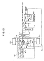
- FIG. 14 shows in block diagram another signal light outputting apparatus to which the present invention is applied.
- the signal light outputting apparatus 7B shown in FIG. 14 adjusts, when to output a plurality of signal lights ⁇ 1 to ⁇ n of different wavelengths, the wavelengths of signal lights ⁇ 1 to ⁇ n so that they may be equal to values set in advance therefor and outputs the signal lights ⁇ 1 to ⁇ n of the adjusted powers.
- the signal light outputting apparatus 7B is used as a transmission apparatus for a plurality of terminal stations (in FIG. 2, the A station 1 and the C station 3) which transmit and receive signal light therebetween in such a system as the optical transmission system 10 shown in FIG. 2 as described hereinabove.
- the signal light outputting apparatus 7B includes signal light outputting units 15-1 to 15-n, a coupler 16, an optical spectrum analyzer 18 and a CPU 19'.
- the signal light outputting apparatus 7B further includes a 10:1 coupler 17, and digital to analog converters (D/A) 35-1 to 35-n.
- each route along which signal light passes is indicated by a thick line, and a route along which an electric signal passes is indicated by a thin line.
- the optical spectrum analyzer 18 functions as a signal light wavelength detection section for detecting, from signal light combined by the coupler 16 and extracted partly by the coupler 17, wavelengths of the combined signal light for wavelengths corresponding to the signal light wavelengths of the laser diodes 11-1 to 11-n of the signal light outputting units 15-1 to 15-n.
- laser diode temperature adjustment members 36-1 to 36-n as light source temperature adjustment members for controlling the wavelengths of the output signal lights from the laser diodes 11-1 to 11-n by adjusting the temperatures in the proximity of the laser diodes 11-1 to 11-n are provided for the laser diodes 11-1 to 11-n, respectively. Details of the laser diode temperature adjustment members 36-1 to 36-n will be hereinafter described.
- the CPU 19' controls operation of the optical spectrum analyzer 18 and functions as a signal light wavelength controller for controlling, in order to control the wavelengths of the signal lights ⁇ 1 to ⁇ n of the combined signal light, the signal light wavelengths of the corresponding laser diodes 11-1 to 11-n in response to the wavelengths of the signal lights ⁇ 1 to ⁇ n detected by the optical spectrum analyzer 18.
- Control of the wavelengths of the output signal lights of the corresponding laser diodes 11-1 to 11-n in this instance is performed by controlling the temperatures of the laser diode temperature adjustment members 36-1 to 36-n provided for the corresponding laser diodes 11-1 to 11-n, respectively.
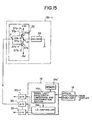
- the CPU 19' includes, as shown in FIG. 15, a memory 19a' for storing values of the wavelengths of the signal lights ⁇ 1 to ⁇ n , that is, initially set values of the wavelengths of the signal lights ⁇ 1 to ⁇ n , and realizes the functions corresponding to a signal light wavelength comparison and discrimination section 19d and a laser diode (LD) controller 19e by processing of software.
- a memory 19a' for storing values of the wavelengths of the signal lights ⁇ 1 to ⁇ n , that is, initially set values of the wavelengths of the signal lights ⁇ 1 to ⁇ n , and realizes the functions corresponding to a signal light wavelength comparison and discrimination section 19d and a laser diode (LD) controller 19e by processing of software.
- LD laser diode
- the signal light wavelength comparison and discrimination section 19d reads out the initially set values of the wavelengths of the signal lights corresponding to the inputted signal lights ⁇ 1 to ⁇ n from the memory 19a', and compares the wavelengths of the signal lights ⁇ 1 to ⁇ n detected by the optical spectrum analyzer 18 with the wavelengths of the signal lights ⁇ 1 to ⁇ n set in advance to discriminate whether or not the values of the wavelengths of the signal lights ⁇ 1 to ⁇ n detected by the optical spectrum analyzer 18 are equal to the respective preset values.
- the laser diode controller 19e outputs wavelength control signals for controlling the signal light wavelengths of the corresponding laser diodes 11-1 to 11-n in response to a result of the comparison and discrimination by the signal light wavelength comparison and discrimination section 19d.
- the wavelength control signals outputted from the laser diode controller 19e are converted from digital signals into analog signals of voltages corresponding to displacements between the wavelengths of the signal lights ⁇ 1 to ⁇ n detected by the optical spectrum analyzer 18 and the wavelengths of the signal lights ⁇ 1 to ⁇ n set in advance by means of the digital to analog converters 35-1 to 35-n.
- the digital to analog converters 35-1 to 35-n for example, if a detected wavelength is longer than a corresponding preset value, it is converted into a positive voltage, but if it is shorter than the corresponding preset value, it is converted into a negative voltage.
- the voltages thus obtained are inputted to the laser diode temperature adjustment members 36-1 to 36-n.
- the Peltier element 38 generates or absorbs heat depending upon the direction of electric current flowing therethrough so that the laser diode temperature adjustment member 36-i may have a desired temperature.
- the Peltier element operation circuit 37 is provided in a stage preceding the Peltier element 38 and flows electric current through the Peltier element 38 to operate the Peltier element 38.
- the Peltier element operation circuit 37 includes a pair of transistors 37a and 37b of different types connected in parallel to each other.
- the' base 37a-1 of the transistor 37a and the base 37b-1 of the transistor 37b are connected to each other.
- the junction between the base 37a-1 and the base 37b-1 is denoted at P.
- the emitter 37a-2 of the transistor 37a and the collector 37b-3 of the transistor 37b are connected to each other.
- the junction between the emitter 37a-2 and the collector 37b-3 is denoted at Q.
- a wavelength control signal (which will be hereinafter described) outputted from the CPU 19' is inputted to the junction P via a digital to analog converter 35-i, and the junction Q is connected to a terminal of the Peltier element 38.
- the other terminal of the Peltier element 38 is grounded, and a resistor may be interposed between the junction P and each of the digital to analog converters 35-1 to 35-n.
- the laser diode temperature adjustment member 36-i having the construction described above, when a wavelength control signal from the laser diode controller 19e of the CPU 19' is inputted via the digital to analog converter 35-i, one of the transistor 37a and the transistor 37b operates in response to the polarity (positive or negative) and the magnitude of the inputted voltage.
- the heat generation or absorption amount of the Peltier element 38 is varied in response to the direction and the magnitude of electric current flowing therethrough, and the temperature of the laser diode temperature adjustment member 36-i is controlled thereby.
- the temperatures of the laser diode temperature adjustment members 36-1 to 36-n-are controlled in this manner the temperatures in the proximity of the corresponding laser diodes 11-1 to 11-n are adjusted to control the wavelengths of the output signal lights from the laser diodes 11-1 to 11-n.
- part of the signal light combined by the coupler 16 is inputted via the coupler 17 to the optical spectrum analyzer 18, by which the wavelengths of the signal lights ⁇ 1 to ⁇ n of the combined signal light are detected from the inputted signal light.
- the CPU 19' controls, in order to control the wavelengths of the signal lights ⁇ 1 to ⁇ n of the combined signal light, the temperatures of the corresponding laser diode temperature adjustment members 36-1 to 36-n in response to the wavelengths of the signal lights ⁇ 1 to ⁇ n detected by the optical spectrum analyzer 18 thereby to control the signal light outputs from the laser diodes 11-1 to 11-n.
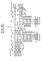
- a signal light which makes an object of control is represented by ⁇ m
- the CPU 19' resets m to 0 first in step B1 and then sets m to 1 so that the signal light which makes an object of control may be ⁇ 1 in step B2.
- the optical spectrum analyzer 18 monitors the signal light combined by the coupler 16 and extracted by the coupler 17 in step B3, and performs peak searching of the signal light ⁇ 1 in step B4.
- the optical spectrum analyzer 18 detects the signal light wavelength of the signal light ⁇ 1 and transmits the value of the detected wavelength of the signal light ⁇ 1 to the CPU 19' in response to a transmission request from the CPU 19' in step B5.
- the value of the wavelength of the signal light ⁇ 1 is within the range of ⁇ 0.1 nm both inclusive from the initially set value, then it is determined that the value of the detected wavelength of the signal light ⁇ 1 is equal to the initially set value, and control of the output of the signal light of the laser diode 11-1 which outputs the signal light ⁇ 1 is not performed (from the YES route of step B6 to step B10).
- the value of the wavelength of the signal light ⁇ 1 is not within the range of ⁇ 0.1 nm from the initially set value, it is subsequently discriminated whether or not the value of the detected wavelength of the signal light ⁇ 3 is within a range higher by more than 0.1 nm than the initially set value (from the NO route of step B6 to step B7).
- a wavelength control signal for decreasing the temperature of the laser diode 11-1 stepwise with a 1°C step is outputted to effect control of the wavelength of the signal light of the laser diode 11-1 which outputs the signal light ⁇ 1 (from the YES route of step B7 to step B8).
- a wavelength control signal for increasing the temperature of the laser diode 11-1 stepwise with a 1°C step is outputted to effect control of the wavelength of the signal light of the laser diode 11-1 which outputs the signal light ⁇ 1 (from the NO route of step B7 to step B9).
- the CPU 19' controls the signal light wavelengths of the laser diodes 11-1 to 11-n so that the values of the wavelengths of the signal lights ⁇ 1 to ⁇ n may always be equal to the initially set values. Consequently, otherwise possible variation in wavelength of the signal lights ⁇ 1 to ⁇ n can be prevented with certainty.
- control of the wavelength of signal light as is performed in the present embodiment using the CPU 19' cannot be performed, for example, using such control circuits 32-1 to 32-n as are employed in the modification to the first embodiment described hereinabove with reference to FIGS. 12 and 13.
- the signal light separated in this manner is photo-electrically converted by a corresponding one of the photodiodes 31-1 to 31-n, then since it can be detected that the power of the signal light has decreased, it can be recognized that the wavelength has varied. However, it cannot be recognized in what manner the wavelength has varied. Consequently, it cannot be discriminated in what manner the corresponding one of the laser diodes. 11-1 to 11-n should be controlled. Consequently, control in wavelength of signal light cannot be performed.
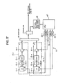
- FIG. 17 shows in block diagram a further signal light outputting apparatus to which the present invention is applied.
- the signal light outputting apparatus 7C shown in FIG. 17 adjusts, when to output a plurality of signal lights ⁇ 1 to ⁇ n of different wavelengths, the powers and the wavelengths of signal lights ⁇ 1 to ⁇ n so that they may be equal to respective values set in advance therefor and outputs the signal lights ⁇ 1 to ⁇ n of the adjusted powers and wavelengths.
- the signal light outputting apparatus 7C is used as a transmission apparatus for a plurality of terminal stations which transmit and receive signal light therebetween (in FIG. 2, the A station 1 and the C station 3) as described hereinabove.
- the signal light outputting apparatus 7C includes signal light outputting units 15-1 to 15-n, a coupler 16, an optical spectrum analyzer 18 and a CPU 19".
- the signal light outputting apparatus 7C further includes a 10:1 coupler 17, and digital to analog converters 20-1 to 20-n and 35-1 to 35-n.
- each route along which signal light passes is indicated by a thick line, and a route along which an electric signal passes is indicated by a thin line.
- laser diode temperature adjustment members 36-1 to 36-n each formed from a Peltier element are provided for the laser diodes 11-1 to 11-n of the signal light outputting units 15-1 to 15-n, respectively.
- the optical spectrum analyzer 18 functions as a signal light power and wavelength detection section for detecting, from signal light combined by the coupler 16 and extracted partly by the coupler 17, the powers and wavelengths of the combined signal light for wavelengths corresponding to the signal light wavelengths of the laser diodes 11-1 to 11-n of the signal light outputting units 15-1 to 15-n.
- the CPU 19 controls operation of the optical spectrum analyzer 18 and functions as a signal light output controller for controlling, in order to control the powers and the wavelengths of the signal lights ⁇ 1 to ⁇ n of the combined signal light, the signal light outputs of the corresponding post-amplifiers 14-1 to 14-n in response to the powers and the wavelengths of the signal lights ⁇ 1 to ⁇ n detected by the optical spectrum analyzer 18.
- the CPU 19" functions also as a signal light wavelength controller for controlling the signal light wavelengths of the corresponding laser diodes 11-1 to 11-n.
- Control of the wavelengths of the output signal lights of the corresponding laser diodes 11-1 to 11-n then is performed by controlling the temperatures of the laser diode temperature adjustment members 36-1 to 36-n provided for the corresponding laser diodes 11-1 to 11-n.
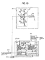
- the CPU 19" includes, as shown in FIGS. 18 and 19, a memory 19a" for storing values of the powers and wavelengths of the signal lights ⁇ 1 to ⁇ n , that is, initially set values for the powers and the wavelengths of the signal lights ⁇ 1 to ⁇ n , and realizes the functions corresponding to a signal light power comparison and discrimination section 19b, a post-amplification control section 19c, a signal light wavelength comparison and discrimination section 19d and a laser diode controller 19e by processing of software.
- the signal light power comparison and discrimination section 19b reads out the initially set values of the the powers of the signal lights corresponding to the inputted signal lights ⁇ 1 to ⁇ n from the memory 19a", and compares the powers of the signal lights ⁇ 1 to ⁇ n detected by the optical spectrum analyzer 18 with the powers of the signal lights ⁇ 1 to ⁇ n set by the pre-emphasis described hereinabove to discriminate whether or not the values of the powers of the signal lights ⁇ 1 to ⁇ n detected by the optical spectrum analyzer 18 are equal to the values set by the pre-emphasis.
- the post-amplification control section 19c outputs output control signals for controlling the signal light outputs of the post-amplifiers 14-1 to 14-n in response to results of the comparison and discrimination by the signal light power comparison and discrimination section 19b.
- output control signals outputted from the post-amplification control section 19c are converted from digital signals into analog signals by the digital to analog converters 20-1 to 20-n and then inputted to the post-amplifiers 14-1 to 14-n.
- the signal light wavelength comparison and discrimination section 19d reads out the initially set values of the the wavelengths of the signal lights corresponding to the inputted signal lights ⁇ 1 to ⁇ n from the memory 19a", and compares the wavelengths of the signal lights ⁇ 1 to ⁇ n detected by the optical spectrum analyzer 18 with the wavelengths of the signal lights ⁇ 1 to ⁇ n set in advance to discriminate whether or not the values of the wavelengths of the signal lights ⁇ 1 to ⁇ n detected by the optical spectrum analyzer 18 are equal to the values set in advance.
- the laser diode controller 19e outputs, in response to a result of the comparison and discrimination by the signal light wavelength comparison and discrimination section 19d, wavelength control signals for controlling the corresponding signal light wavelengths of the laser diodes 11-1 to 11-n.
- the wavelength control signals outputted from the laser diode controller 19e are converted from digital signals into analog signals of voltages corresponding to displacements between the wavelengths of the signal lights ⁇ 1 to ⁇ n detected by the optical spectrum analyzer 18 and the wavelengths of the signal lights ⁇ 1 to ⁇ n set in advance by the digital to analog converters 35-1 to 35-n, respectively.
- the digital to analog converters 35-1 to 35-n respectively.
- a detected wavelength is longer than a corresponding preset value, then it is converted into a positive voltage, but if it is shorter than the corresponding preset value, then it is converted into a negative voltage.
- the voltages thus obtained are inputted to the laser diode temperature adjustment members 36-1 to 36-n.
- the signal light outputting apparatus 7C of the present embodiment having the construction described above, when signal lights ⁇ 1 to ⁇ n of different wavelengths are outputted from the signal light outputting units 15-1 to 15-n, respectively, the plurality of signal lights ⁇ 1 to ⁇ n thus outputted are combined by the coupler 16 and outputted to an optical transmission line 5.
- part of the signal light combined by the coupler 16 is inputted via the coupler 17 to the optical spectrum analyzer 18, by which the powers and the wavelengths of the signal lights ⁇ 1 to ⁇ n of the combined signal light are detected from the inputted signal light.
- the CPU 19" controls, in order to control the powers of the corresponding signal lights ⁇ 1 to ⁇ n of the combined signal light, the signal light outputs of the post-amplifiers 14-1 to 14-n in response to the powers of the signal lights ⁇ 1 to ⁇ n detected by the optical spectrum analyzer 18. It is to be noted that the optical spectrum analyzer 18 and the CPU 19" operate, for example, in such a manner as described hereinabove with reference to the flow chart of FIG. 5.
- the CPU 19 controls, in order to control the wavelengths of the signal lights ⁇ 1 to ⁇ n of the combined signal light, the temperatures of the corresponding laser diode temperature adjustment members 36-1 to 36-n in response to the wavelengths of the signal lights ⁇ 1 to ⁇ n detected by the optical spectrum analyzer 18 thereby to control the signal light outputs from the laser diodes 11-1 to 11-n.
- the optical spectrum analyzer 18 and the CPU 19" then operate, for example, in such a manner as described hereinabove with reference to the flow chart of FIG. 16.
- control of the powers of the signal lights ⁇ 1 to ⁇ n and the control of the wavelengths of the signal lights ⁇ 1 to ⁇ n described above may be performed simultaneously with each other, or the control of the wavelengths (or powers) of the signal lights ⁇ 1 to ⁇ n may be performed after the control of the powers (or wavelengths) of the signal lights ⁇ 1 to ⁇ n is performed.
- the signal light outputting apparatus 7C of the present embodiment when a plurality of signal lights ⁇ 1 to ⁇ n of different wavelengths are combined and outputted, part of signal light obtained by the combination of the signal lights ⁇ 1 to ⁇ n is branched and extracted at an input end to an optical transmission line 5, and the powers and the wavelengths of the signal lights ⁇ 1 to ⁇ n are monitored by the optical spectrum analyzer 18.
- the CPU 19 controls the signal light outputs of the laser diodes 11-1 to 11-n so that the values of the wavelengths of the signal lights ⁇ 1 to ⁇ n may always be equal to the respective initially set values. Consequently, otherwise possible variation in wavelength of the signal lights ⁇ 1 to ⁇ n can be prevented while controlling the ratios of the powers of the signal lights ⁇ 1 to ⁇ n set by the pre-emphasis with certainty.
- the powers of the signal lights ⁇ 1 to ⁇ n are controlled by controlling the signal light outputs of the post-amplifiers 14-1 to 14-n, otherwise possible variation in wavelength of signal light which arises when the output of a signal light source (laser diode) is controlled in such an apparatus as the ordinary signal light outputting apparatus described hereinabove can be prevented, and control of the wavelengths of the signal lights ⁇ 1 to ⁇ n described above can be achieved readily.
- pre-emphasis of the signal light outputting apparatus 7 when signal light is outputted can be stabilized over a long period of time to suppress an otherwise possible dispersion in branching and insertion characteristic between different signal lights to a minimum level.
- otherwise possible variation in branching and insertion characteristic of the light branching and insertion apparatus 4 which is caused by variation in wavelength. of signal light can be prevented to allow transmission and reception of signal light to be performed accurately between the terminal stations 1 to 3.
- control of the powers of the signal lights ⁇ 1 to ⁇ n is performed by the control circuits 32-1 to 32-n
- analog to digital converters which are controlled by a CPU may alternatively be provided in a stage following the photodiodes 31-1 to 31-n.
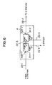
- the light branching and insertion apparatus 4 is Provided a tn the branching points of the optical transmission lines 5 which connect the plurality of terminal stations 1 to 3 as described hereinabove and outputs signal light of a desired wavelength inputted from any of the terminal stations 1 to 3 to another desired one of the terminal stations 1 to 3 to allow transmission of the signal light between the desired ones of the terminal stations.
- the light branching and insertion apparatus 4 includes a branching element 21-1 and an insertion element 21-2.
- the branching element 21-1 When signal light is inputted from an input side optical fiber 22-1, the branching element 21-1 outputs a signal light of a desired wavelength from within the inputted signal light to the insertion element 21-2 via another optical fiber 22-3, but outputs signal lights of the other wavelengths than the desired wavelength from within the inputted signal light to a branching output side optical fiber 22-4.
- the branching element 21-1 is formed from a dielectric multilayer film filter which functions, as seen from FIG. 7(a), for the signal light of the desired wavelength from within the signal light inputted thereto from the input side optical fiber 22-1 through a port 1, a band-pass filter which outputs the signal light of the desired wavelength to the optical fiber 22-3 through another port 2, but functions, for the signal lights of the other wavelengths than the desired wavelength from within the signal light inputted thereto from the input side optical fiber 22-1 through the port 1, as a band block filter (notch filter) which outputs the signal lights of the other wavelengths to the branching output side optical fiber 22-4 through a further port 3.
- a dielectric multilayer film filter which functions, as seen from FIG. 7(a), for the signal light of the desired wavelength from within the signal light inputted thereto from the input side optical fiber 22-1 through a port 1, a band-pass filter which outputs the signal light of the desired wavelength to the optical fiber 22-3 through another port 2, but functions, for the signal lights of the other wavelengths than the desired wavelength from
- the insertion element 21-2 combines signal light inputted thereto from a branching input side optical fiber 22-5 with signal light inputted thereto from the branching element 21-1 via the optical fiber 22-3 and outputs the thus combined signal light to an output side optical fiber 22-2.
- the insertion element 21-2 is formed from a dielectric multilayer film filter which functions, as seen from FIG. 7(b), for the signal light inputted thereto from the optical fiber 22-3 through the port 2, a band-pass filter which outputs the signal light to the output side optical fiber 22-2 through the port 1, but functions, for the signal light inputted thereto from the branching input side optical fiber 22-5 through the port 3, as a band block filter (notch filter) which outputs the signal light to the output side optical fiber 22-2 through the port 1.
- a dielectric multilayer film filter which functions, as seen from FIG. 7(b), for the signal light inputted thereto from the optical fiber 22-3 through the port 2, a band-pass filter which outputs the signal light to the output side optical fiber 22-2 through the port 1, but functions, for the signal light inputted thereto from the branching input side optical fiber 22-5 through the port 3, as a band block filter (notch filter) which outputs the signal light to the output side optical fiber 22-2 through the port 1.
- the insertion element 21-2 functions as an optical coupler which combines signal light inputted thereto from the port 2 and signal light inputted thereto from the port 3 with each other and outputs the combined signal light to the port 1.
- the branching element 21-1 and the insertion element 21-2 can be formed from dielectric multilayer filters of a same type.
- the light branching and insertion apparatus 4 is formed using a dielectric multilayer film filter in this manner, it can branch a plurality of signal lights of different wavelengths transmitted by a single optical fiber depending upon the wavelength or insert a signal light of a desired wavelength into a plurality of signal lights of different wavelengths transmitted by a single optical fiber.
- the optical transmission lines 107 are constructed such that they overlap with each other between different terminal stations, with the light branching and insertion apparatus 4 shown in FIG. 6, the optical transmission lines 5 can be formed simply without causing them overlapping with each other as seen in FIG. 2.
- Each of the dielectric multilayer film filters is formed as such a 3-port type optical 1 filter as shown in FIG. 7(a) or 7(b).
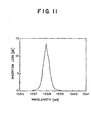
- the dielectric multilayer film filter shown in FIG. 7(a) has, between the port 1 and the port 2 thereof, such a wavelength characteristic of a band-pass filter having a center wavelength of 1,558 nm as shown in FIG. 10, but has, between the port 1 and the port 3 thereof, a wavelength characteristic of a band block filter having a center wavelength of 1,558 nm as shown in FIG. 11.
- FIGS. 10 and 11 illustrates a relationship between the wavelength of signal light and the insertion loss of signal light at the wavelength.
- While such branching and insertion of signal light can be performed also by means of an optical coupler, since the optical coupler exhibits a high loss when it effects branching and insertion of signal light, if a light branching and insertion apparatus is constructed using this optical coupler, then also the loss of signal light transmitted via the light branching and insertion apparatus exhibits a high loss.
- the light branching and insertion apparatus 4 is formed using dielectric multilayer film filters which exhibit a loss of signal light lower than optical couplers so that the loss of signal light transmitted via the light branching and insertion apparatus 4 may be low.
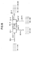
- each of the dielectric multilayer film filters is composed of lenses 24-1 to 24-3 and a dielectric multilayer film 25.
- reference numeral 26 denotes an optical fiber.
- the lenses 24-1 to 24-3 are collimate lenses individually attached to the optical fibers 26 in order to assure high convergency of signal light.
- the dielectric multilayer film 25 actually has a function as a band-pass filter which passes signal light therethrough or another function as a band block filter which reflects signal light depending upon the wavelength of signal light inputted thereto.
- the dielectric multilayer film filter 23 is used for the insertion element 21-2, signal light is inputted through the port 2 and signal light to be inserted is inputted through the port 3, and the combined signal light of the inputted signal light and the signal light to be inserted is outputted through the port I.
- the branching element 21-1 outputs the signal lights ⁇ A2 to ⁇ A5 from the port 2 thereof to the optical fiber 22-3, but branches the signal lights ⁇ A1 and ⁇ A6 and outputs them from the port 3 thereof to the branching output side optical fiber 22-4.
- the insertion element 21-2 combines the signal lights ⁇ A2 to ⁇ A5 and the signal lights ⁇ B1 and ⁇ B6 with each other and outputs them from the port 1 thereof to the output side optical fiber 22-2.
- Branching and insertion of signal light by the dielectric multilayer film filter 23 are performed in this manner.
- the light branching and insertion apparatus 4 shown in FIG. 6 which has the construction described above, if signal light is inputted from the input side optical fiber 22-1, then the light branching and insertion apparatus 4 outputs a signal light of a desired wavelength from within the inputted signal light to the output side optical fiber 22-2 via the optical fiber 22-3 and the insertion element 21-2, but outputs signal lights of the other wavelengths than the desired wavelength from within the inputted signal light to the branching output side optical fiber 22-4.
- the light branching and insertion apparatus 4 outputs signal light inputted thereto from the branching input side optical fiber 22-5 to the output side optical fiber 22-2.
- the light branching and insertion apparatus 4 shown in FIG. 6 can effect branching and insertion of signal light upon transmission of the signal light with a low loss and with a high degree of accuracy while it has a simple construction that it includes the branching element 21-1 and the insertion element 21-2 each formed from a dielectric multilayer film filter.
- the light branching and insertion apparatus 4 since a dielectric multilayer film filter which is an optical filter of the passive type is employed, branching and insertion of signal light can be effect without application of any voltage, and the light branching and insertion apparatus 4 can operate stably also, for example, in an optical transmission system which effects submarine optical communication.
- the reception apparatus 8 is provided in each of the B station 2 and the C station 3 as described above.
- the reception apparatus 8 receives signal light transmitted thereto from the transmission apparatus 7 of any other terminal station and demodulates the received signal light.
- a reception apparatus of the type which includes, for example, an optical demultiplexing element having a filtering function, and a plurality of signal light reception units for performing demodulation processing for a plurality of signal lights outputted from the optical demultiplexing element.
Landscapes
- Engineering & Computer Science (AREA)
- Computer Networks & Wireless Communication (AREA)
- Signal Processing (AREA)
- Physics & Mathematics (AREA)
- Electromagnetism (AREA)
- Optical Communication System (AREA)
- Lasers (AREA)
Claims (12)
- Eine Signallichtausgabevorrichtung, gekennzeichnet durch:eine Vielzahl von Signallichtausgabeeinheiten (15-i), eine jede mit einer Signallichtquelle (11-i) zur Ausgabe eines-Signallichts mit einer jeweiligen Wellenlänge, und einem optischen Verstärker (14-i) zur Verstärkung des von der Signallichtquelle (11-i) ausgegebenen Signallichts;einen optischen Combiner (16) zum Zusammenführen einer Vielzahl von Signallichten unterschiedlicher Wellenlängen, ausgegeben von den Signallichtausgabeeinheiten (15-i);einen Signallichtenergiedetektor (18) zum Extrahieren eines Teils des durch den optischen Combiner (16) zusammengeführten Signallichts, um Energien des Signallichts für individuelle Wellenlängen entsprechend den Signallichtwellen der Signallichtquellen (11-i) zu erfassen; undeinen Signallichtausgäbecontroller (19; 32; 19") zur Steuerung der optischen Verstärker (14-i) in Reaktion auf die Energien der durch den Signallichtenergiedetektor (18) erfassten Signallichte mit den individuellen Wellenlängen, um dadurch die Energie des von einem jeden der Vielzahl von optischen Verstärkern ausgegebenen Signallichts zu steuern, und die Energien der durch den optischen Combiner (16) zusammengeführten Signallichte.
- Eine Signallichtausgabevorrichtung nach Anspruch 1,
wobei der Signallichtausgabecontroller (19; 19") einen Signallichtenergievergleichs- und Unterscheidungsabschnitt (19b) umfasst, zum Vergleich der Energien der durch den Signallichtenergiedetektor (18) erfassten Signallichte mit den individuellen Wellenlängen, mit voreingestellten (19a, 19a") Energien der Signallichte der individuellen Wellenlängen, um zu unterscheiden, ob oder ob nicht die Energien der durch den Signallichtenergiedetektor (18) erfassten Signallichte mit individuellen Längenlängen gleich den voreingestellten Energien der Signallichte mit den individuellen Wellenlängen sind, und zur Steuerung (19c) der Signallichtausgaben der entsprechenden optischen Verstärker (14-i) zur Verstärkung der Signallichte mit den Wellenlängen in Reaktion auf die Vergleichs- und Unterscheidungsergebnisse von dem Signallichtenergievergleichs- und Unterscheidungsabschnitt (19b). - Eine Signall'ichtausgabevorrichtung nach Anspruch 1,
wobei der Signallichtenergiedetektor (18) einen optischen Spektrum-Analysator umfasst. - Eine Signallichtausgabevorrichtung nach Anspruch 1,
wobei der Signallichtenergiedetektor (18) einen optischen Separator (30) umfasst, zur Extraktion eines Teils des durch den optischen Combiner (16) zusammengeführten Signallichts, und zur Separierung des extrahierten Signallichts in Signallichte mit individuellen Wellenlängen entsprechend den Signallichtwellenlängen der Signallichtquellen (11-i), und einen photoelektrischen Wandler (31-i) zur Wandlung der durch den optischen Separator (30) separierten Signallichte in elektrische Signale. - Eine Signallichtausgabevorrichtung nach Anspruch 1, und einen Signallichtwellenlängendetektor (18) umfassend, zur Extraktion eines Teils des durch den optischen Combiner (16) zusammengeführten Signallichts, um Wellenlängen des Signallichts für individuelle Wellenlängen entsprechend den Signallichtwellenlängen der Signallichtquellen (11-i) zu erfassen; und wobei
der Signallichtausgabecontroller (19") auch die Signallichtquellen (11-i) steuert; in Reaktion auf die Wellenlängen der durch den Signallichtwellenlängendetektor (18) erfassten Signallichte, um dadurch die von jeder der Signallichtquellen ausgegebene Wellenlänge zu steuern, und die Wellenlängen der durch den optischen Combiner (16) zusammengeführten Signallichte. - Eine Signallichtausgabevorrichtung nach Anspruch 5,
wobei der Signallichtausgabecontroller (19") einen Signallichtwellenlängenvergleichs- und Unterscheidungsabschnitt (19d) umfasst, zum Vergleich der durch den Signallichtwellenlängendetektor (18) erfassten Signallichtwellenlängen der individuellen Signallichtquellen (11-i), mit voreingestellten (19a") Signallichtwellenlängen der individuellen Signallichtquellen, um festzustellen, ob oder ob nicht die durch den Signallichtwellenlängendetektor (18) erfassten Signallichtwellenlängen der individuellen Signallichtquellen (11-i), gleich den voreingestellten Signallichtwellenlängen der individuellen Signallichtquellen (11-i) sind, und zur Steuerung (19e) der Signallichtwellenlängen der entsprechenden Signallichtquellen (11-i) zur Ausgabe der Signallichte der Wellenlängen in Reaktion auf Vergleichs- und Unterscheidungsergebnisse durch den Signallichtwellenlängenvergleichs- und Unterscheidungsabschnitt (19d). - Eine Signallichtausgabevorrichtung nach Anspruch 5, weiter mit einem für jede der Signallichtquellen (11-i) bereitgestellten Lichtquellentemperatureinstellelement (36-i), und wobei der Signallichtausgabecontroller (19") die für die individuellen Signallichtquellen (11-i) bereitgestellten Lichtquellentemperatureinstellelemente (36-i) steuert, um die Signallichtwellenlängen der entsprechenden Signallichtquellen (11-i) für eine Ausgabe der Signallichte mit den Wellenlängen zu steuern.
- Eine Signallichtausgabevorrichtung nach Anspruch 5, wobei der Signallichtwellenlängendetektor (18) einen optischen Spektrum-Analysator umfasst.
- Eine Signallichtausgabevorrichtung nach Anspruch 6, wobei der Signallichtausgabecontroller (19") einen Signallichtenergievergleichs- und Unterscheidungsabschnitt (19b) umfasst, um die Energien der durch das Signallichterfassungselement (18) erfassten Signallichte der individuellen Wellenlängen mit voreingestellten (19a") Energien der Signallichte der individuellen Wellenlängen zu vergleichen, um festzustellen, ob oder ob nicht die Energien der durch das Signallichterfassungselement (18) erfassten Signallichte der individuellen Wellenlängen gleich den voreingestellten Energien der Signallichte der individuellen Wellenlängen sind, und zur Steuerung (19c) der Signalausgaben der entsprechenden optischen Verstärker für eine Verstärkung der Signallichte mit den Wellenlängen in Reaktion auf die Vergleichs- und Unterscheidungsergebnisse des Signallichtenergievergleichs- und Unterscheidungsabschnitts (19b).
- Eine Signallichtausgabevorrichtung nach Anspruch 7,
wobei eine jedes der Lichtquellentemperatureinstellelemente (36-i) ein Peltier-Element (38) umfasst. - Ein optisches Übertragungssystem mit einer Signallichtausgabevorrichtung, gekennzeichnet durch:wobei das Signallicht zwischen der Vielzahl von Signallichtausgabevorrichtungen (7C) über die Lichtverzweige- und/oder Einfügevorrichtung (4) kommuniziert wird.eine Vielzahl von Signallichtausgabevorrichtungen (7C), jede mit einer Vielzahl von Signallichtausgabeeinheiten (15-i), jede mit einer Signallichtquelle (11-i) zur Ausgabe eines Signallichts mit einer jeweiligen Wellenlänge, und einem optischen Verstärker (14-i) zur Verstärkung des von der Signallichtquelle (11-i) ausgegebenen Signallichts;einen optischen Combiner (16) zur Zusammenführung einer Vielzahl von Signallichten unterschiedlicher Wellenlängen, ausgegeben von den Signallichtausgabeeinheiten (15-i);ein Signallichterfassungselement (18) zur Extraktion eines Teils des durch den optischen Combiner (16) zusammengeführten Signallichts, um Energien und Wellenlängen des Signallichts für die individuellen Wellenlängen entsprechend den Signallichtwellenlängen der Signallichtquellen (11-i) zu erfassen;einen Signallichtausgabecontroller (19", 19a", 19b, 19c, 19d, 19e) zur Steuerung (a) der optischen Verstärker (14-i) in Reaktion auf die Energien des durch das Signallichterfassungselement (18) erfassten Signallichts mit den individuellen Wellenlängen, um dadurch den Energieinhalt des von einem jeden der Vielzahl von optischen Verstärkern ausgegebenen Signallichts zu steuern, und die Energien der durch den optischen Combiner (16) zusammengeführten Signallichte, und (b) der Signallichtquellen (11-i) in Reaktion auf die Wellenlängen der durch das Signallichterfassungselement 18 erfassten Signallichts, um dadurch die ausgegebene Wellenlänge einer jeden der Signallichtquellen und die Wellenlängen der durch den optischen Combiner (16) zusammengeführten Signallichte zu steuern;ein optisches Fasersystem (5) zur gegenseitigen Verbindung der Vielzahl von Signallichtausgabevorrichtungen (7C); undeine Lichtverzweige- und/oder Einfügevorrichtung (4), an einem Verzweigungspunkt des optischen Fasersystems (5) bereitgestellt, mit dem die Vielzahl von Signallichtausgabevorrichtungen (7C) miteinander verbunden ist, wobei die Lichtverzweige- und Einfügevorrichtung (4) ein Verzweigungselement (21-1) umfasst, zur Ausgabe eines Signallichts mit einer ausgewählten Wellenlänge aus dem von einer eingangsseitigen optischen Faser (22-1) an die Lichtverzweige- und/oder Einfügevorrichtung (4) eingegebenen Signallicht, zu einer ausgangsseitigen optischen Faser (22-3) und zur Ausgabe von Signallichten mit Wellenlängen, die sich von der ausgewählten Wellenlänge unterscheiden, aus dem von der eingangsseitigen optischen Faser (22-1) an die Lichtverzweigungs- und/oder Einfügevorrichtung (4) eingegebenen Signallicht, zu einer verzweigungsausgangsseitigen optischen Faser (22-4), und ein Einfügeelement (22-1) zur Ausgabe von Signallicht, eingegeben dorthin von einer verzweigungseingangsseitigen optischen Faser (22-5), zu einer ausgangsseitigen optischen Faser (22-2);
- Ein optisches Übertragungssystem mit einer Signallichtausgabevorrichtung nach Anspruch 11, dadurch gekennzeichnet, dass der Signallichtausgabecontroller die Signallichtwellenlängen der entsprechenden Signallichtquellen steuert, durch ein Steuern von Temperaturen der Lichtquellentemperatureinstellelemente, jeweilig bereitgestellt für die entsprechenden Signallichtquellen.
Applications Claiming Priority (3)
| Application Number | Priority Date | Filing Date | Title |
|---|---|---|---|
| JP17961696A JP4405598B2 (ja) | 1996-07-09 | 1996-07-09 | 信号光出力装置及び信号光出力装置を有する光伝送システム |
| JP179616/96 | 1996-07-09 | ||
| JP17961696 | 1996-07-09 |
Publications (3)
| Publication Number | Publication Date |
|---|---|
| EP0818894A2 EP0818894A2 (de) | 1998-01-14 |
| EP0818894A3 EP0818894A3 (de) | 2002-04-24 |
| EP0818894B1 true EP0818894B1 (de) | 2004-02-25 |
Family
ID=16068875
Family Applications (1)
| Application Number | Title | Priority Date | Filing Date |
|---|---|---|---|
| EP97111163A Expired - Lifetime EP0818894B1 (de) | 1996-07-09 | 1997-07-03 | Sender für optische Signale und optisches Übertragunssystem mit einem solchen Sender |
Country Status (5)
| Country | Link |
|---|---|
| US (1) | US6204945B1 (de) |
| EP (1) | EP0818894B1 (de) |
| JP (1) | JP4405598B2 (de) |
| CN (1) | CN1124000C (de) |
| DE (1) | DE69727730T2 (de) |
Families Citing this family (44)
| Publication number | Priority date | Publication date | Assignee | Title |
|---|---|---|---|---|
| JPH1075005A (ja) * | 1996-08-30 | 1998-03-17 | Ando Electric Co Ltd | 光周波数多重通信用光源装置 |
| DE19734957C1 (de) * | 1997-08-13 | 1998-12-24 | Lucent Tech Network Sys Gmbh | Verfahren und Anordnung zur Wellenlängenstabilisierung für mehrkanalige optische Übertragungssysteme |
| US6496288B2 (en) * | 1997-10-17 | 2002-12-17 | Fujitsu Limited | Wavelength multiplexing transmission apparatus and wavelength demultiplexing reception apparatus |
| JPH11243371A (ja) * | 1998-02-26 | 1999-09-07 | Fujitsu Ltd | 光伝送装置 |
| JPH11331127A (ja) * | 1998-05-19 | 1999-11-30 | Fujitsu Ltd | 波長分割多重システム、及びその端局 |
| US6317231B1 (en) * | 1998-09-04 | 2001-11-13 | Lucent Technologies Inc. | Optical monitoring apparatus and method for network provisioning and maintenance |
| US6441940B1 (en) * | 1998-10-09 | 2002-08-27 | Agere Systems Guardian Corp. | Wavelength stabilization of light emitting components |
| JP2001044970A (ja) * | 1999-07-27 | 2001-02-16 | Nec Corp | 波長多重伝送装置 |
| JP3779502B2 (ja) * | 1999-08-12 | 2006-05-31 | 富士通株式会社 | 光増幅装置、光送信装置、光伝送システム、光増幅方法および光入射方法 |
| US6369923B1 (en) * | 1999-09-07 | 2002-04-09 | Cinta Corporation | Multiwavelength stabilization with a single reference comb filter in DWDM systems |
| EP1220483A4 (de) | 2000-07-31 | 2005-09-07 | Mitsubishi Electric Corp | Vorrichtung zum optischen wellenlängen multiplex |
| WO2002025843A1 (en) * | 2000-09-21 | 2002-03-28 | Nokia Corporation | Method and system for transmitting a signal via a non-linear transmission unit |
| US6748179B2 (en) * | 2001-03-07 | 2004-06-08 | Harris Corporation | WDM channel monitoring system and method |
| US20040105136A1 (en) * | 2001-05-08 | 2004-06-03 | Corvis Corporation | Interconnections and protection between optical communications networks |
| US6556319B2 (en) * | 2001-05-08 | 2003-04-29 | Dorsal Networks, Inc. | Split redundant trunk architecture using passive splitters and path switching |
| WO2002099468A2 (en) * | 2001-06-01 | 2002-12-12 | Lightchip, Inc. | Device and method for monitoring optical signals with increased dynamic range |
| US7253897B2 (en) | 2001-06-01 | 2007-08-07 | Cidra Corporation | Optical spectrum analyzer |
| EP1393026A1 (de) * | 2001-06-01 | 2004-03-03 | CiDra Corporation | Optischer kanalüberwacher |
| US6603597B2 (en) | 2001-06-08 | 2003-08-05 | Photon-X, Inc. | Dual mode programmable optical logarithmic amplifier driver |
| AU2002357724A1 (en) | 2001-11-14 | 2003-05-26 | Massachusetts Institute Of Technology | Tunable optical add/drop multiplexer with multi-function optical amplifiers |
| US6970652B2 (en) * | 2001-12-07 | 2005-11-29 | Oplink Communications, Inc. | Auto-setting and optimization of EAM with optical line systems |
| US7239807B2 (en) * | 2002-02-07 | 2007-07-03 | Nortel Networks Limited | Variable clamp equalization method and apparatus |
| WO2004074805A1 (ja) * | 2003-02-18 | 2004-09-02 | Fujitsu Limited | 光源装置 |
| JP4594636B2 (ja) | 2004-03-23 | 2010-12-08 | 富士通株式会社 | 光伝送装置 |
| US8064770B2 (en) * | 2004-08-11 | 2011-11-22 | Tyco Electronics Subsea Communications Llc | System and method for spectral loading an optical transmission system |
| US7171070B1 (en) | 2005-02-04 | 2007-01-30 | At&T Corp. | Arrangement for low cost path protection for optical communications networks |
| US7389018B1 (en) | 2005-02-04 | 2008-06-17 | At&T Corp. | Arrangement for low cost path protection for optical communications networks |
| JP4303710B2 (ja) * | 2005-07-15 | 2009-07-29 | 富士通株式会社 | 光伝送装置 |
| JP5076660B2 (ja) * | 2007-06-11 | 2012-11-21 | 日本電気株式会社 | 波長多重伝送装置、制御方法及び制御プログラム |
| US8582976B2 (en) * | 2007-10-03 | 2013-11-12 | British Telecommunications Public Limited Company | Transmission of broadband signals |
| CN101141222B (zh) * | 2007-10-16 | 2011-05-11 | 中兴通讯股份有限公司 | 一种实现光信号波形发生的装置及方法 |
| RU2518182C2 (ru) * | 2009-08-31 | 2014-06-10 | Хуавэй Текнолоджиз Ко., Лтд. | Способ и устройство обнаружения внутриполосного оптического отношения сигнал-шум |
| JP5359760B2 (ja) * | 2009-10-09 | 2013-12-04 | 住友電気工業株式会社 | 光トランシーバ |
| CN102237932B (zh) * | 2010-04-30 | 2016-07-06 | 中兴通讯股份有限公司 | 长距光放大装置、无源光网络和光信号传输方法 |
| US8983306B2 (en) * | 2011-01-31 | 2015-03-17 | Alcatel Lucent | Spectral alignment of a WDM device to a specified frequency grid |
| JP5201254B2 (ja) * | 2011-10-27 | 2013-06-05 | 富士通株式会社 | 光増幅装置および光受信装置 |
| WO2015146105A1 (ja) * | 2014-03-27 | 2015-10-01 | 日本電気株式会社 | 光通信装置、光通信システム及び光送信方法 |
| US9577780B2 (en) * | 2014-06-26 | 2017-02-21 | Luxtera, Inc. | Method and system for a polarization immune wavelength division multiplexing demultiplexer |
| EP3175608B1 (de) | 2014-07-30 | 2020-12-23 | British Telecommunications public limited company | Verfahren und vorrichtung zur zuweisung von leistungsniveaus in einem digitalen teilnehmeranschlussnetzwerk |
| JP6648437B2 (ja) | 2015-07-29 | 2020-02-14 | 富士通株式会社 | 送受信システム、送信装置、受信装置及び送受信システムの制御方法 |
| JP6717082B2 (ja) * | 2016-06-30 | 2020-07-01 | 富士通オプティカルコンポーネンツ株式会社 | 光送信モジュールおよび光送信モジュールの制御方法 |
| CN110089052B (zh) | 2016-12-21 | 2022-02-08 | 英国电讯有限公司 | 网络节点和通信网络 |
| JP7452637B2 (ja) * | 2020-05-14 | 2024-03-19 | 日本電気株式会社 | 障害検出装置、光伝送システム及び障害検出方法 |
| US11536916B1 (en) * | 2021-05-10 | 2022-12-27 | Amazon Technologies, Inc. | Pathloss optimization for optical systems |
Family Cites Families (15)
| Publication number | Priority date | Publication date | Assignee | Title |
|---|---|---|---|---|
| US4989201A (en) * | 1987-06-09 | 1991-01-29 | At&T Bell Laboratories | Optical communication system with a stabilized "comb" of frequencies |
| JPH0385834A (ja) * | 1989-08-30 | 1991-04-11 | Hitachi Ltd | 光周波数多重送信装置、及び、光周波数多重伝送装置 |
| US5225922A (en) * | 1991-11-21 | 1993-07-06 | At&T Bell Laboratories | Optical transmission system equalizer |
| JPH05327662A (ja) | 1992-05-25 | 1993-12-10 | Matsushita Electric Ind Co Ltd | 波長多重光源 |
| FR2694423B1 (fr) * | 1992-07-30 | 1994-12-23 | France Telecom | Dispositif de contrôle de la puissance de sortie des diodes laser. |
| JP2772605B2 (ja) * | 1992-10-15 | 1998-07-02 | 国際電信電話株式会社 | 光周波数多重キャリヤ制御装置 |
| US5404413A (en) * | 1993-12-14 | 1995-04-04 | At&T Corp. | Optical circulator for dispersion compensation |
| JP3846918B2 (ja) * | 1994-08-02 | 2006-11-15 | 富士通株式会社 | 光伝送システム、光多重伝送システム及びその周辺技術 |
| KR970008300B1 (en) * | 1994-12-02 | 1997-05-22 | Korea Electronics Telecomm | Locking apparatus for multiplexing optic frequencies |
| US5701188A (en) * | 1995-03-15 | 1997-12-23 | Sumitomo Electric Industries, Ltd. | Chromatic dispersion compensator and chromatic dispersion compensating optical communication system |
| JP3606628B2 (ja) * | 1995-03-31 | 2005-01-05 | 富士通株式会社 | Smf伝送路を用いた光伝送システム |
| JPH08278523A (ja) * | 1995-04-05 | 1996-10-22 | Hitachi Ltd | 光増幅装置 |
| JPH08316909A (ja) * | 1995-05-16 | 1996-11-29 | Toshiba Corp | 光伝送システム、光送信モジュール、及び光変調器の駆動方法 |
| JPH09116490A (ja) * | 1995-10-16 | 1997-05-02 | Fujitsu Ltd | 光多重システム用分岐装置 |
| US5673129A (en) * | 1996-02-23 | 1997-09-30 | Ciena Corporation | WDM optical communication systems with wavelength stabilized optical selectors |
-
1996
- 1996-07-09 JP JP17961696A patent/JP4405598B2/ja not_active Expired - Fee Related
-
1997
- 1997-04-15 US US08/834,211 patent/US6204945B1/en not_active Expired - Lifetime
- 1997-05-08 CN CN97111131.6A patent/CN1124000C/zh not_active Expired - Fee Related
- 1997-07-03 DE DE69727730T patent/DE69727730T2/de not_active Expired - Lifetime
- 1997-07-03 EP EP97111163A patent/EP0818894B1/de not_active Expired - Lifetime
Also Published As
| Publication number | Publication date |
|---|---|
| US6204945B1 (en) | 2001-03-20 |
| JPH1028106A (ja) | 1998-01-27 |
| CN1124000C (zh) | 2003-10-08 |
| JP4405598B2 (ja) | 2010-01-27 |
| CN1170286A (zh) | 1998-01-14 |
| EP0818894A2 (de) | 1998-01-14 |
| DE69727730D1 (de) | 2004-04-01 |
| EP0818894A3 (de) | 2002-04-24 |
| DE69727730T2 (de) | 2004-12-09 |
Similar Documents
| Publication | Publication Date | Title |
|---|---|---|
| EP0818894B1 (de) | Sender für optische Signale und optisches Übertragunssystem mit einem solchen Sender | |
| US6134034A (en) | Apparatus and method for controlling power levels of individual signal lights of a wavelength division multiplexed signal light | |
| KR100480246B1 (ko) | 중앙 기지국에서 생성된 다파장 광의 루프백을 이용하는수동형 광통신망 | |
| US6597482B1 (en) | Multiplexing/demultiplexing apparatus for wavelength division multiplexed system and wavelength division multiplexed passive optical subscriber networks using the same apparatus | |
| US6606188B2 (en) | Optical repeater using raman amplification, wavelength division multiplexed light transmission system, excitation light supply method and excitation light control method for raman amplification | |
| EP0959578A2 (de) | Wellenlängenmultiplexsystem und entsprechender Abschluss | |
| EP0802645B1 (de) | Optischer Verstärker mit variabler Verstärkung und konstantem Durchlassband und automatisches Verluständerungenkompensationssystem in einer optischen Verbindung mit einem solchen Verstärker | |
| US5422968A (en) | Optical demultiplexing system with optical amplifiers | |
| US20240235714A9 (en) | Monitior window in ase injection seed | |
| JP2003060578A (ja) | 光送信機、光受信機及び光波長多重システム | |
| JPH09289503A (ja) | 光増幅装置とこれを用いた波長多重光伝送装置 | |
| JP3006519B2 (ja) | 光通信システム | |
| US6377392B1 (en) | Optical amplifier | |
| US6970613B2 (en) | Optical receiver and optical transmission apparatus | |
| JPH09274206A (ja) | 光増幅装置および線形中継光増幅伝送装置 | |
| JPH10126341A (ja) | 光送信機及び光ネットワークシステム | |
| JP2006020364A (ja) | 信号光出力装置及び信号光出力装置を有する光伝送システム | |
| US20010022684A1 (en) | Optical amplifier and wavelength multiplexing optical transmission system | |
| JP3899028B2 (ja) | 光学的に増幅される受信機 | |
| JP3022359B2 (ja) | 光分波合波装置 | |
| US6509986B1 (en) | WDM ring transmission system having amplified dropped channels | |
| US7164858B2 (en) | Optical transmission system and optical transmitter used therein | |
| US7151630B2 (en) | Raman amplification repeater | |
| JP3983510B2 (ja) | 光増幅装置 | |
| KR100328128B1 (ko) | 파장분할다중 광전송시스템에서 광전력 증폭기의 동적이득제어장치 |
Legal Events
| Date | Code | Title | Description |
|---|---|---|---|
| PUAI | Public reference made under article 153(3) epc to a published international application that has entered the european phase |
Free format text: ORIGINAL CODE: 0009012 |
|
| AK | Designated contracting states |
Kind code of ref document: A2 Designated state(s): AT BE CH DE DK ES FI FR GB GR IE IT LI LU MC NL PT SE Kind code of ref document: A2 Designated state(s): DE FR GB IT |
|
| PUAL | Search report despatched |
Free format text: ORIGINAL CODE: 0009013 |
|
| AK | Designated contracting states |
Kind code of ref document: A3 Designated state(s): AT BE CH DE DK ES FI FR GB GR IE IT LI LU MC NL PT SE |
|
| 17P | Request for examination filed |
Effective date: 20020612 |
|
| 17Q | First examination report despatched |
Effective date: 20021010 |
|
| AKX | Designation fees paid |
Free format text: DE FR GB IT |
|
| GRAP | Despatch of communication of intention to grant a patent |
Free format text: ORIGINAL CODE: EPIDOSNIGR1 |
|
| GRAS | Grant fee paid |
Free format text: ORIGINAL CODE: EPIDOSNIGR3 |
|
| GRAA | (expected) grant |
Free format text: ORIGINAL CODE: 0009210 |
|
| AK | Designated contracting states |
Kind code of ref document: B1 Designated state(s): DE FR GB IT |
|
| REG | Reference to a national code |
Ref country code: GB Ref legal event code: FG4D |
|
| REG | Reference to a national code |
Ref country code: IE Ref legal event code: FG4D |
|
| REF | Corresponds to: |
Ref document number: 69727730 Country of ref document: DE Date of ref document: 20040401 Kind code of ref document: P |
|
| ET | Fr: translation filed | ||
| PLBE | No opposition filed within time limit |
Free format text: ORIGINAL CODE: 0009261 |
|
| STAA | Information on the status of an ep patent application or granted ep patent |
Free format text: STATUS: NO OPPOSITION FILED WITHIN TIME LIMIT |
|
| 26N | No opposition filed |
Effective date: 20041126 |
|
| REG | Reference to a national code |
Ref country code: IE Ref legal event code: MM4A |
|
| PGFP | Annual fee paid to national office [announced via postgrant information from national office to epo] |
Ref country code: DE Payment date: 20130626 Year of fee payment: 17 |
|
| PGFP | Annual fee paid to national office [announced via postgrant information from national office to epo] |
Ref country code: FR Payment date: 20130724 Year of fee payment: 17 Ref country code: GB Payment date: 20130703 Year of fee payment: 17 |
|
| PGFP | Annual fee paid to national office [announced via postgrant information from national office to epo] |
Ref country code: IT Payment date: 20130712 Year of fee payment: 17 |
|
| REG | Reference to a national code |
Ref country code: DE Ref legal event code: R119 Ref document number: 69727730 Country of ref document: DE |
|
| GBPC | Gb: european patent ceased through non-payment of renewal fee |
Effective date: 20140703 |
|
| REG | Reference to a national code |
Ref country code: DE Ref legal event code: R079 Ref document number: 69727730 Country of ref document: DE Free format text: PREVIOUS MAIN CLASS: H04B0010155000 Ipc: H04B0010500000 |
|
| REG | Reference to a national code |
Ref country code: FR Ref legal event code: ST Effective date: 20150331 |
|
| PG25 | Lapsed in a contracting state [announced via postgrant information from national office to epo] |
Ref country code: DE Free format text: LAPSE BECAUSE OF NON-PAYMENT OF DUE FEES Effective date: 20150203 Ref country code: IT Free format text: LAPSE BECAUSE OF NON-PAYMENT OF DUE FEES Effective date: 20140703 |
|
| REG | Reference to a national code |
Ref country code: DE Ref legal event code: R119 Ref document number: 69727730 Country of ref document: DE Effective date: 20150203 Ref country code: DE Ref legal event code: R079 Ref document number: 69727730 Country of ref document: DE Free format text: PREVIOUS MAIN CLASS: H04B0010155000 Ipc: H04B0010500000 Effective date: 20150407 |
|
| PG25 | Lapsed in a contracting state [announced via postgrant information from national office to epo] |
Ref country code: GB Free format text: LAPSE BECAUSE OF NON-PAYMENT OF DUE FEES Effective date: 20140703 Ref country code: FR Free format text: LAPSE BECAUSE OF NON-PAYMENT OF DUE FEES Effective date: 20140731 |