EP0819962B1 - Aufhängungs- und translatorische Führungsvorrichtung für ein Gerät und Gerät mit dieser Vorrichtung - Google Patents
Aufhängungs- und translatorische Führungsvorrichtung für ein Gerät und Gerät mit dieser Vorrichtung Download PDFInfo
- Publication number
- EP0819962B1 EP0819962B1 EP97401514A EP97401514A EP0819962B1 EP 0819962 B1 EP0819962 B1 EP 0819962B1 EP 97401514 A EP97401514 A EP 97401514A EP 97401514 A EP97401514 A EP 97401514A EP 0819962 B1 EP0819962 B1 EP 0819962B1
- Authority
- EP
- European Patent Office
- Prior art keywords
- blades
- axis
- suspension
- pair
- support
- Prior art date
- Legal status (The legal status is an assumption and is not a legal conclusion. Google has not performed a legal analysis and makes no representation as to the accuracy of the status listed.)
- Expired - Lifetime
Links
- 239000000725 suspension Substances 0.000 title claims description 36
- 230000006835 compression Effects 0.000 claims description 4
- 238000007906 compression Methods 0.000 claims description 4
- 230000007547 defect Effects 0.000 description 4
- 230000000694 effects Effects 0.000 description 4
- 230000005484 gravity Effects 0.000 description 4
- 230000003287 optical effect Effects 0.000 description 3
- 238000006073 displacement reaction Methods 0.000 description 2
Images



Classifications
-
- G—PHYSICS
- G02—OPTICS
- G02B—OPTICAL ELEMENTS, SYSTEMS OR APPARATUS
- G02B7/00—Mountings, adjusting means, or light-tight connections, for optical elements
- G02B7/02—Mountings, adjusting means, or light-tight connections, for optical elements for lenses
- G02B7/023—Mountings, adjusting means, or light-tight connections, for optical elements for lenses permitting adjustment
Definitions
- the present invention relates to a suspension device and guiding in translation for an apparatus intended to be moved, parallel to its longitudinal axis (X-X), by compared to a fixed support, as well as such an equipped device of said device.
- such a device is more particularly suitable to be used to move a device which is itself part of an optical instrument in which it is necessary to move, for example, a or more lenses, in order to achieve a focus optimal point, this displacement must be carried out precisely along the direction of the optical axis of the lens or lenses concerned, without shift or defect angular.
- a suspension and guidance device in translation for a device intended to be moved, in parallel to its longitudinal axis (X-X), relative to a fixed support of the type comprising at least one pair of elements of suspension spaced along said longitudinal axis (X-X) and arranged at least substantially transversely to said axis (X-X) being flexible parallel to said axis (X-X), one end of each of said suspension elements being integral with said device and another end of each of said suspension elements being integral of said support, and controllable actuation means intended to exert, on said suspension elements, a force parallel to said longitudinal axis (X, X).
- each suspension element is consisting of a single flexible blade, so that when a force is exerted, parallel to the longitudinal axis (X-X), on the assembly formed by these two blades, it there is a risk of decentering of said axis and therefore of the axis optics of the lens or lenses concerned.
- US-A-4,209,233 discloses a guide device having an element compensation.
- the present invention aims to avoid this drawback.
- each of said elements of suspension consists of at least one pair of blades, one end of one of said blades being integral with said support and one end of the other of said blades being secured to said device, the other ends of said device blades being integral with one another.
- Claims 2 - 10 relate to additional embodiments.
- one of said blades is in the form of two branches of which the lower end of each of them is fixed said support, while the lower end of the other of said blades, in one piece, is fixed to the end of a tab attached to said device.
- each of said branches can be embedded in a respective support piece, linked said support, while the branches of said first blades can be connected, at their upper ends, by a transverse blade joining the latter between them, as well as at the upper end of said seconds blades.
- each of said suspension elements is constituted by two pairs of said blades, arranged symmetrically by relation to the median longitudinal plane of the assembly formed by the two said pairs of blades in the said condition of rest actuation means, and that the upper ends, integral with each other, each pair of blades of said together, are connected by a fastening element working in traction / compression.
- said securing element consists two blades whose width extends parallel to the axis (X-X), connecting the upper and lower ends, respectively, of said transverse blades, forming thus a "beam or hollow profile” section structure transverse quadrangular.
- each suspension element present, in rest condition said actuation means, a general form of W reversed.
- each outer branch of the element of inverted W-shaped suspension is encased in a respective support piece linked to said support, while the inner branches are fixed, in common, at the end a tab integral with said device.
- the point of application of the effort exerted by said means at least on the elastic blades substantially on the axis (X-X), so that if (L) is the distance between upper and lower ends of said blades, the axis (X-X) is located such that, at least substantially, the distance between the upper embedding ends of the axis (X-X) is equal to the distance between the lower ends of embedding said axis, that is to say at (L / 2).
- Figure 1 is a perspective view of a first example of the suspension and guiding device in translation according to the invention, for an apparatus intended for be moved along its longitudinal axis (X-X).
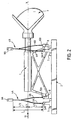
- Figure 2 is a side view of the device of Figure 1.
- Figure 3 illustrates the deformation of the blades of an element of suspension of the device of FIGS. 1 and 2, under the action of a force exerted parallel to the axis (X-X).
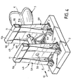
- Figure 4 is a perspective view of a second mode of the suspension and guiding device in translation according to the invention.
- Figure 5 is a side view of the device of Figure 4.
- Figures 6 and 7 illustrate the deformation of the device, in the case of the mode of FIGS. 4 and 5, for a displacement of the device, along the axis (X-X), in both meaning.
- Figure 8 shows the deformation of the blades of an element of suspension of the device of FIGS. 4 and 5, under the action of a force exerted parallel to the axis (X-X).
- the suspension and guiding device in translation for a device 1 intended to be moved, parallel to its longitudinal axis (X-X), relative to a fixed support 2, and able to carry, at 3, an optical instrument comprises a pair of suspension elements 4A, 4B.
- the suspension elements 4A, 4B are spaced along the axis longitudinal (X-X) and arranged at least substantially transversely said axis (X-X) while being flexible in parallel said axis (X-X).
- each suspension element 4A, 4B consists of a pair of blades 5A, 5B; 6A, 6B, one end of one of said blades (5A, respectively 6A) is integral with the support 2 and one end of the other of said blades (5B, respectively 6B) is integral of the device 1, the other ends of the blades 5A, 5B; 6A, 6B being integral with one another.
- the blades 5A, 6A are each in the form of two branches of which the lower end 5A.1, 6A.1 of each of them is fixed to the support 2 by being, for example, embedded in a respective support piece 7, linked to the support 2, while the lower end 5B.1, 6B.1 of blades 5B, 6B, in one piece, is recessed at the end a respective tab 8 secured to the device 1.
- the branches of the blades 5A, 6A are connected, to their upper ends 5A.2, 6A.2, by a blade transverse 9A, 9B joining the latter together, as well as at the upper end 5B.2, 6B.2 of the blades 5B, 6B.
- the point of application of the effort exerted by actuating means (only symbolized by arrow 10 on the drawing) on the elastic blades must be exerted on the axis (X-X), of so that if (L) is the distance between the ends upper and lower for embedding the blades 5A, 5B; 6A, 6B, the axis (X-X) is located in such a way that, at least substantially, the distance between the upper ends of the axis (X-X) is equal to the distance separating the lower embedding ends of the axis (X-X), i.e. to (L / 2); this in order to get a zero angular defect during the application of the force.
- each of suspension elements 4A, 4B consists of two pairs blades 5A, 5B; 6A, 6B previously described, arranged in symmetrical (or in opposition) to the plane median longitudinal of the assembly formed by the two said pairs of blades in rest condition of the actuating means 10, and in which the upper ends, integral with each other, with each pair of blades 5A, 5B; 5A, 5B, on the one hand, and 6A, 6B; 6A, 6B, on the other hand, are connected by a fastening element 11, working in tension / compression, consisting of two blades 11A, 11B whose width extends parallel to the axis (X-X), connecting the upper and lower ends, respectively, transverse blades 9A, 9B.
- each element of suspension 4A, 4B present, in condition of rest of the means actuation 10, a general form of inverted W, of which each "outside” branch is embedded in a room respective support 7 linked to support 2, while the “interior” branches are fixed, in common, at the end a tab 8 secured to the device 1.
- the blades have a length and mounting positions such as point of application of the force exerted by the actuating means 10 remains "central”.
- FIGS. 6 to 8 illustrate the deformations of the blades 5A, 5B; 6A, 6B for different strokes of the following device 1 the axis (X-X).
Landscapes
- Physics & Mathematics (AREA)
- General Physics & Mathematics (AREA)
- Optics & Photonics (AREA)
- Wind Motors (AREA)
- Springs (AREA)
- Vehicle Body Suspensions (AREA)
- Vibration Prevention Devices (AREA)
Claims (10)
- Aufhängungs- und translatorische Führungsvorrichtung für ein Gerät (1), das parallel zu einer Längsachse (X-X) verschoben werden soll, wobei die Vorrichtung Folgendes umfasst:dadurch gekennzeichnet, dass bei jedem Plattenpaar (5A, 5B; 6A, 6B) die anderen Enden der Platten des Paars durch ein entsprechendes Organ (9A oder 9B) fest miteinander verbunden werden.eine feste Halterung (2);mindestens ein Paar Aufhängungselemente (4A, 4B), die entlang der Längsachse (X-X) in einem bestimmten Abstand und mindestens fast quer zur genannten Achse (X-X) angeordnet sind, indem sie parallel zur Achse (X-X) flexibel sind, wobei jedes der Aufhängungselemente (4A, 4B) aus mindestens einem Paar Platten (5A, 5B; 6A, 6B) besteht und bei jedem Plattenpaar ein Ende einer der Platten fest mit der Halterung (2) und ein Ende der anderen der genannten Platten mit dem Gerät (1) verbunden ist; undsteuerbare Betätigungsmittel (10), die an den Aufhängungselementen parallel zur Längsachse (X-X) eine Kraft ausüben sollen,
- Vorrichtung nach Anspruch 1,
dadurch gekennzeichnet, dass bei jedem Plattenpaar eines jeden Aufhängungselements (4A, 48) eine der Platten (5A, 6A) in Form von zwei Schenkeln vorliegt, von denen jedes untere Ende (5A.1, 6A.1) an der Halterung (2) befestigt ist, wohingegen das untere Ende (5B.1, 6B.1) der anderen, aus einem Teil bestehenden Platte (5B, 6B) am Ende einer Pratze (8) befestigt ist, die fest mit dem Gerät (1) verbunden ist. - Vorrichtung nach Anspruch 2,
dadurch gekennzeichnet, dass das untere Ende (5A.1, 6A.1) jedes Schenkels jeweils in ein mit der genannten Halterung (2) verbundenes Auflageteil (7) eingebaut ist. - Vorrichtung nach Anspruch 2 oder Anspruch 3,
dadurch gekennzeichnet, dass die Schenkel der ersten Platten (5A, 6A) an ihren oberen Enden (5A.2, 6A.2) durch eine Querplatte (9A, 9B), die letztere fest miteinander verbindet, sowie am oberen Ende (5B.2, 6B.2) der genannten zweiten Platten verbunden sind. - Vorrichtung nach irgendeinem der Ansprüche 1 bis 4,
dadurch gekennzeichnet, dass jedes der Aufhängungselemente (4A, 4B) durch zwei Paare der Platten (5A, 5B; 6A, 6B) gebildet wird, die symmetrisch zur mittleren Längsebene der Einheit angeordnet sind, die durch die beiden genannten Plattenpaare in Ruhestellung des Betätigungsmittel (10) gebildet wird, und dadurch, dass die oberen, fest miteinander verbundenen Enden jedes Plattenpaars der Einheit durch ein Verbindungselement (11) verbunden sind, das mit Zug/Druck wirkt. - Vorrichtung nach Anspruch 4 und Anspruch 5,
dadurch gekennzeichnet, dass das Verbindungselement (11) aus zwei Platten (11A, 11B) besteht, deren Breite parallel zur Achse (X-X) verläuft, die das obere beziehungsweise das untere Ende der Querplatten (9A, 98) verbinden. - Vorrichtung nach Anspruch 5 oder Anspruch 6,
dadurch gekennzeichnet, dass jedes Aufhängungselement (4A,4B) in Ruhestellung der Betätigungsmittel (10) eine allgemeine Form eines umgedrehten W besitzt. - Vorrichtung nach Anspruch 7,
dadurch gekennzeichnet, dass jeder Außenschenkel des Aufhängungselements in Form eines umgedrehten W in ein entsprechendes, mit der Halterung (2) verbundenes Auflageteil (7) eingebaut ist, wohingegen die Innenschenkel beide am Ende einer Pratze (8) befestigt sind, die mit dem Gerät (1) ein Stück bildet. - Vorrichtung nach irgendeinem der Ansprüche 1 bis 8,
dadurch gekennzeichnet, dass der Angriffspunkt der von dem Betätigungsmittel (10) auf die elastischen Platten ausgeübten Kraft mindestens ungefähr auf der Achse (X-X) liegt, sodass die Achse (X-X), wenn (L) die Entfernung ist, die das obere Einbauende vom unteren Einbauende der Platten trennt, so liegt, dass die Entfernung, die die oberen Einbauenden von der Achse (X-X) trennt, ungefähr gleich der Entfernung ist, die die unteren Einbauenden von der Achse trennt, das heißt gleich (L/2). - Gerät, das parallel zu seiner Längsachse (X-X) in Bezug auf eine feste Halterung verschoben werden soll, dadurch gekennzeichnet, dass es mit einer Aufhängungs- und translatorischen Führungsvorrichtung nach irgendeinem der Ansprüche 1 bis 9 ausgerüstet ist.
Applications Claiming Priority (2)
| Application Number | Priority Date | Filing Date | Title |
|---|---|---|---|
| FR9608848A FR2751430B1 (fr) | 1996-07-16 | 1996-07-16 | Dispositif de suspension et de guidage en translation pour un appareil et appareil equipe d'un tel dispositif |
| FR9608848 | 1996-07-16 |
Publications (2)
| Publication Number | Publication Date |
|---|---|
| EP0819962A1 EP0819962A1 (de) | 1998-01-21 |
| EP0819962B1 true EP0819962B1 (de) | 2003-08-27 |
Family
ID=9494075
Family Applications (1)
| Application Number | Title | Priority Date | Filing Date |
|---|---|---|---|
| EP97401514A Expired - Lifetime EP0819962B1 (de) | 1996-07-16 | 1997-06-30 | Aufhängungs- und translatorische Führungsvorrichtung für ein Gerät und Gerät mit dieser Vorrichtung |
Country Status (6)
| Country | Link |
|---|---|
| US (1) | US5859731A (de) |
| EP (1) | EP0819962B1 (de) |
| CA (1) | CA2210514A1 (de) |
| DE (1) | DE69724359T2 (de) |
| ES (1) | ES2205150T3 (de) |
| FR (1) | FR2751430B1 (de) |
Families Citing this family (5)
| Publication number | Priority date | Publication date | Assignee | Title |
|---|---|---|---|---|
| DE10004661B4 (de) * | 2000-02-03 | 2008-10-16 | Leica Microsystems Cms Gmbh | Vorrichtung zum Schwenken eines Lichtstrahls |
| WO2008029281A2 (en) * | 2006-02-10 | 2008-03-13 | Invitrogen Corporation | Labeling and detection of post translationally modified proteins |
| US8295537B2 (en) * | 2010-03-31 | 2012-10-23 | Bose Corporation | Loudspeaker moment and torque balancing |
| US8295536B2 (en) * | 2010-03-31 | 2012-10-23 | Bose Corporation | Moving magnet levered loudspeaker |
| US9055370B2 (en) | 2012-08-31 | 2015-06-09 | Bose Corporation | Vibration-reducing passive radiators |
Family Cites Families (7)
| Publication number | Priority date | Publication date | Assignee | Title |
|---|---|---|---|---|
| US4209233A (en) * | 1978-11-06 | 1980-06-24 | Mta Kozponti Fizikai Kutato Intezete | Linear positioning device, preferably for optical measurements |
| US4961637A (en) * | 1988-10-14 | 1990-10-09 | Ou Jan Chou | Rear view lens apparatus for automotive vehicle |
| FR2648241B1 (fr) * | 1989-06-12 | 1991-09-27 | Aerospatiale | Dispositif de guidage et de manoeuvre d'un element mobile parallelement a un axe, et instrument optique le comportant |
| JP2982884B2 (ja) * | 1992-10-02 | 1999-11-29 | キヤノン株式会社 | 対物レンズ駆動装置 |
| US5450175A (en) * | 1993-07-27 | 1995-09-12 | Konica Corporation | Image forming apparatus having optical means for image magnification change |
| US5497272A (en) * | 1994-05-26 | 1996-03-05 | Umax Data Systems Inc. | Lens switching device for multi-lens optical scanners |
| GB2320636B (en) * | 1996-12-17 | 2000-09-27 | Umax Data Systems Inc | Opto-mechanical apparatus for moving and scanning in an optical system |
-
1996
- 1996-07-16 FR FR9608848A patent/FR2751430B1/fr not_active Expired - Lifetime
-
1997
- 1997-06-30 DE DE69724359T patent/DE69724359T2/de not_active Expired - Lifetime
- 1997-06-30 ES ES97401514T patent/ES2205150T3/es not_active Expired - Lifetime
- 1997-06-30 EP EP97401514A patent/EP0819962B1/de not_active Expired - Lifetime
- 1997-07-15 CA CA002210514A patent/CA2210514A1/fr not_active Abandoned
- 1997-07-16 US US08/895,022 patent/US5859731A/en not_active Expired - Lifetime
Also Published As
| Publication number | Publication date |
|---|---|
| EP0819962A1 (de) | 1998-01-21 |
| DE69724359D1 (de) | 2003-10-02 |
| US5859731A (en) | 1999-01-12 |
| CA2210514A1 (fr) | 1998-01-16 |
| FR2751430B1 (fr) | 1998-09-11 |
| FR2751430A1 (fr) | 1998-01-23 |
| DE69724359T2 (de) | 2004-06-24 |
| ES2205150T3 (es) | 2004-05-01 |
Similar Documents
| Publication | Publication Date | Title |
|---|---|---|
| EP0032101B1 (de) | Vorrichtung zum Anzeigen von Materialermüdung | |
| FR2685951A1 (fr) | Dispositif de controle de dimensions d'un objet, en particulier de diametres exterieurs ou interieurs de pieces mecaniques. | |
| FR2816578A1 (fr) | Pince pour fixer la tige de selle d'une bicyclette | |
| EP0560695A1 (de) | Vorrichtung enthaltend eine unabhängige Vorderbildung und Fersenhalter | |
| EP0624515A1 (de) | Stützstruktur für Flugzeugsitz und Sitz mit dieser Struktur | |
| WO2014184468A1 (fr) | Banc d'essai en fatigue oligocyclique ou en fatigue oligocyclique et polycyclique | |
| EP0468841B1 (de) | Bandförderer | |
| EP0819962A1 (de) | Aufhängungs- und translatorische Führungsvorrichtung für ein Gerät und Gerät mit dieser Vorrichtung | |
| EP0208616A2 (de) | Elastischer gedämpfter Anschlag | |
| WO1994028329A1 (fr) | Frein a disque a etrier coulissant | |
| FR2738497A1 (fr) | Patin a roues en ligne | |
| EP0442234B1 (de) | Scheibenwischerblatt, das eine grosse Biegsamkeit aufweist, insbesondere für stark gewölbte Scheiben eines Kraftfahrzeuges | |
| FR2583296A1 (fr) | Ski, notamment a usage de ski alpin | |
| FR2491425A1 (fr) | Dispositif de montage de selle, notamment pour bicyclette | |
| EP0587517A1 (de) | Einbau einer beweglichen Herzstückspitze in einer Kreuzung langer geschweisster Eisenbahnschienen und Verfahren dazu | |
| FR2631405A1 (fr) | Frein a disque et systeme de support pour un tel frein | |
| EP0403354B1 (de) | Führungsvorrichtung für ein mobiles Element parallel zu einer Achse und Instrument mit einer derartigen Führung | |
| FR2584354A1 (fr) | Dispositif d'essuyage pour nettoyer la surface d'une optique d'un feu de vehicule a moteur | |
| FR2555907A2 (fr) | Fixation de securite pour ski | |
| FR2732083A1 (fr) | Dispositif de connexion a montage simplifie pour assembler deux profiles | |
| FR2605845A1 (fr) | Plaque porte-moulinet pour cannes a peche | |
| FR2794826A1 (fr) | Support antivibratoire equipe d'un cable limiteur inextensible | |
| FR2965027A1 (fr) | Frein a disque a etrier flottant pour vehicule automobile | |
| EP0489629B1 (de) | Scheibenwischerarm mit Federstange, insbesondere für Kraftfahrzeuge | |
| FR2550752A1 (fr) | Pedalier a developpement variable |
Legal Events
| Date | Code | Title | Description |
|---|---|---|---|
| PUAI | Public reference made under article 153(3) epc to a published international application that has entered the european phase |
Free format text: ORIGINAL CODE: 0009012 |
|
| AK | Designated contracting states |
Kind code of ref document: A1 Designated state(s): DE ES GB IT |
|
| 17P | Request for examination filed |
Effective date: 19980206 |
|
| AKX | Designation fees paid |
Free format text: DE ES GB IT |
|
| RBV | Designated contracting states (corrected) |
Designated state(s): DE ES GB IT |
|
| RAP1 | Party data changed (applicant data changed or rights of an application transferred) |
Owner name: AEROSPATIALE MATRA |
|
| RAP1 | Party data changed (applicant data changed or rights of an application transferred) |
Owner name: ALCATEL SPACE INDUSTRIES |
|
| RAP1 | Party data changed (applicant data changed or rights of an application transferred) |
Owner name: ALCATEL |
|
| 17Q | First examination report despatched |
Effective date: 20021223 |
|
| GRAH | Despatch of communication of intention to grant a patent |
Free format text: ORIGINAL CODE: EPIDOS IGRA |
|
| GRAS | Grant fee paid |
Free format text: ORIGINAL CODE: EPIDOSNIGR3 |
|
| GRAA | (expected) grant |
Free format text: ORIGINAL CODE: 0009210 |
|
| AK | Designated contracting states |
Designated state(s): DE ES GB IT |
|
| REG | Reference to a national code |
Ref country code: GB Ref legal event code: FG4D Free format text: NOT ENGLISH |
|
| GBT | Gb: translation of ep patent filed (gb section 77(6)(a)/1977) | ||
| REF | Corresponds to: |
Ref document number: 69724359 Country of ref document: DE Date of ref document: 20031002 Kind code of ref document: P |
|
| REG | Reference to a national code |
Ref country code: ES Ref legal event code: FG2A Ref document number: 2205150 Country of ref document: ES Kind code of ref document: T3 |
|
| PLBE | No opposition filed within time limit |
Free format text: ORIGINAL CODE: 0009261 |
|
| STAA | Information on the status of an ep patent application or granted ep patent |
Free format text: STATUS: NO OPPOSITION FILED WITHIN TIME LIMIT |
|
| 26N | No opposition filed |
Effective date: 20040528 |
|
| PGFP | Annual fee paid to national office [announced via postgrant information from national office to epo] |
Ref country code: DE Payment date: 20160622 Year of fee payment: 20 Ref country code: ES Payment date: 20160527 Year of fee payment: 20 Ref country code: GB Payment date: 20160601 Year of fee payment: 20 |
|
| PGFP | Annual fee paid to national office [announced via postgrant information from national office to epo] |
Ref country code: IT Payment date: 20160621 Year of fee payment: 20 |
|
| REG | Reference to a national code |
Ref country code: DE Ref legal event code: R071 Ref document number: 69724359 Country of ref document: DE |
|
| REG | Reference to a national code |
Ref country code: GB Ref legal event code: PE20 Expiry date: 20170629 |
|
| PG25 | Lapsed in a contracting state [announced via postgrant information from national office to epo] |
Ref country code: GB Free format text: LAPSE BECAUSE OF EXPIRATION OF PROTECTION Effective date: 20170629 |
|
| REG | Reference to a national code |
Ref country code: ES Ref legal event code: FD2A Effective date: 20180508 |
|
| PG25 | Lapsed in a contracting state [announced via postgrant information from national office to epo] |
Ref country code: ES Free format text: LAPSE BECAUSE OF EXPIRATION OF PROTECTION Effective date: 20170701 |