EP0820085A1 - Procédé et dispositif de balayage pour une caméra à fente - Google Patents
Procédé et dispositif de balayage pour une caméra à fente Download PDFInfo
- Publication number
- EP0820085A1 EP0820085A1 EP97305381A EP97305381A EP0820085A1 EP 0820085 A1 EP0820085 A1 EP 0820085A1 EP 97305381 A EP97305381 A EP 97305381A EP 97305381 A EP97305381 A EP 97305381A EP 0820085 A1 EP0820085 A1 EP 0820085A1
- Authority
- EP
- European Patent Office
- Prior art keywords
- signal
- sweeping
- frequency
- trigger signal
- blanking
- Prior art date
- Legal status (The legal status is an assumption and is not a legal conclusion. Google has not performed a legal analysis and makes no representation as to the accuracy of the status listed.)
- Granted
Links
- 238000010408 sweeping Methods 0.000 title claims abstract description 164
- 238000000034 method Methods 0.000 title claims abstract description 27
- 238000010894 electron beam technology Methods 0.000 claims abstract description 69
- 230000005684 electric field Effects 0.000 claims description 16
- 230000001678 irradiating effect Effects 0.000 claims description 4
- OAICVXFJPJFONN-UHFFFAOYSA-N Phosphorus Chemical compound [P] OAICVXFJPJFONN-UHFFFAOYSA-N 0.000 abstract description 29
- 238000010586 diagram Methods 0.000 description 16
- 230000003287 optical effect Effects 0.000 description 14
- 230000001360 synchronised effect Effects 0.000 description 11
- RTAQQCXQSZGOHL-UHFFFAOYSA-N Titanium Chemical compound [Ti] RTAQQCXQSZGOHL-UHFFFAOYSA-N 0.000 description 2
- 229910052719 titanium Inorganic materials 0.000 description 2
- 239000010936 titanium Substances 0.000 description 2
- 230000001133 acceleration Effects 0.000 description 1
- 238000012986 modification Methods 0.000 description 1
- 230000004048 modification Effects 0.000 description 1
Images






Classifications
-
- G—PHYSICS
- G04—HOROLOGY
- G04F—TIME-INTERVAL MEASURING
- G04F13/00—Apparatus for measuring unknown time intervals by means not provided for in groups G04F5/00 - G04F10/00
- G04F13/02—Apparatus for measuring unknown time intervals by means not provided for in groups G04F5/00 - G04F10/00 using optical means
- G04F13/026—Measuring duration of ultra-short light pulses, e.g. in the pico-second range; particular detecting devices therefor
-
- H—ELECTRICITY
- H01—ELECTRIC ELEMENTS
- H01J—ELECTRIC DISCHARGE TUBES OR DISCHARGE LAMPS
- H01J31/00—Cathode ray tubes; Electron beam tubes
- H01J31/08—Cathode ray tubes; Electron beam tubes having a screen on or from which an image or pattern is formed, picked up, converted, or stored
- H01J31/50—Image-conversion or image-amplification tubes, i.e. having optical, X-ray, or analogous input, and optical output
- H01J31/501—Image-conversion or image-amplification tubes, i.e. having optical, X-ray, or analogous input, and optical output with an electrostatic electron optic system
- H01J31/502—Image-conversion or image-amplification tubes, i.e. having optical, X-ray, or analogous input, and optical output with an electrostatic electron optic system with means to interrupt the beam, e.g. shutter for high speed photography
Definitions
- the present invention relates to a sweeping technology for a streak tube that can detect optical events which occur in very short time intervals.
- streak tubes light to be measured is introduced onto a photocathode which generates a number of photoelectrons corresponding to the amount of light.
- the photoelectrons are accelerated and focused in an electron beam.
- a sweeping signal is applied to deflection plates provided in the path of the electron beam.
- the electron beam is deflected by the deflection plates, forming a streak image on a phosphor screen.
- the streak image is used to measure the strength of the introduced light.
- the streak tube When used in combination with a titanium sapphire laser light source for generating a light pulse at a high repeating frequency stabilized at about 100 MHz, the streak tube not only can measure extremely faint fluorescent light and the like, but can accurately accumulate faint streak images at the same position on the phosphor screen by applying to the deflection plate a sweeping signal in the form of a sinusoidal wave, synchronized with the high repeating frequency of the laser light source. Therefore, an optical event can be measured in a short time duration with few jitters and a high signal-to-noise ratio.
- Methods for applying a sweeping signal to the deflection plates are in a streak tube that are well-known in the art include a single sweeping method, synchronization scan sweeping method, duplex sweeping method, and elliptical sweeping method.
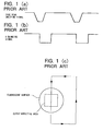
- the diagrams in Figures 1(a) through 1(c) illustrate the single sweeping method known in the art.
- Figure 1(a) shows a waveform of a synchronization scan sweeping signal
- Figure 1(b) shows the waveform of a horizontal (H) blanking signal
- Figure 1(c) shows the movement of the electron beam over the phosphor screen.
- the synchronization scan sweeping signal and horizontal blanking signal are generated in synchronicity with the light pulse output from the laser light source.
- the synchronization scan sweeping signal is applied to vertical deflection plates in the streak tube.
- the horizontal blanking signal is applied to the horizontal deflection plates in the streak tube.
- the electron beam issued when light to be measured is introduced onto the photocathode is deflected by the electric fields formed by the vertical and horizontal deflection plates.
- the electron beam is scanned over the phosphor screen as shown in Fig. 1(c).
- the horizontal blanking signal is at a low level and the synchronization scan sweeping signal is changing from the low level to the high level, the electron beam is swept to move across the output effective area on the phosphor screen.
- a streak image is therefore obtained for each period of the synchronization scan sweeping signal, in other words for each optical pulse output from the laser light source.
- the other conventional sweeping methods also form a streak image of the light to be measured on the phosphor screen for each pulse output from the laser light source.
- the fluorescent matter when exciting fluorescent matter by an optical pulse output from the laser light source and measuring the fluorescent light emitted from the fluorescent matter, if the life of the fluorescent light is longer than the period of the optical pulse output from the laser light source, the fluorescent matter will be excited by the next optical pulse, creating new fluorescent light, before generation of the first fluorescent light has sufficiently completed. In this example, the fluorescent light cannot be accurately measured.
- a sweeping method for a streak camera including a streak camera having an air-tight cylindrical container having a longitudinal axis, a photocathode that receives light to be measured and generates an electron beam into the air-tight cylindrical container, and an output member disposed in spaced apart relation with the photocathode and having an output effective area for receiving the electron beam; a first deflecting unit that generates an electrical field in a first direction substantially perpendicular to a direction in which the longitudinal axis extends; and a second deflection unit that generates an electric field in a second direction substantially perpendicular to both the first direction and the direction in which the longitudinal axis extends, comprises the steps of applying a sweeping signal to said first deflection unit to deflect the electron beam back and forth in the first direction, the sweeping signal having a predetermined frequency and a period determined by the predetermined frequency; and applying a blanking signal to said second deflection unit to deflect the electron beam back and forth
- a streak camera comprises a streak camera having an air-tight cylindrical container having a longitudinal axis, a photocathode that receives light to be measured and generates an electron beam into the air-tight cylindrical container, and an output member disposed in spaced apart relation with the photocathode and having an output effective area for receiving the electron beam;
- the blanking signal preferably has a first level and a second level lower than the first level.
- the electron beam scans across the output effective area of the output member.
- a duration of the second level of the blanking signal is advantageously substantially equal to a half of the period of the sweeping signal.
- the sweeping signal preferably changes substantially linearly from a first amplitude to a second amplitude.
- the period of time at which the light to be measured is incident upon the photocathode may be substantially equal to a half of the period of the sweeping signal.
- the duration of the second level of the blanking signal may be longer than the half of the period of the sweeping signal.
- the first trigger signal may be generated by photo-electrically converting light pulses having a predetermined repetition frequency, and the sweeping signal may be generated in synchronism with the first trigger signal.
- the light pulses are preferably generated from a light source. From the light pulses generated therefore, light pulses are extracted at a predetermined interval to generate a second trigger signal which is representative of timings at which extracted light pulses are output.
- the blanking signal is preferably generated in synchronism with the second trigger signal.
- the sweeping signal may be generated in synchronism with a first trigger signal which is output in synchronism with light pulses having a predetermined repetition frequency.
- the light pulses may be generated from a light source. From the light pulses generated therefrom, the light pulses may be extracted at a predetermined interval to generate a second trigger signal representative of timings at which extracted light pulses are output.
- the blanking signal is preferably generated in synchronism with the second trigger signal.
- a first trigger signal having a first frequency may be subjected to a frequency multiplication to generate a second trigger signal having a second frequency equal to the predetermined frequency of the sweeping signal.
- the first trigger signal is output in synchronism with light pulses having a frequency equal to the first frequency.
- the light pulses may be generated from a light source.
- the sweeping signal is generated in synchronism with the second trigger signal.
- the blanking signal may be generated in synchronism with the first trigger signal.
- a first trigger signal having a first frequency may be generated based on a second trigger signal having a second frequency lower than the first frequency.
- the second trigger signal is output in synchronism with light pulse having a predetermined repetition frequency.
- the light pulses are generated from a light source.
- the sweeping signal is generated in synchronism with the first trigger signal.
- the blanking signal may be generated in synchronism with the first trigger signal.
- the present invention also provides a streak camera system which implements the sweeping method described above.
- the present invention will be described with reference to the accompanying drawings in which:
- the streak tube 10 is an air-tight cylindrical container within which a vacuum is maintained.
- the streak tube 10 includes a photocathode 11, an accelerator electrode 12, a microchannel plate 13, a phosphor screen 14, vertical deflection plates 15, and horizontal deflection plates 16.
- the photocathode 11 is provided at one end of the streak tube 10.
- the photocathode 11 When light to be measured is incident upon the photocathode 11, the photocathode 11 generates a number of photoelectrons corresponding to the strength of the light.
- the photoelectrons are accelerated according to the acceleration voltage applied to the accelerator electrode 12.
- An electron beam of the photoelectrons passes through the air-tight container and reaches the microchannel plate 13 on the opposing end of the streak tube 10.
- the electron beam is amplified by the microchannel plate 13 and introduced onto the phosphor screen (output surface) 14, generating fluorescent light on that surface.
- the strength of the generated fluorescent light corresponds to the number of photoelectrons and energy in each of the photoelectrons, that is, in the strength of the light incident upon the photocathode.
- the vertical deflection plates 15 and horizontal deflection plates 16 are arranged as first and second pairs of deflection plates, respectively, between the accelerator electrode 12 and microchannel plate 13. Each pair of deflection plates are parallel electrode plates placed one plate on each side of the electron beam path. Electric fields are generated in both the vertical and horizontal directions by sweeping signals applied between the pairs of parallel electrode plates, which fields deflect the electron beam. Hence, by applying the sweeping signal to each of the vertical deflection plates 15 and horizontal deflection plates 16, time base variations in the strength of the introduced light can be measured as spatial variations on the phosphor screen 14.
- Figure 3 shows the structure of a streak camera system that includes a streak tube sweeping device of the present embodiment.
- This streak camera system includes a streak camera 100, a laser light source 20, and a streak tube sweeping device.
- a streak camera is defined to include not only the streak tube 10 but also a synchronization scan sweeping unit 17 and a horizontal (H) blanking signal generator 18 for outputting sweeping signals to be applied to the vertical deflection plates 15 and horizontal deflection plates 16, respectively.
- the synchronization scan sweeping unit 17 and horizontal blanking signal generator 18 will be considered as part of the sweeping device.
- Also provided as sweeping device are a pulse selector 31, a light trigger unit 32, and a timing generator 33. This diagram shows how a streak camera system is used to measure fluorescent light generated from a sample 40.
- the laser light source 20 outputs a stabilized light pulse at a high repetition frequency.
- a titanium sapphire laser light source having a repetition frequency of 80 MHz may be used.
- the laser light output from the laser light source 20 is divided into two by a half mirror 30, causing light to be input into both the pulse selector 31 and the light trigger unit 32.
- the light trigger unit 32 preferably a high-speed photoelectric converting element such as an avalanche photodiode, converts the light received into an electric pulse signal (synchronization scan trigger signal) proportionate to the amount of light received and outputs that signal to the synchronization scan sweeping unit 17. Based on this synchronization scan trigger signal, the synchronization scan sweeping unit 17 applies an appropriate synchronization scan sweeping signal to the vertical deflection plates 15 in the streak tube 10. The repetition frequency of this synchronization scan sweeping signal is equivalent to that of the light pulse output from the laser light source 20.
- the pulse selector 31 which may be provided with a polariscope, receives the other half of the light pulse split by the half mirror 30 and, based on the received light pulse outputs a light pulse at a low repetition frequency according to internal or externally input control signals.
- the light pulses output from the pulse selector 31 can be either light pulses thinned out with a uniform ratio for the input light pulses or single-shot light pulses.
- the pulse selector 31 outputs an electric trigger signal synchronized with the light pulse output.
- the light pulse output from the pulse selector 31 is introduced onto the sample 40, exciting fluorescent matter contained in the sample 40.
- the fluorescent light to be measured that is generated by the excited fluorescent matter is focused by an optical system 41 and introduced onto the photocathode 11 of the streak tube 10.
- the electric trigger signal is output from the pulse selector 31 to the timing generator 33, which outputs an electric pulse signal of a predetermined duration of time, synchronous to the timing at which light to be measured is introduced onto the photocathode 11.
- the horizontal blanking signal generator 18 outputs a horizontal blanking signal based on this electric pulse signal output from the timing generator 33, which horizontal blanking signal is applied to the horizontal deflection plates 16 in the streak tube 10.
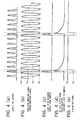
- FIGs. 4(a) through 4(e) show various signals generated and used in practicing the streak tube sweeping method of the present embodiment.
- Fig. 4(a) shows the changes in strength of the laser light output from the laser light source 20.
- Fig. 4(b) shows the synchronization scan sweeping signal output from the synchronization scan sweeping unit 17.
- This synchronization scan sweeping signal which is synchronous to the changes in strength of the laser light output from the laser light source 20, is applied to the vertical deflection plates 15 in the streak tube 10, creating an electric field in the vertical deflection plates 15.
- the generated electric field causes an electron beam moving from the photocathode 11 toward the phosphor screen 14 to be vertically deflected.
- the synchronization scan sweeping signal changes at a stabilized repetition frequency between the lowest level Vsi and the highest level V S4 .
- the synchronization scan sweeping signal is within a fixed range V S2 -V S3 (where V S1 ⁇ V S2 ⁇ V S3 ⁇ V S4 ), and the horizontal blanking signal is within a fixed range
- the electron beam generated by the photocathode 11 scans the output effective area of the phosphor screen 14.
- the synchronization scan sweeping signal can have either a saw-tooth waveform or a sinusoidal waveform, but it is desirable that the portion of signal between V S2 and V S3 be a straight line.
- V S4 - V S1 3 kV
- V S3 - V S2 200 V
- Fig. 4(c) shows the light pulse output from the pulse selector 31 and applied to the sample 40.
- This light pulse is the result of thinning down to a fixed ratio the laser light input from the laser light source 20.
- Fig. 4(d) shows the changes in strength of the fluorescent light to be measured, which light is generated by the sample 40 and introduced to the photocathode 11 when the light pulse of Fig. 4(c) is applied to the sample 40.
- This light to be measured is generated during each period that a light pulse is applied to the sample 40 and decays at a curve corresponding to the life of fluorescent light.
- the period of the light pulse output from the pulse selector 31 must be set to at least five times the life of fluorescent light to be sufficiently longer than the time required for the fluorescent light to decay.
- Fig. 4(e) shows the horizontal blanking signal output from the horizontal blanking signal generator 18.
- This signal which is synchronous with the light pulse output from the pulse selector 31, is applied to the horizontal deflection plates 16 in the streak tube 10, creating an electric field in the horizontal deflection plates 16.
- the generated electric field causes an electron beam moving from the photocathode 11 toward the phosphor screen 14 to be horizontally deflected.
- the horizontal blanking signal has a rectangular waveform with a lower level V H1 and an upper level V H2 . When the horizontal blanking signal is at the lower level V H1 and the synchronization scan sweeping signal is within a fixed range, the electron beam generated by the photocathode 11 scans the output effective area of the phosphor screen 14.
- the level of the synchronization scan sweeping signal must change only once from being greater than V S3 to being less than V S2 (or from being less than V S2 to being greater than V S3 ) during the time period that the horizontal blanking signal is at the lower level V H1 and while the light to be measured is being introduced onto the photocathode 11.
- the horizontal blanking signal generator 18 outputs a horizontal blanking signal capable of satisfying the above-described conditions.
- the synchronization scan sweeping signal reaches the maximum level V S4 just before the light to be measured is applied to the photocathode 11 and reaches the minimum level V S1 just after the light to be measured is applied to the photocathode 11.
- the synchronization scan sweeping signal changes from V S4 to V S1 during this time period.
- the horizontal blanking signal is at the lower level V H1 .
- Fig. 5(c) shows the waveform of the synchronization scan sweeping signal identical to that shown in Fig. 4(b).
- Fig. 5(b) shows the waveform of the horizontal blanking signal identical to that shown in Fig. 4(e).
- an output effective area 14a on the phosphor screen 14 is the area in which a streak image can effectively be output.
- the synchronization scan sweeping signal and the horizontal blanking signal change levels in the form A ⁇ B ⁇ C ⁇ D ⁇ E ⁇ F ⁇ E ⁇ ... ⁇ F ⁇ E ⁇ F ⁇ A.
- the electron beam created when the light to be measured is introduced onto the photocathode 11 sweeps a streak one time on the output effective area 11a.
- the streak image obtained on the output effective area 11a is linear in time if the synchronization scan sweeping signal passing from the level V S3 to the level V S2 is also linear in relation to time.
- the previous fluorescent light to be measured has sufficiently decayed. Accordingly, only information for a single streak image is obtained on the output effective area 14a of the phosphor screen 14, and the image is not overlapped with information for a previous streak image. Further, the obtained streak image is the one in the initial period of the fluorescent light information, and the strength of that fluorescent light changes greatly as time elapses. Therefore, the life of the fluorescent light issued from the sample 40 can be measured satisfactorily.
- the horizontal blanking signal is not restricted to the one shown in Figs. 4(e) and 5(b), but can also be a signal as shown in Figs. 6(e) and 7(b).
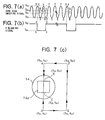
- Figs. 6(a) through 6(e) show various signals for practicing the streak tube sweeping method of a second embodiment to be described later.
- the strength variations of the laser light shown in Fig. 6(a), the synchronization scan sweeping signal in Fig. 6(b), the light pulse output from the pulse selector shown in Fig. 6(c), and the strength variations of the light to be measured shown in Fig. 6(d) are exactly the same as the respective diagrams Figs. 4(a) through 4(d) described above in the first embodiment.
- the horizontal blanking signal shown in Fig. 6(e) which is output from the horizontal blanking signal generator 18, differs from the horizontal blanking signal of Fig. 4(e) described above.
- the generated electric field causes an electron beam moving from the photocathode 11 toward the phosphor screen 14 to be horizontally deflected.
- the horizontal blanking signal has a rectangular waveform with a lower level V H1 and an upper level V H2 . When the horizontal blanking signal is at the lower level V H1 and the synchronization scan sweeping signal is within a fixed range, the electron beam generated by the photocathode 11 scans on the output effective area of the phosphor screen 14.
- the level of the synchronization scan sweeping signal changes only once from a level greater than V S3 to a level less than V S2 while the horizontal blanking signal is at the lower level V H1 and while the light to be measured is introduced onto the photocathode 11. Also during this time period, only one streak image is obtained.
- Fig. 7(a) shows the waveform of the synchronization scan sweeping signal identical to that shown in Fig. 6(b).
- Fig. 7(b) shows the waveform of the horizontal blanking signal identical to that shown in Fig. 6(e).
- Fig. 7(c) shows the movement of the electron beam across the output effective area 14a on the phosphor screen 14.
- the scanning position of the electron beam returns from point D via points C and B to point A, and again moves from point A to point B to point C and to point D.
- the scanning position of the electron beam moves forward from A to D, back to A, and forward again to D.
- the light to be measured is not introduced onto the photocathode 11 of the streak tube 10, and therefore a streak image is not obtained on the output effective area 14a. Only when the migrating position of the electron beam moves a second time from point B to point C is the light introduced onto the photocathode 11, allowing a streak image to be obtained on the output effective area 14a.
- the electron beam sweeps a streak one time across the output effective area 11a.
- the streak image obtained on the output effective area 11a is linear in time if the synchronization scan sweeping signal passing from the level V S3 to the level V S2 is also linear in relation to time.
- the sweeping device for generating a synchronization scan sweeping signal and a horizontal blanking signal described above is not limited to the configuration shown in Fig. 3. Other possible configurations for streak tube sweeping device will be described below.
- Fig. 8 shows the structure of a streak camera system that includes the streak tube sweeping device of the second embodiment.
- this streak camera system differs at two points.
- the laser light source 20 outputs an electric trigger signal (synchronization scan trigger signal) representing the output timing of light pulses.
- the synchronization scan sweeping unit 17 generates a synchronization scan sweeping signal based on the synchronization scan trigger signal output from the laser light source 20.
- the latter Based on an electric trigger signal output from an internal oscillating circuit contained in the laser light source 20, the latter outputs both a stabilized light pulse at a high repetition frequency as shown in Fig. 4(a) and the electric trigger signal as a synchronization scan trigger signal which signal is applied to the synchronization scan sweeping unit 17.
- the latter unit 17 generates a synchronization scan sweeping signal based on the synchronization scan trigger signal.
- the synchronization scan sweeping signal is applied to the vertical deflection plates 15 of the streak tube 10.
- the pulse selector 31 receives the high repetition frequency light pulse output from the laser light source 20 and, based on those light pulses, outputs a light pulse at a low repetition frequency as shown in Fig. 4(c) according to internal or externally input control signal. In addition, the pulse selector 31 outputs an electric trigger signal synchronized with the light pulse output.
- the light pulse output from the pulse selector 31 is introduced onto the sample 40, exciting fluorescent matter contained in the sample 40.
- the fluorescent light to be measured (as shown in Fig. 4(d)) that is generated by the excited fluorescent matter is focused by the optical system 41 and introduced onto the photocathode 11 of the streak tube 10.
- the electric trigger signal is output from the pulse selector 31 to the timing generator 33, which outputs an electric pulse signal of a predetermined duration of time, synchronous to the timing at which light to be measured is introduced onto the photocathode 11.
- the horizontal blanking signal generator 18 outputs a horizontal blanking signal based on this electric pulse signal output from the timing generator 33, which horizontal blanking signal is applied to the horizontal deflection plates 16 in the streak tube 10.
- the synchronization scan sweeping signal and horizontal blanking signal are exactly the same as described in the first embodiment.
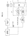
- Fig. 9 shows the structure of a streak camera system that includes the streak tube sweeping device of the third embodiment.
- a laser light source 21 outputs a stabilized light pulse at a low repetition frequency based on an electric trigger signal output from an internal oscillating circuit contained in the laser light source 21.
- the laser light source 21 outputs the electrical trigger signal as well.
- the light pulse output from the laser light source 21 is introduced onto the sample 40, exciting fluorescent matter contained in the sample 40.
- the fluorescent light to be measured that is generated by the excited fluorescent matter is focused by the optical system 41 and introduced onto the photocathode 11 of the streak tube 10.
- a frequency multiplier 34 receives the electric trigger signal output from the laser light source 21, multiplies the frequency of the signal, and outputs a synchronization scan trigger signal with the multiplied frequency.
- the synchronization scan sweeping unit 17 generates a synchronization scan sweeping signal based on the synchronization scan trigger signal.
- the synchronization scan sweeping signal is applied to the vertical deflection plates 15 of the streak tube 10.
- the electric trigger signal is output from the laser light source 21 to the timing generator 33, which outputs an electric pulse signal of a predetermined duration of time, synchronous to the timing at which light to be measured is introduced onto the photocathode 11.
- the horizontal blanking signal generator 18 outputs a horizontal blanking signal based on this electric pulse signal output from the timing generator 33, which horizontal blanking signal is applied to the horizontal deflection plates 16 in the streak tube 10.
- the synchronization scan sweeping signal and horizontal blanking signal are exactly the same as described in the first embodiment.
- Fig. 10 shows the structure of a streak camera system that includes the streak tube sweeping device of the fourth embodiment.
- this streak camera system differs in that a frequency synthesizer 35 is provided in place of the frequency multiplier 34.
- the laser light source 21 Based on electric trigger signals output from an internal oscillating circuit contained in the laser light source 21, the laser light source 21 outputs a stabilized light pulse at a low repetition frequency, as well as an electric trigger signal and a synchronization signal synchronous with the electric trigger signal.
- the light pulse output from the laser light source 21 is introduced onto the sample 40, exciting fluorescent matter contained in the sample 40.
- the fluorescent light to be measured that is generated by the excited fluorescent matter is focused by the optical system 41 and introduced onto the photocathode 11 of the streak tube 10.
- the frequency synthesizer 35 receives the synchronization signal output from the laser light source 21, and outputs a synchronization scan trigger signal at a high frequency in synchronism with the synchronization signal.
- the synchronization scan sweeping unit 17 generates a synchronization scan sweeping signal based on the synchronization scan trigger signal.
- the synchronization scan sweeping signal is applied to the vertical deflection plates 15 of the streak tube 10.
- the electric trigger signal is output from the laser light source 21 and applied to the timing generator 33, which outputs an electric pulse signal of a predetermined duration of time, synchronous to the timing at which light to be measured is introduced onto the photocathode 11.
- the horizontal blanking signal generator 18 outputs a horizontal blanking signal based on this electric pulse signal output from the timing generator 33, which horizontal blanking signal is applied to the horizontal deflection plates 16 in the streak tube 10.
- the synchronization scan sweeping signal and horizontal blanking signal are exactly the same as described in the first embodiment.
- the pulse selector 31 and laser light source 21 could be capable of variably setting the repetition frequency of the light pulse to suit the life of the fluorescent light output from the sample 40.
- the period in which the horizontal blanking signal is at the lower level V H1 need not be limited to a time period including the beginning period in which the light to be measured is applied to the photocathode 11, but can be set to elapse for a fixed time. However, it is important in this case that only one streak image can be formed on the phosphor screen 14 for each pulse of the horizontal blanking signal.
- the sweeping signal applied to the vertical deflection plates 15 has a sinusoidal waveform.
- the sweeping signal of the present invention is not limited to a sinusoidal waveform, but may have another waveform, such as a trapezoidal waveform or a saw-tooth waveform.
Landscapes
- Physics & Mathematics (AREA)
- Nonlinear Science (AREA)
- Optics & Photonics (AREA)
- General Physics & Mathematics (AREA)
- Image-Pickup Tubes, Image-Amplification Tubes, And Storage Tubes (AREA)
- Photometry And Measurement Of Optical Pulse Characteristics (AREA)
Applications Claiming Priority (3)
| Application Number | Priority Date | Filing Date | Title |
|---|---|---|---|
| JP08190897A JP3079042B2 (ja) | 1996-07-19 | 1996-07-19 | ストリーク管の掃引方法および掃引装置 |
| JP19089796 | 1996-07-19 | ||
| JP190897/96 | 1996-07-19 |
Publications (2)
| Publication Number | Publication Date |
|---|---|
| EP0820085A1 true EP0820085A1 (fr) | 1998-01-21 |
| EP0820085B1 EP0820085B1 (fr) | 2002-02-27 |
Family
ID=16265549
Family Applications (1)
| Application Number | Title | Priority Date | Filing Date |
|---|---|---|---|
| EP97305381A Expired - Lifetime EP0820085B1 (fr) | 1996-07-19 | 1997-07-18 | Procédé et dispositif de balayage pour une caméra à fente |
Country Status (4)
| Country | Link |
|---|---|
| US (1) | US5990944A (fr) |
| EP (1) | EP0820085B1 (fr) |
| JP (1) | JP3079042B2 (fr) |
| DE (1) | DE69710649T2 (fr) |
Cited By (3)
| Publication number | Priority date | Publication date | Assignee | Title |
|---|---|---|---|---|
| CN106154286B (zh) * | 2016-07-27 | 2018-06-08 | 北京理工大学 | 一种新型的非扫描多光谱条纹管激光成像系统 |
| CN110095186A (zh) * | 2018-01-30 | 2019-08-06 | 应用材料以色列公司 | 光检测器和用于检测光的方法 |
| US11268849B2 (en) | 2019-04-22 | 2022-03-08 | Applied Materials Israel Ltd. | Sensing unit having photon to electron converter and a method |
Families Citing this family (9)
| Publication number | Priority date | Publication date | Assignee | Title |
|---|---|---|---|---|
| JP4348576B2 (ja) * | 1999-07-08 | 2009-10-21 | ソニー株式会社 | 画像処理装置および方法、並びに記録媒体 |
| JP4567229B2 (ja) * | 2001-04-11 | 2010-10-20 | 浜松ホトニクス株式会社 | 光波形測定装置 |
| JP4598407B2 (ja) * | 2004-01-09 | 2010-12-15 | 浜松ホトニクス株式会社 | レーザ加工方法及びレーザ加工装置 |
| JP4601965B2 (ja) * | 2004-01-09 | 2010-12-22 | 浜松ホトニクス株式会社 | レーザ加工方法及びレーザ加工装置 |
| JP4509578B2 (ja) | 2004-01-09 | 2010-07-21 | 浜松ホトニクス株式会社 | レーザ加工方法及びレーザ加工装置 |
| DE102006022878B3 (de) * | 2006-05-15 | 2007-09-06 | Sartorius Biotech Gmbh | Verfahren und Detektionsvorrichtung zur bildgebenden Erfassung einer Probe |
| CN103048652B (zh) * | 2013-01-23 | 2014-08-20 | 哈尔滨工业大学 | 带多个偏转电场的无狭缝成像条纹管及其成像处理方法 |
| FR3034578B1 (fr) * | 2015-03-30 | 2018-04-27 | Horiba Abx Sas | Procede et dispositif de declenchement de sources lumineuses impulsionnelles |
| WO2025089055A1 (fr) * | 2023-10-26 | 2025-05-01 | 浜松ホトニクス株式会社 | Dispositif de mesure de signal électrique et procédé de mesure de signal électrique |
Citations (4)
| Publication number | Priority date | Publication date | Assignee | Title |
|---|---|---|---|---|
| US4413178A (en) * | 1981-03-23 | 1983-11-01 | University Of Rochester | Sweep drive circuit for a streak camera |
| GB2186075A (en) * | 1985-12-16 | 1987-08-05 | Hamamatsu Photonics Kk | Light pulse measuring instrument |
| US4740685A (en) * | 1986-02-14 | 1988-04-26 | Hamamatsu Photonics Kabushiki Kaisha | Double sweep streak camera device |
| US4945224A (en) * | 1987-06-30 | 1990-07-31 | Hamamatsu Photonics Kabushiki Kaisha | Optical waveform observing apparatus |
Family Cites Families (8)
| Publication number | Priority date | Publication date | Assignee | Title |
|---|---|---|---|---|
| DE3542973A1 (de) * | 1985-12-05 | 1987-06-11 | Bosch Gmbh Robert | Abgleichsverfahren zur automatischen strahlausrichtung in fernsehaufnahmeroehren |
| JPS62142235A (ja) * | 1985-12-16 | 1987-06-25 | Hamamatsu Photonics Kk | ストリ−クカメラ装置 |
| GB2226693B (en) * | 1988-12-28 | 1993-09-01 | Hamamatsu Photonics Kk | Optical waveform observing apparatus |
| GB2226631B (en) * | 1988-12-28 | 1992-10-21 | Hamamatsu Photonics Kk | Optical waveform observing apparatus |
| JP2709135B2 (ja) * | 1989-04-11 | 1998-02-04 | 浜松ホトニクス株式会社 | 光信号検出装置 |
| JPH0367447A (ja) * | 1989-08-04 | 1991-03-22 | Hamamatsu Photonics Kk | 電子管ゲート方法及び電子管 |
| JP3128803B2 (ja) * | 1990-04-27 | 2001-01-29 | 日本精工株式会社 | 転がり軸受 |
| JPH0689523B2 (ja) * | 1990-06-02 | 1994-11-09 | 前田道路株式会社 | 融雪レンガ舗装材と融雪レンガ舗装材の製造方法 |
-
1996
- 1996-07-19 JP JP08190897A patent/JP3079042B2/ja not_active Expired - Fee Related
-
1997
- 1997-07-18 US US08/896,951 patent/US5990944A/en not_active Expired - Lifetime
- 1997-07-18 DE DE69710649T patent/DE69710649T2/de not_active Expired - Lifetime
- 1997-07-18 EP EP97305381A patent/EP0820085B1/fr not_active Expired - Lifetime
Patent Citations (4)
| Publication number | Priority date | Publication date | Assignee | Title |
|---|---|---|---|---|
| US4413178A (en) * | 1981-03-23 | 1983-11-01 | University Of Rochester | Sweep drive circuit for a streak camera |
| GB2186075A (en) * | 1985-12-16 | 1987-08-05 | Hamamatsu Photonics Kk | Light pulse measuring instrument |
| US4740685A (en) * | 1986-02-14 | 1988-04-26 | Hamamatsu Photonics Kabushiki Kaisha | Double sweep streak camera device |
| US4945224A (en) * | 1987-06-30 | 1990-07-31 | Hamamatsu Photonics Kabushiki Kaisha | Optical waveform observing apparatus |
Non-Patent Citations (1)
| Title |
|---|
| SIU-PING HONG: "gaseous breakdown studies using a modified image converter streak camera", REVIEW OF SCIENTIFIC INSTRUMENTS, vol. 52, no. 12, December 1981 (1981-12-01), pages 1824 - 1829, XP002044386 * |
Cited By (5)
| Publication number | Priority date | Publication date | Assignee | Title |
|---|---|---|---|---|
| CN106154286B (zh) * | 2016-07-27 | 2018-06-08 | 北京理工大学 | 一种新型的非扫描多光谱条纹管激光成像系统 |
| CN110095186A (zh) * | 2018-01-30 | 2019-08-06 | 应用材料以色列公司 | 光检测器和用于检测光的方法 |
| CN110095186B (zh) * | 2018-01-30 | 2020-06-19 | 应用材料以色列公司 | 光检测器和用于检测光的方法 |
| US11268849B2 (en) | 2019-04-22 | 2022-03-08 | Applied Materials Israel Ltd. | Sensing unit having photon to electron converter and a method |
| US11774281B2 (en) | 2019-04-22 | 2023-10-03 | Applied Materials Israel Ltd. | Sensing unit having photon to electron converter |
Also Published As
| Publication number | Publication date |
|---|---|
| DE69710649T2 (de) | 2002-10-17 |
| DE69710649D1 (de) | 2002-04-04 |
| US5990944A (en) | 1999-11-23 |
| EP0820085B1 (fr) | 2002-02-27 |
| JP3079042B2 (ja) | 2000-08-21 |
| JPH1038681A (ja) | 1998-02-13 |
Similar Documents
| Publication | Publication Date | Title |
|---|---|---|
| EP0820085B1 (fr) | Procédé et dispositif de balayage pour une caméra à fente | |
| US4220853A (en) | Method for the contactless measurement of the potential waveform in an electronic component and arrangement for implementing the method | |
| GB2133875A (en) | Light pulse measuring apparatus | |
| US4461572A (en) | Instrument for measuring light emission induced by repetitive stimulation of the same type | |
| US4740685A (en) | Double sweep streak camera device | |
| US4704634A (en) | Streak tube having image slitting means for transmitting slit electron images of an object | |
| US4801796A (en) | Streak camera unit with elliptical deflection | |
| US5032714A (en) | Light waveform measuring device including a streak camera | |
| JP3571467B2 (ja) | 光波形測定装置 | |
| EP0843240B1 (fr) | Dispositif d'enregistrement du motif spatial d'un faisceau lumineux | |
| US4942293A (en) | Optical waveform observing apparatus | |
| EP0392794B1 (fr) | Détecteur d'un signal optique | |
| JP2680398B2 (ja) | 光波形測定装置 | |
| GB2227831A (en) | Optical waveform observing apparatus | |
| US4947031A (en) | Sampling streak tube with accelerating electrode plate having an opening | |
| JPH02234050A (ja) | 光波形測定装置 | |
| JPH056123B2 (fr) | ||
| JP2970961B2 (ja) | 光波形測定装置 | |
| JPH0140938B2 (fr) | ||
| CN119414442A (zh) | 同步辐射x射线脉冲时间宽度测量装置 | |
| SU1051613A1 (ru) | Способ записи информации на мишени электронно-лучевого прибора | |
| JPH0230653B2 (ja) | Kosokukurikaeshiparusuhikarikeisokuyodenshikansochi | |
| JPH056122B2 (fr) | ||
| SU1198766A1 (ru) | Устройство для определения вероятностных характеристик случайной величины | |
| JP2656106B2 (ja) | 光波形測定装置 |
Legal Events
| Date | Code | Title | Description |
|---|---|---|---|
| PUAI | Public reference made under article 153(3) epc to a published international application that has entered the european phase |
Free format text: ORIGINAL CODE: 0009012 |
|
| AK | Designated contracting states |
Kind code of ref document: A1 Designated state(s): DE FR GB |
|
| 17P | Request for examination filed |
Effective date: 19980703 |
|
| AKX | Designation fees paid |
Free format text: DE FR GB |
|
| RBV | Designated contracting states (corrected) |
Designated state(s): DE FR GB |
|
| GRAG | Despatch of communication of intention to grant |
Free format text: ORIGINAL CODE: EPIDOS AGRA |
|
| 17Q | First examination report despatched |
Effective date: 20010213 |
|
| GRAG | Despatch of communication of intention to grant |
Free format text: ORIGINAL CODE: EPIDOS AGRA |
|
| GRAG | Despatch of communication of intention to grant |
Free format text: ORIGINAL CODE: EPIDOS AGRA |
|
| GRAH | Despatch of communication of intention to grant a patent |
Free format text: ORIGINAL CODE: EPIDOS IGRA |
|
| GRAH | Despatch of communication of intention to grant a patent |
Free format text: ORIGINAL CODE: EPIDOS IGRA |
|
| REG | Reference to a national code |
Ref country code: GB Ref legal event code: IF02 |
|
| GRAA | (expected) grant |
Free format text: ORIGINAL CODE: 0009210 |
|
| AK | Designated contracting states |
Kind code of ref document: B1 Designated state(s): DE FR GB |
|
| REF | Corresponds to: |
Ref document number: 69710649 Country of ref document: DE Date of ref document: 20020404 |
|
| ET | Fr: translation filed | ||
| PLBE | No opposition filed within time limit |
Free format text: ORIGINAL CODE: 0009261 |
|
| STAA | Information on the status of an ep patent application or granted ep patent |
Free format text: STATUS: NO OPPOSITION FILED WITHIN TIME LIMIT |
|
| 26N | No opposition filed |
Effective date: 20021128 |
|
| REG | Reference to a national code |
Ref country code: FR Ref legal event code: PLFP Year of fee payment: 20 |
|
| PGFP | Annual fee paid to national office [announced via postgrant information from national office to epo] |
Ref country code: FR Payment date: 20160613 Year of fee payment: 20 |
|
| PGFP | Annual fee paid to national office [announced via postgrant information from national office to epo] |
Ref country code: GB Payment date: 20160713 Year of fee payment: 20 Ref country code: DE Payment date: 20160712 Year of fee payment: 20 |
|
| REG | Reference to a national code |
Ref country code: DE Ref legal event code: R071 Ref document number: 69710649 Country of ref document: DE |
|
| REG | Reference to a national code |
Ref country code: GB Ref legal event code: PE20 Expiry date: 20170717 |
|
| PG25 | Lapsed in a contracting state [announced via postgrant information from national office to epo] |
Ref country code: GB Free format text: LAPSE BECAUSE OF EXPIRATION OF PROTECTION Effective date: 20170717 |