EP0820833B1 - Vorrichtung zum Ausschneiden und Einschweissen von Blechronden in ein Blech - Google Patents
Vorrichtung zum Ausschneiden und Einschweissen von Blechronden in ein Blech Download PDFInfo
- Publication number
- EP0820833B1 EP0820833B1 EP97890136A EP97890136A EP0820833B1 EP 0820833 B1 EP0820833 B1 EP 0820833B1 EP 97890136 A EP97890136 A EP 97890136A EP 97890136 A EP97890136 A EP 97890136A EP 0820833 B1 EP0820833 B1 EP 0820833B1
- Authority
- EP
- European Patent Office
- Prior art keywords
- sheet
- welding
- metal
- cutting out
- discs according
- Prior art date
- Legal status (The legal status is an assumption and is not a legal conclusion. Google has not performed a legal analysis and makes no representation as to the accuracy of the status listed.)
- Expired - Lifetime
Links
- 238000003466 welding Methods 0.000 title claims abstract description 69
- 238000005520 cutting process Methods 0.000 title claims abstract description 59
- 229910052751 metal Inorganic materials 0.000 claims description 62
- 239000002184 metal Substances 0.000 claims description 62
- 238000003801 milling Methods 0.000 claims description 11
- RYGMFSIKBFXOCR-UHFFFAOYSA-N Copper Chemical compound [Cu] RYGMFSIKBFXOCR-UHFFFAOYSA-N 0.000 claims description 8
- 229910052802 copper Inorganic materials 0.000 claims description 6
- 239000010949 copper Substances 0.000 claims description 6
- 238000007789 sealing Methods 0.000 claims description 6
- 239000000463 material Substances 0.000 claims description 3
- 239000003302 ferromagnetic material Substances 0.000 claims description 2
- 229910000831 Steel Inorganic materials 0.000 abstract description 7
- 239000010959 steel Substances 0.000 abstract description 7
- 238000000034 method Methods 0.000 description 9
- XEEYBQQBJWHFJM-UHFFFAOYSA-N Iron Chemical compound [Fe] XEEYBQQBJWHFJM-UHFFFAOYSA-N 0.000 description 8
- 238000004519 manufacturing process Methods 0.000 description 7
- 230000005291 magnetic effect Effects 0.000 description 6
- PXHVJJICTQNCMI-UHFFFAOYSA-N Nickel Chemical compound [Ni] PXHVJJICTQNCMI-UHFFFAOYSA-N 0.000 description 4
- 229910052742 iron Inorganic materials 0.000 description 4
- 229910052782 aluminium Inorganic materials 0.000 description 3
- XAGFODPZIPBFFR-UHFFFAOYSA-N aluminium Chemical compound [Al] XAGFODPZIPBFFR-UHFFFAOYSA-N 0.000 description 3
- 239000011324 bead Substances 0.000 description 3
- 229910052799 carbon Inorganic materials 0.000 description 3
- OKTJSMMVPCPJKN-UHFFFAOYSA-N Carbon Chemical compound [C] OKTJSMMVPCPJKN-UHFFFAOYSA-N 0.000 description 2
- VYZAMTAEIAYCRO-UHFFFAOYSA-N Chromium Chemical compound [Cr] VYZAMTAEIAYCRO-UHFFFAOYSA-N 0.000 description 2
- 238000010276 construction Methods 0.000 description 2
- 230000005294 ferromagnetic effect Effects 0.000 description 2
- 238000010438 heat treatment Methods 0.000 description 2
- 239000012535 impurity Substances 0.000 description 2
- 238000003754 machining Methods 0.000 description 2
- 229910052759 nickel Inorganic materials 0.000 description 2
- 238000007665 sagging Methods 0.000 description 2
- 238000006467 substitution reaction Methods 0.000 description 2
- PWHULOQIROXLJO-UHFFFAOYSA-N Manganese Chemical compound [Mn] PWHULOQIROXLJO-UHFFFAOYSA-N 0.000 description 1
- ATJFFYVFTNAWJD-UHFFFAOYSA-N Tin Chemical compound [Sn] ATJFFYVFTNAWJD-UHFFFAOYSA-N 0.000 description 1
- RTAQQCXQSZGOHL-UHFFFAOYSA-N Titanium Chemical compound [Ti] RTAQQCXQSZGOHL-UHFFFAOYSA-N 0.000 description 1
- 230000005856 abnormality Effects 0.000 description 1
- 238000000137 annealing Methods 0.000 description 1
- 239000011093 chipboard Substances 0.000 description 1
- 238000005253 cladding Methods 0.000 description 1
- 238000010273 cold forging Methods 0.000 description 1
- 238000002485 combustion reaction Methods 0.000 description 1
- 230000001143 conditioned effect Effects 0.000 description 1
- 238000011109 contamination Methods 0.000 description 1
- 238000001816 cooling Methods 0.000 description 1
- 230000002950 deficient Effects 0.000 description 1
- 230000006735 deficit Effects 0.000 description 1
- 230000005292 diamagnetic effect Effects 0.000 description 1
- 239000000945 filler Substances 0.000 description 1
- 239000011521 glass Substances 0.000 description 1
- 229910052748 manganese Inorganic materials 0.000 description 1
- 239000011572 manganese Substances 0.000 description 1
- 239000000203 mixture Substances 0.000 description 1
- 229910052758 niobium Inorganic materials 0.000 description 1
- 239000010955 niobium Substances 0.000 description 1
- GUCVJGMIXFAOAE-UHFFFAOYSA-N niobium atom Chemical compound [Nb] GUCVJGMIXFAOAE-UHFFFAOYSA-N 0.000 description 1
- 230000005298 paramagnetic effect Effects 0.000 description 1
- 239000004033 plastic Substances 0.000 description 1
- 239000002985 plastic film Substances 0.000 description 1
- 229920006255 plastic film Polymers 0.000 description 1
- 238000007517 polishing process Methods 0.000 description 1
- 230000008439 repair process Effects 0.000 description 1
- 229910052710 silicon Inorganic materials 0.000 description 1
- 239000010703 silicon Substances 0.000 description 1
- 238000005496 tempering Methods 0.000 description 1
- 230000008646 thermal stress Effects 0.000 description 1
- 239000010936 titanium Substances 0.000 description 1
- 229910052719 titanium Inorganic materials 0.000 description 1
- 238000013022 venting Methods 0.000 description 1
- 239000002699 waste material Substances 0.000 description 1
- XLYOFNOQVPJJNP-UHFFFAOYSA-N water Substances O XLYOFNOQVPJJNP-UHFFFAOYSA-N 0.000 description 1
Images



Classifications
-
- B—PERFORMING OPERATIONS; TRANSPORTING
- B23—MACHINE TOOLS; METAL-WORKING NOT OTHERWISE PROVIDED FOR
- B23K—SOLDERING OR UNSOLDERING; WELDING; CLADDING OR PLATING BY SOLDERING OR WELDING; CUTTING BY APPLYING HEAT LOCALLY, e.g. FLAME CUTTING; WORKING BY LASER BEAM
- B23K9/00—Arc welding or cutting
- B23K9/12—Automatic feeding or moving of electrodes or work for spot or seam welding or cutting
-
- B—PERFORMING OPERATIONS; TRANSPORTING
- B23—MACHINE TOOLS; METAL-WORKING NOT OTHERWISE PROVIDED FOR
- B23K—SOLDERING OR UNSOLDERING; WELDING; CLADDING OR PLATING BY SOLDERING OR WELDING; CUTTING BY APPLYING HEAT LOCALLY, e.g. FLAME CUTTING; WORKING BY LASER BEAM
- B23K37/00—Auxiliary devices or processes, not specially adapted for a procedure covered by only one of the other main groups of this subclass
- B23K37/02—Carriages for supporting the welding or cutting element
- B23K37/0264—Carriages for supporting the welding or cutting element magnetically attached to the workpiece
-
- B—PERFORMING OPERATIONS; TRANSPORTING
- B23—MACHINE TOOLS; METAL-WORKING NOT OTHERWISE PROVIDED FOR
- B23K—SOLDERING OR UNSOLDERING; WELDING; CLADDING OR PLATING BY SOLDERING OR WELDING; CUTTING BY APPLYING HEAT LOCALLY, e.g. FLAME CUTTING; WORKING BY LASER BEAM
- B23K37/00—Auxiliary devices or processes, not specially adapted for a procedure covered by only one of the other main groups of this subclass
- B23K37/02—Carriages for supporting the welding or cutting element
- B23K37/0211—Carriages for supporting the welding or cutting element travelling on a guide member, e.g. rail, track
-
- B—PERFORMING OPERATIONS; TRANSPORTING
- B23—MACHINE TOOLS; METAL-WORKING NOT OTHERWISE PROVIDED FOR
- B23K—SOLDERING OR UNSOLDERING; WELDING; CLADDING OR PLATING BY SOLDERING OR WELDING; CUTTING BY APPLYING HEAT LOCALLY, e.g. FLAME CUTTING; WORKING BY LASER BEAM
- B23K37/00—Auxiliary devices or processes, not specially adapted for a procedure covered by only one of the other main groups of this subclass
- B23K37/02—Carriages for supporting the welding or cutting element
- B23K37/0282—Carriages forming part of a welding unit
-
- B—PERFORMING OPERATIONS; TRANSPORTING
- B23—MACHINE TOOLS; METAL-WORKING NOT OTHERWISE PROVIDED FOR
- B23K—SOLDERING OR UNSOLDERING; WELDING; CLADDING OR PLATING BY SOLDERING OR WELDING; CUTTING BY APPLYING HEAT LOCALLY, e.g. FLAME CUTTING; WORKING BY LASER BEAM
- B23K9/00—Arc welding or cutting
- B23K9/18—Submerged-arc welding
-
- Y—GENERAL TAGGING OF NEW TECHNOLOGICAL DEVELOPMENTS; GENERAL TAGGING OF CROSS-SECTIONAL TECHNOLOGIES SPANNING OVER SEVERAL SECTIONS OF THE IPC; TECHNICAL SUBJECTS COVERED BY FORMER USPC CROSS-REFERENCE ART COLLECTIONS [XRACs] AND DIGESTS
- Y10—TECHNICAL SUBJECTS COVERED BY FORMER USPC
- Y10T—TECHNICAL SUBJECTS COVERED BY FORMER US CLASSIFICATION
- Y10T29/00—Metal working
- Y10T29/51—Plural diverse manufacturing apparatus including means for metal shaping or assembling
- Y10T29/5191—Assembly
Definitions
- the invention relates to a device for cutting and welding of sheet blanks in a sheet, in particular in a endless sheet metal strip, e.g. B. in a double belt press, according to the preamble of claim 1.
- Sheets are used in a large number of production facilities as work surfaces. These work surfaces can be used as boards or can also be used as endless tapes. These work surfaces usually have a particularly high uniformity in the Surface on.
- the plates are subject on the one hand a high thermal stress, on the other hand high pressure is exerted. Through normal operation it can the sheet is already stretching. So these abnormalities are in the edge area of the sheet, they can be cut out and again by using a corresponding piece of sheet metal be repaired. Such damage occurs inside Area of a sheet metal plate or an endless sheet, so must the faulty spot can be cut out and welded in repaired a corresponding insert become.
- These inserts are called sheet blanks designated, as a rule circular or elliptical, in any case are provided with a continuously running contour, so that corners or other discontinuities are avoided. At the The welding of such sheet blanks is carried out as follows.
- the area to be replaced is measured to the smallest possible To enable substitution of the sheet by a sheet blank.
- a central in the area to be cut out Hole drilled or burned out.
- the course of the separating cut is either made using a template marked or it can also be a cutting device, in particular a plasma cutter directly along a guide, be moved by hand.
- the cut edge is deburred and sanded down. It must be ensured that none The section is enlarged.
- one prefabricated sheet rounds stapled in, with a base plate, for example with copper inserts on which to be laid later
- the weld seam secures the flat position of the sheet metal blank.
- the sheet round plate is welded in with a TIG manual welding torch, after which a soft annealing of the Welding area.
- the weld seam then becomes cold forged and machined to the sheet thickness.
- a disadvantage of such a device is that the guide to cut out the damaged area, possibly on Sheet, even if it is moved slightly, so the Detail of the sheet metal not to be fitted later corresponds, and that an uneven guidance of the cutting device, especially a plasma cutter through which manual movement is caused, with which irregularities in the Cutting area occur.
- the welding process is high Grade depends on the skill of the control element, at the same time here also by different dwell times Irregularities in the weld seam and thus in later Can occur on the sheet.
- the aim of the present invention is a device to cut and weld sheet blanks, which allows cutting with high precision, and that the Welding of sheet blanks even by inexperienced personnel can be carried out without irregularities in the Weld seam are conditional. Furthermore, it should be as uniform as possible Exposure to heat along the cutting line and the Weld seam may be caused. Another task of the present invention is an extraordinarily exact Cut out the area intended for exchange to reach.
- a portable cutting machine is used Cutting bar and sheet metal described.
- This Machine has an electromagnet with which the same can be held on the workpiece.
- the device is a fold-out alignment ruler intended.
- a move the internal combustion engine can with a stepless mechanical Gear can be made.
- the inventive device for cutting and Welding of sheet blanks into a sheet in particular into a endless sheet metal strip, e.g. B. in a double belt press with on the Sheet metal guide for a cutting device, one Welding device and a base for the to be formed Weld seam essentially consists in that the guide with at least one, in particular several, with a vacuum pump connected vacuum suction element (s) and / or in particular Electromagnet (s) can be held on the sheet, and that a bracket for the milling and / or cutting and / or welding device a motor is movable along the guide.
- a vacuum pump connected vacuum suction element (s) and / or in particular Electromagnet (s) can be held on the sheet, and that a bracket for the milling and / or cutting and / or welding device a motor is movable along the guide.
- an exact cut to eliminate the damaged area can be carried out by a guide that can be arranged on the sheet is realized.
- a Prerequisite that such a guide to an exact Cuts is that the guidance on the sheet is accurate is positionable, furthermore an exact width of the Cut, including the weld, of great importance is.
- the exact positioning of the guide on the sheet can be done by Electromagnets or vacuum suction elements that have a Vacuum pump can be pressurized, can be achieved.
- the exact width of the cut as well Weld is over a motor, which these facilities moved along the guide, achievable.
- Electromagnetic clamping devices for to be connected Sheet metal plates are for example from DD-223.385-A and DE-1,565.632-A known. These clamping devices have in common that each have an essentially straight weld should be, which compensates for the thermal expansion of the welding plates compared to the magnetic clamping device by recording the temperature of the magnetic jig or slight shifts in the longitudinal direction the weld seam can be reached.
- Vacuum lifters for lifting loads such as sheets, glass plates or the like.
- Vacuum lifters of this type generally have a circular ring seal which is embedded in the groove of a steel plate or the like. When the seal bears against the sheet metal or the like, a closed space is formed which can be at least partially evacuated by a vacuum pump.
- the highest pressure that can be exerted per cm 2 is 1 kp / cm 2 , so that, depending on the force required, ie the weight of the goods to be transported, the vacuum lifters should be designed.
- Such a vacuum lifter usually has a lower one Vacuum on so that by heating, as is the case with Welding or the like can occur, the negative pressure is essential is affected, with which the force with which the vacuum lifter acts on the sheet metal or the like, is reduced.
- What is essential is of the present invention and this was not at all obvious that the heat on the vacuum suction element can be kept so low that the same with sufficient high force its function either to fix the guide or can also execute the sheet metal blank. This is on it attributable to the fact that with the guide correspondingly high cutting or. Welding speeds can be achieved.
- At least one armature is assigned to the electromagnet (s), which is arranged on the sheet and on the sheet side, the far from the electromagnet, regardless of the magnetic Properties of the sheet defining the guide on Sheet metal take place because the essential adhesion is not between Electromagnet and the sheet metal, but with the armature. Accordingly, even para or diamagnetic sheets with the Cutting and welding equipment can be processed. Also at Ferromagnetic sheets will fix the device favored at a specific location via the anchor.
- the exact positioning of the pad for the welding process allows sagging of the weld to prevent downward and thus at the same time an error-free Execution of the weld.
- the carrier extends diametrically over the bearing, then at particularly space-saving design of the carrier for the same all circular cutting processes of different diameters and welding processes are used.
- the wearer has several brackets, each with a different one Distance to the center of the circle of the camp, so the Device pre-adjusted for round blanks of predetermined diameter be so that standardly prepared sheet blanks for welding can be provided, furthermore minor Changes in the diameter of the cutout both during the Cutting out as well as welding inevitably avoided are.
- the carrier has the motor with gear or pinion, which meshes with a ring gear concentric with the bearing, which from the electromagnet (s) and / or vacuum suction element (s) is held, so a configuration is guaranteed that one has a particularly small footprint, which makes working on an endless sheet in a device is particularly advantageous is guaranteed.
- the additional bracket is particularly firm fixed in position and can also withstand higher mechanical loads exposed without a relative change in position condition.
- the carrier has a central recess, in particular a bore, which is directed normal to the sheet metal, can about the same an exact alignment, with the central recess and one provided in the sheet to be machined A centering of both the guide and the recess Anchors in a particularly simple and precise way is possible.
- a centering pin can be arranged in the recess, which over the sheet protrudes and together with the support element, optionally the anchor, in particular via a collecting cup, is centerable, so is a simple and mechanically easy adjustable device given, at the same time the workflow, u. between that for the time being a cutting process for the Sheet metal is required to perform the cutout Is taken into account, since no additional centering device is required.
- the support and the sheet blank there is at least one between the support and the sheet blank to be used further electromagnet and / or further vacuum suction element can be arranged, the same one can be used Tin discs are held in a predestined place, so that subsequent welding operations, e.g. B. inserting the sheet round, in the sheet can be made with high accuracy.
- the carrier has a holder for an eccentric receiving sleeve for a milling cutter whose axis is approximately normal to the sheet metal plane is directed to any irregularities that may occur the cutting curve, for example with metal beads or the like, be taken into account particularly easily, since the eccentric receiving sleeve a particularly precise setting of a router for Machining of the metal edges allowed.
- the vacuum suction elements and / or the electromagnets in arranged a hollow profile which is annular and an outer ring of the bearing and, if necessary, the ring gear contributes, through specific design of the hollow profile, for example, working edges which, for. B. slightly above Electromagnets protrude, are achieved that a uniform Pressure is applied while holding, even in the event of failure an electromagnet or vacuum suction element ensures this is. Due to the smaller areas of the working edges a higher holding pressure can also be applied.
- the vacuum suction elements are formed by the hollow profile, which on the face facing the sheet with this over a sealing element is sealed, it is a particularly simple one and weight-saving device given that in their Handling particularly precisely positioned by the operating personnel and can be operated.
- the Aluminum there are twelve cylindrical electromagnets 2 arranged. In their place, as shown in Fig. 4, Vacuum suction elements can be provided. Cooling can both in the hollow profile as well as in the magnets, e.g. B. in the cycle led water, may be provided.
- At the center of the cylindrical Electromagnet is the north pole, whereas the south pole surrounds it at a distance in a ring.
- the electromagnets are fed with a direct current of 24 volts.
- the Current strength per magnet is 0.6 A.
- the electromagnets are connected in parallel and each one can be used in series have switched display, which when the The electromagnet goes out.
- the ring gear 5 is on the profile 1 via screws 7 attached.
- the profile also carries a bearing 8, the Outer ring 9 is connected to profile 1 by screws 10, whereas the inner ring 11 is connected to the carrier 6.
- This carrier has three brackets 12, 13, 14 for one Plasma cutting and milling device.
- the carrier 6 is placed diametrically over the inner ring and at both end areas connected to the inner ring via the screws 15.
- the carrier 6 furthermore has an arm 16 which, as in FIG. 2, is special clearly visible, a bracket 17 with eccentric bushing 18, whose axis is normal to the sheet.
- the underside of the sheet is over the collecting cup 24 and the Centering pin 23, which in a receptacle 25 of the collecting cup intervenes, centers.
- the collecting cup in turn is made by one Anchor 26 made of soft iron via holding devices with screws 27 releasably held.
- the cutting process ends when the cutting process ends defective sheet rounds in the collecting cup 24, whereupon the milling cutter 28 via the eccentric bushes 18 for exact machining the cutting line again over the electric motor 3 and over the guide through the bearing 8 is moved. If desired, can the cutter can also be adjusted so that the cutting edge is chamfered.
- the milling cutter is operated with compressed air, and the Chips are collected in the collecting cup.
- the cutter 28 is disassembled. By loosening the with the Screws 27 attached bayonet catch becomes the drip cup removed together with the centering pin.
- the carrier 6 with a cup-shaped profile 29, which also has electromagnets 30 connected. Then a prefabricated sheet blank 31 is used.
- Electromagnets 30 can be used for the sheet metal are held so that the pad 32 is particularly easy to use the magnetic armature 26 can be connected.
- the underlay itself is also made of soft iron and has ring-shaped Grooves in which copper rings 33 are embedded. The distance this copper rings to the center of the bearing is with the gaps the attitudes 12, 13, 14 matched for the TIG welding machine 34. There are three different sizes for sheet blanks provided the different positions of the bracket as well of the ring-shaped copper inserts.
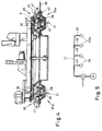
- the section shown in FIG. 4 essentially corresponds to the section according to FIG. 3, vacuum suction elements 35 being provided instead of the electromagnets.
- the vacuum suction elements 35 arranged in the hollow profile 1 are each formed by a circular aluminum plate 36 which has an annular groove 37 on its end face facing the sheet 20, in which an annular sealing element 38 is arranged, and the like. between an O-ring with a diameter of 7 mm in cross-section, which includes an area of 177 cm 2 , and abuts the sheet 20.
- a vacuum line 40 with a diameter of 16 mm connects, which opens into a circular vacuum line 41 with a diameter of also 16 mm, which in turn via a three-way valve, which on the one hand serves to ventilate the cavity 39 and on the other hand connects the cavities 39 with a vacuum pump (not shown) and, as when the current is switched on in the electromagnets, pressures the vacuum suction elements 35 with negative pressure and thus ensures that they are held on the sheet metal.
- the vacuum suction elements 35a which are designed analogously to the other vacuum suction elements 35, hold the support element 42, which essentially corresponds to the armature 26, against the sheet metal 20, vacuum lines 40 and 41 also being provided.
- the vacuum suction elements are connected in parallel.
- FIG. 5 schematically shows a circuit of the vacuum suction elements 35, 35a with the three-way valve V and the vacuum pump P shown.
- the vacuum suction elements 35 are located and 35a via their vacuum lines 40 connected in parallel on the Vacuum line 41, which is connected to the valve V.
- the cavities of the vacuum suction elements 35 or 35a with the atmosphere or with the vacuum pump connected.
- a vacuum pump for the embodiments 5, 6 and 7, a piston pump was used, the was electrically operated.
- the power consumption of the electric motor was 0.55 kW and an average vacuum of up to 20 mbar be preserved.
- the suction power was 200 liters per minute. At 20 mbar, the suction power was still 90% of that at Normal pressure.
- the vacuum pump P is switched on and the cavities are evacuated, whereupon the corresponding cutout is made on the belt, milling work od. Like., Are carried out as required and for Welding certain sheet rounds is inserted, whereby analogous to FIG. 2, the collecting cup 24 or the base 32 can be provided. After completing the work Cavities 39 vented through the valve V so that the devices can easily be lifted off.
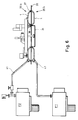
- annular suction elements 35b are provided, which are essentially formed by the annular hollow profiles 1, which are each circular Have grooves 37, in which sealing elements 38, u. between O-rings with a circular cross-section and a diameter of 7 mm.
- the annular vacuum suction elements rest on the sheet metal 20 via these sealing elements 38 and have a volume of 10.1 liters.
- the ring-shaped vacuum suction elements are connected to the vacuum pumps P 1 and P 2 via the vacuum lines 41.
- the lower ring-shaped vacuum suction element 35b either carries, as shown in FIG.
- a collecting cup 24 which can collect any welding beads or the like which may occur as well as milling waste.
- a further central vacuum suction element 35c with a volume of 0.4 liter, 1.0 liter or 2.0 liter, depending on the size of the round blanks to be used, is provided, which holds the lead round plate 31 to be welded in.
- the pad 32 is held by the lower annular vacuum suction element 35b.
- the ring-shaped lower vacuum suction element 35b is connected to its own vacuum pump P 1
- the upper ring-shaped vacuum suction element 35b is connected to the vacuum pump P 2 together with the vacuum suction element 35c via a T-piece, which each has valves V 1 and V 2 .
- valve V 2 is initially opened and the valve V 1 is closed. After the desired vacuum has been reached in the vacuum suction element 35b, the valve V 2 is closed and the valve V 1 is opened, so that the vacuum suction element 35c is evacuated alone.
- the vacuum suction pump can then also be kept in operation, with both valves V 1 and V 2 being open.
- the vacuum suction elements 35b and 35c can also be ventilated by venting the pumps P 1 and P 2 .
- the procedure for cutting, milling and welding round blanks is analogous to that for the device with electromagnets.
- the steels had the following composition: Steel A: Carbon: Max. 0.09% by weight Chrome: 15.0% by weight Nickel: 7.0% by weight Copper: 0.7% by weight Titanium: 0.4% by weight Remainder iron and impurities Steel B: Carbon: Max. 0.03% by weight Chrome: 14.5% by weight Nickel: 4.5% by weight Copper: 3.3% by weight Manganese: 0.75% by weight Silicon: 0.3% by weight Niobium: min. 5 x wt% C Remainder iron and impurities.
- the sheets were each endless belts, that of a double belt press were arranged.
Landscapes
- Engineering & Computer Science (AREA)
- Physics & Mathematics (AREA)
- Mechanical Engineering (AREA)
- Optics & Photonics (AREA)
- Plasma & Fusion (AREA)
- Arc Welding In General (AREA)
- Butt Welding And Welding Of Specific Article (AREA)
- Jigs For Machine Tools (AREA)
- Auxiliary Devices For And Details Of Packaging Control (AREA)
- Perforating, Stamping-Out Or Severing By Means Other Than Cutting (AREA)
- Milling Processes (AREA)
- Press Drives And Press Lines (AREA)
- Treatment Of Fiber Materials (AREA)
- Food-Manufacturing Devices (AREA)
- Replacement Of Web Rolls (AREA)
- Details Of Cutting Devices (AREA)
Applications Claiming Priority (3)
| Application Number | Priority Date | Filing Date | Title |
|---|---|---|---|
| AT1329/96 | 1996-07-23 | ||
| AT132996 | 1996-07-23 | ||
| AT0132996A AT404570B (de) | 1996-07-23 | 1996-07-23 | Vorrichtung zum ausschneiden und einschweissen von blechronden in ein blech |
Publications (2)
| Publication Number | Publication Date |
|---|---|
| EP0820833A1 EP0820833A1 (de) | 1998-01-28 |
| EP0820833B1 true EP0820833B1 (de) | 1999-06-09 |
Family
ID=3511553
Family Applications (1)
| Application Number | Title | Priority Date | Filing Date |
|---|---|---|---|
| EP97890136A Expired - Lifetime EP0820833B1 (de) | 1996-07-23 | 1997-07-14 | Vorrichtung zum Ausschneiden und Einschweissen von Blechronden in ein Blech |
Country Status (12)
| Country | Link |
|---|---|
| US (1) | US6073324A (pt) |
| EP (1) | EP0820833B1 (pt) |
| JP (1) | JPH10100032A (pt) |
| KR (1) | KR980008421A (pt) |
| AT (2) | AT404570B (pt) |
| AU (1) | AU724489B2 (pt) |
| BR (1) | BR9704060A (pt) |
| CA (1) | CA2210942C (pt) |
| DE (1) | DE59700197D1 (pt) |
| ES (1) | ES2134673T3 (pt) |
| ID (1) | ID19181A (pt) |
| MY (1) | MY124110A (pt) |
Families Citing this family (28)
| Publication number | Priority date | Publication date | Assignee | Title |
|---|---|---|---|---|
| AT413679B (de) * | 1999-05-07 | 2006-05-15 | Berndorf Band Ges M B H | Presse mit einem blech und ein blech aus stahl |
| US6352194B1 (en) * | 1999-12-13 | 2002-03-05 | Sandvik Aktiebolag | Method and apparatus for cutting pieces from, and welding pieces into, sheet metal |
| AT411436B (de) * | 2000-02-29 | 2004-01-26 | Berndorf Band Gmbh | Vorrichtung und verfahren zum mechanischen bearbeiten von längsrändern von endlosen bändern |
| KR100705265B1 (ko) * | 2005-12-29 | 2007-04-09 | 주식회사 포스코 | 수동 레이저 용접기의 제품 자동 이송장치 |
| US20080072058A1 (en) * | 2006-08-24 | 2008-03-20 | Yoram Cedar | Methods in a reader for one time password generating device |
| US8157155B2 (en) * | 2008-04-03 | 2012-04-17 | Caterpillar Inc. | Automated assembly and welding of structures |
| CN201455527U (zh) * | 2009-06-30 | 2010-05-12 | 武汉法利普纳泽切割系统有限公司 | 等离子垂直切割枪防碰撞装置 |
| US20150150269A1 (en) * | 2012-08-01 | 2015-06-04 | Frito-Lay North America, Inc. | Continuous process and apparatus for making a pita chip |
| US9199333B2 (en) * | 2013-07-28 | 2015-12-01 | Forge Tech, Inc. | Method for repairing and improving structural integrity of storage tanks |
| CN103817531B (zh) * | 2014-03-07 | 2016-08-24 | 德州晶达节能技术有限公司 | 网架板焊接装置 |
| US20150330449A1 (en) * | 2014-05-15 | 2015-11-19 | Aktiebolaget Skf | Method for manufacturing a rolling bearing and rolling bearing manufactured according to such a method |
| BR112019022687B1 (pt) * | 2017-05-02 | 2023-04-11 | Ipco Sweden Ab | Aparelho para reparar uma chapa de metal e método de operação do aparelho |
| CN107309534A (zh) * | 2017-08-28 | 2017-11-03 | 四川建筑职业技术学院 | 一种采用优化corexy结构的自动化等离子切割机 |
| CN107470909B (zh) * | 2017-09-14 | 2023-08-08 | 中国葛洲坝集团股份有限公司 | 一种压力钢管焊缝自动校平焊接装置及焊接方法 |
| CN109604886B (zh) * | 2018-11-20 | 2023-06-30 | 宁波中和汽配有限公司 | 一种滚针研磨定位盘中限位套的焊接装置 |
| CN111203724A (zh) * | 2020-03-02 | 2020-05-29 | 北京世东凌云科技有限公司 | 一种卡扣安装及毛边削边打磨处理装置 |
| CN112355649B (zh) * | 2020-10-15 | 2021-06-29 | 广州幸永科技有限公司 | 一种高端装备制造用钢块分割抛光设备 |
| CN112621239B (zh) * | 2020-12-09 | 2023-02-10 | 清远楚江高精铜带有限公司 | 一种带毛刺清理的铜带分条机 |
| CN112621252B (zh) * | 2020-12-29 | 2025-10-17 | 信达科创(唐山)石油设备有限公司 | 一种连续油管板板对接焊接设备及焊接方法 |
| CN113290081A (zh) * | 2021-05-25 | 2021-08-24 | 西安石油大学 | 一种h型钢结构翼板矫正机及其使用方法 |
| CN113305581B (zh) * | 2021-06-09 | 2022-04-29 | 南京二机齿轮机床有限公司 | 一种齿轮加工自动生产线 |
| CN115703158A (zh) * | 2021-08-06 | 2023-02-17 | 沈阳富创精密设备股份有限公司 | 一种半导体大型薄板的加工工艺 |
| CN116652598A (zh) * | 2022-02-21 | 2023-08-29 | 惠亚科技(苏州)有限公司 | 加工设备及其运行方法 |
| CN116329951B (zh) * | 2023-04-06 | 2024-02-02 | 威尔斯新材料(太仓)有限公司 | 一种高弹超薄钢带的裁切装置 |
| CN119036085B (zh) * | 2024-08-26 | 2025-03-25 | 上海阜邦幕墙门窗工程有限公司 | 一种用于金属幕墙加工的多功能金属切割设备 |
| CN118809204B (zh) * | 2024-09-18 | 2024-12-06 | 四川合力洁净集团股份有限公司 | 一种金属板材剪切折弯成型一体机及方法 |
| CN119141251B (zh) * | 2024-11-20 | 2025-03-14 | 吉林省翰林净化工程安装有限公司 | 一种便于定位的钢板切割装置 |
| CN119282709B (zh) * | 2024-12-11 | 2025-04-11 | 济宁市兖州区一针电子有限公司 | 一种二极管引线的处理设备 |
Family Cites Families (39)
| Publication number | Priority date | Publication date | Assignee | Title |
|---|---|---|---|---|
| DE223385C (pt) * | ||||
| US1348363A (en) * | 1919-05-05 | 1920-08-03 | Kilts Frank | Oxyacetylene cutting-machine for circular plates |
| US2269505A (en) * | 1940-05-07 | 1942-01-13 | Air Reduction | Circle cutting machine |
| US2504509A (en) * | 1947-10-10 | 1950-04-18 | Gen Motors Corp | Method of repairing damaged sheet metal |
| DE871994C (de) * | 1951-10-02 | 1953-03-26 | Karl Schlichting Jun | Brennmaschine zum Zerschneiden von Eisenblech und Stabeisen |
| US2782488A (en) * | 1954-08-03 | 1957-02-26 | Bliss E W Co | Strip splicer |
| US3188069A (en) * | 1961-12-19 | 1965-06-08 | Joseph F Chiamparino | Flame cutting and beveling machine |
| US3275794A (en) * | 1963-11-06 | 1966-09-27 | Mcdonnell Aircraft Corp | Apparatus for welding sheet material |
| SE306215B (pt) * | 1965-07-05 | 1968-11-18 | Elektriska Svetsnings Ab | |
| US3417979A (en) * | 1965-08-10 | 1968-12-24 | Weld Tooling Corp | Welding or cutting machine with removable template |
| BE697364A (pt) * | 1967-04-21 | 1967-10-02 | ||
| US3569658A (en) * | 1968-04-09 | 1971-03-09 | Teledyne Inc | Apparatus for applying weld metal to the interior surface of a housing for a dredge pump or the like |
| US3614078A (en) * | 1969-10-24 | 1971-10-19 | Ralph M Hepler | Plate-cutting machine and the like |
| US3677656A (en) * | 1971-02-19 | 1972-07-18 | Eugene W Buck | Radial positioner, lock and rotary contacts for electromagnetic drill mount |
| US3941358A (en) * | 1975-04-24 | 1976-03-02 | Darling Lawrence M | Cutting torch guide |
| US4021025A (en) * | 1975-05-08 | 1977-05-03 | Frame Ronald A | Circle cutter |
| US4283617A (en) * | 1976-02-03 | 1981-08-11 | Merrick Welding International, Inc. | Automatic pipe welding system |
| US4049183A (en) * | 1976-05-24 | 1977-09-20 | General Dynamics Corporation | Welding back-up tape |
| US4256288A (en) * | 1979-08-03 | 1981-03-17 | Rojas Miguel E | Hole cutting apparatus |
| US4330110A (en) * | 1980-01-21 | 1982-05-18 | Creech Clyde W | Apparatus and method for cutting holes in steel plates |
| US4303054A (en) * | 1980-05-01 | 1981-12-01 | Lopre Products, Inc. | Detachable magnetic base for machine tool table |
| US4330076A (en) * | 1980-07-22 | 1982-05-18 | Lollis Glen R | Method for replacing bolster rings |
| US4392604A (en) * | 1980-08-27 | 1983-07-12 | The Boeing Company | Panel welding system |
| US4362077A (en) * | 1981-03-09 | 1982-12-07 | Gerber Garment Technology, Inc. | Apparatus for working on sheet material and having magnetic holddown means |
| US4593849A (en) * | 1984-09-24 | 1986-06-10 | Republic Welding Company | Rotary welding device |
| US4687385A (en) * | 1985-04-08 | 1987-08-18 | Milwaukee Electric Tool Corporation | Portable hole cutting power tool |
| US4850579A (en) * | 1986-02-04 | 1989-07-25 | Crest-Foam Corporation | Supporting bed for sheet material cutting machine and method of manufacture |
| SU1666286A1 (ru) * | 1989-01-26 | 1991-07-30 | Одесский Политехнический Институт | Сварочный автомат |
| US5028223A (en) * | 1989-07-31 | 1991-07-02 | Ameter Stephen L | Magnetically attached support device for windshield repair apparatus |
| US5025972A (en) * | 1990-02-06 | 1991-06-25 | Finlan William P | Apparatus for patching a hole in the hull of a moving ship |
| DE4010308C2 (de) * | 1990-03-30 | 1995-04-06 | Dieffenbacher Gmbh Maschf | Kontinuierlich arbeitende Presse |
| DK0451303T3 (da) * | 1990-04-06 | 1993-11-22 | Thyssen Industrie | Fremgangsmåde til sammensvejsning af forskelligt tykke eller lige tykke stålplader i størrelsesordenen fra 0,18 mm til 8 mm ved hjælp af lasersvejsning i en gennemløbsproces og apparat til udøvelse af denne fremgangsmåde |
| NL192672C (nl) * | 1990-11-02 | 1997-12-02 | Atlantic Point Inc | Lassteunring. |
| JPH05177592A (ja) * | 1991-12-25 | 1993-07-20 | Kawakami Seisakusho:Kk | 積層物の裁断装置 |
| US5443199A (en) * | 1993-12-03 | 1995-08-22 | Krumszyn; Luba M. | Universal carriage for cutting and welding |
| US5596917A (en) * | 1994-02-18 | 1997-01-28 | Gerber Garment Technology, Inc. | Apparatus for conveying and cutting sheet material on a vacuum bed with system for sealing end portions of the bed |
| JPH0871791A (ja) * | 1994-09-07 | 1996-03-19 | Hitachi Zosen Corp | 非磁性鋼用自動溶接設備 |
| US5575971A (en) * | 1995-05-04 | 1996-11-19 | Bond; Jerry L. | Circle circumscriber and cutter of steel plates |
| US5836224A (en) * | 1995-12-27 | 1998-11-17 | Gerber Garment Technology, Inc. | Method and apparatus for working on sheet material |
-
1996
- 1996-07-23 AT AT0132996A patent/AT404570B/de not_active IP Right Cessation
-
1997
- 1997-07-14 EP EP97890136A patent/EP0820833B1/de not_active Expired - Lifetime
- 1997-07-14 ES ES97890136T patent/ES2134673T3/es not_active Expired - Lifetime
- 1997-07-14 DE DE59700197T patent/DE59700197D1/de not_active Expired - Fee Related
- 1997-07-14 AT AT97890136T patent/ATE181004T1/de not_active IP Right Cessation
- 1997-07-18 JP JP9225466A patent/JPH10100032A/ja active Pending
- 1997-07-18 CA CA002210942A patent/CA2210942C/en not_active Expired - Fee Related
- 1997-07-21 ID IDP972515A patent/ID19181A/id unknown
- 1997-07-22 KR KR1019970034118A patent/KR980008421A/ko not_active Withdrawn
- 1997-07-22 MY MYPI97003301A patent/MY124110A/en unknown
- 1997-07-23 US US08/899,153 patent/US6073324A/en not_active Expired - Fee Related
- 1997-07-23 AU AU30143/97A patent/AU724489B2/en not_active Ceased
- 1997-07-23 BR BR9704060-6A patent/BR9704060A/pt not_active IP Right Cessation
Also Published As
| Publication number | Publication date |
|---|---|
| JPH10100032A (ja) | 1998-04-21 |
| ATE181004T1 (de) | 1999-06-15 |
| DE59700197D1 (de) | 1999-07-15 |
| ATA132996A (de) | 1998-05-15 |
| MY124110A (en) | 2006-06-30 |
| US6073324A (en) | 2000-06-13 |
| BR9704060A (pt) | 2000-10-17 |
| AU724489B2 (en) | 2000-09-21 |
| EP0820833A1 (de) | 1998-01-28 |
| CA2210942A1 (en) | 1998-01-23 |
| AT404570B (de) | 1998-12-28 |
| ID19181A (id) | 1998-06-28 |
| ES2134673T3 (es) | 1999-10-01 |
| AU3014397A (en) | 1998-01-29 |
| KR980008421A (ko) | 1998-04-30 |
| CA2210942C (en) | 2005-04-12 |
Similar Documents
| Publication | Publication Date | Title |
|---|---|---|
| EP0820833B1 (de) | Vorrichtung zum Ausschneiden und Einschweissen von Blechronden in ein Blech | |
| DE60301090T2 (de) | Vorrichtung zum Stanznieten | |
| CH644046A5 (de) | Vorrichtung zum herstellen von im wesentlichen zylindrischen schiffskoerpersektionen zum bau von unterseebooten. | |
| EP0318966A2 (de) | Maschine zur Oberflächenbearbeitung mit Vorrichtungen zur Positionierung von Bearbeitungswerkzeugen | |
| EP1136179A2 (de) | Adaptives Werkstück-Spann- und Handlingssystem | |
| DE3878602T2 (de) | Ausbesserung von walzwerkwalzen und geraet dafuer. | |
| DE69909977T2 (de) | Vorrichtung zum Stumpf-Laserschweissen von Blechen (vorbestimmten Zuschnitten), die magnetische Rollen hat um die Bleche nach der Schweissposition zu bewegen und die aktive Klemmen hat, um die Bleche zu klemmen | |
| DE10335085B4 (de) | Setzwerkzeug mit auswechselbaren Baugruppen | |
| WO2018055177A1 (de) | Werkzeugmaschine und verfahren zum bearbeiten von plattenförmigen werkstücken | |
| EP1677943A2 (de) | Aufspanntisch mit einer teleskoprohreinheit und einem saugteller aufweisenden spannelement | |
| EP1346792A1 (de) | Schweiss- bzw. Fügeeinheit | |
| DE3442011A1 (de) | Maschine fuer die schleifbearbeitung von werkstuecken, insbesondere fuer die nachbearbeitung von werkzeuge | |
| EP4029661A1 (de) | Greifvorrichtung für einen roboter, die eine prozessvorrichtung umfasst | |
| AT506999A1 (de) | Verfahren und vorrichtung zur reparatur eines schadens an einem metallischen substrat | |
| DE4332663A1 (de) | Rundtischautomat | |
| EP0066004B1 (de) | Ventilstössel | |
| WO2021000976A1 (de) | Vorrichtung zur lösbaren fixierung eines zu bearbeitenden werkstücks, rahmen zur aufnahme mindestens einer derartigen vorrichtung und verfahren zur lagerung des zu bearbeitenden werkstücks | |
| CH668020A5 (de) | Einrichtung zum automatischen werkstueckwechsel in numerisch gesteuerten mehroperationen-werkzeugmaschinen. | |
| DE4441539C1 (de) | Vorrichtung zum lagegerechten Positionieren von Blechplatinen für das Strahlschweißen | |
| DE3240858A1 (de) | Vorrichtung fuer die bearbeitung eines metallischen werkstueckes durch stanzen oder praegen | |
| DE102016119464B4 (de) | Werkzeug und Werkzeugmaschine sowie Verfahren zur Bearbeitung von plattenförmigen Werkstücken | |
| DE3433519C1 (de) | Reibschweißmaschine | |
| DE1527562A1 (de) | Verfahren zur Herstellung metallischer Rahmen gleicher Abmessung | |
| EP0461598A1 (de) | Werkzeugmaschine | |
| DE3113396C2 (pt) |
Legal Events
| Date | Code | Title | Description |
|---|---|---|---|
| PUAI | Public reference made under article 153(3) epc to a published international application that has entered the european phase |
Free format text: ORIGINAL CODE: 0009012 |
|
| AK | Designated contracting states |
Kind code of ref document: A1 Designated state(s): AT BE CH DE DK ES FI FR GB GR IE IT LI LU MC NL PT SE |
|
| AX | Request for extension of the european patent |
Free format text: AL;LT;LV;RO;SI |
|
| 17P | Request for examination filed |
Effective date: 19980721 |
|
| RBV | Designated contracting states (corrected) |
Designated state(s): AT DE ES FR IT SE |
|
| GRAG | Despatch of communication of intention to grant |
Free format text: ORIGINAL CODE: EPIDOS AGRA |
|
| 17Q | First examination report despatched |
Effective date: 19990204 |
|
| GRAG | Despatch of communication of intention to grant |
Free format text: ORIGINAL CODE: EPIDOS AGRA |
|
| GRAH | Despatch of communication of intention to grant a patent |
Free format text: ORIGINAL CODE: EPIDOS IGRA |
|
| GRAH | Despatch of communication of intention to grant a patent |
Free format text: ORIGINAL CODE: EPIDOS IGRA |
|
| GRAA | (expected) grant |
Free format text: ORIGINAL CODE: 0009210 |
|
| AK | Designated contracting states |
Kind code of ref document: B1 Designated state(s): AT BE CH DE ES FR GB IE IT LI LU PT SE |
|
| REF | Corresponds to: |
Ref document number: 181004 Country of ref document: AT Date of ref document: 19990615 Kind code of ref document: T |
|
| REG | Reference to a national code |
Ref country code: CH Ref legal event code: EP |
|
| REF | Corresponds to: |
Ref document number: 59700197 Country of ref document: DE Date of ref document: 19990715 |
|
| ITF | It: translation for a ep patent filed | ||
| REG | Reference to a national code |
Ref country code: IE Ref legal event code: FG4D Free format text: GERMAN |
|
| REG | Reference to a national code |
Ref country code: CH Ref legal event code: NV Representative=s name: BUECHEL, VON REVY & PARTNER |
|
| ET | Fr: translation filed | ||
| GBT | Gb: translation of ep patent filed (gb section 77(6)(a)/1977) |
Effective date: 19990907 |
|
| REG | Reference to a national code |
Ref country code: ES Ref legal event code: FG2A Ref document number: 2134673 Country of ref document: ES Kind code of ref document: T3 |
|
| REG | Reference to a national code |
Ref country code: PT Ref legal event code: SC4A Free format text: AVAILABILITY OF NATIONAL TRANSLATION Effective date: 19990811 |
|
| PLBI | Opposition filed |
Free format text: ORIGINAL CODE: 0009260 |
|
| PLBF | Reply of patent proprietor to notice(s) of opposition |
Free format text: ORIGINAL CODE: EPIDOS OBSO |
|
| 26 | Opposition filed |
Opponent name: SANDVIK AB Effective date: 20000308 |
|
| PLBF | Reply of patent proprietor to notice(s) of opposition |
Free format text: ORIGINAL CODE: EPIDOS OBSO |
|
| PLBO | Opposition rejected |
Free format text: ORIGINAL CODE: EPIDOS REJO |
|
| APAC | Appeal dossier modified |
Free format text: ORIGINAL CODE: EPIDOS NOAPO |
|
| APAE | Appeal reference modified |
Free format text: ORIGINAL CODE: EPIDOS REFNO |
|
| APAC | Appeal dossier modified |
Free format text: ORIGINAL CODE: EPIDOS NOAPO |
|
| PLBN | Opposition rejected |
Free format text: ORIGINAL CODE: 0009273 |
|
| STAA | Information on the status of an ep patent application or granted ep patent |
Free format text: STATUS: OPPOSITION REJECTED |
|
| REG | Reference to a national code |
Ref country code: GB Ref legal event code: IF02 |
|
| 27O | Opposition rejected |
Effective date: 20010131 |
|
| APAH | Appeal reference modified |
Free format text: ORIGINAL CODE: EPIDOSCREFNO |
|
| PGFP | Annual fee paid to national office [announced via postgrant information from national office to epo] |
Ref country code: PT Payment date: 20090622 Year of fee payment: 13 |
|
| PGFP | Annual fee paid to national office [announced via postgrant information from national office to epo] |
Ref country code: IE Payment date: 20090723 Year of fee payment: 13 Ref country code: FR Payment date: 20090716 Year of fee payment: 13 Ref country code: ES Payment date: 20090724 Year of fee payment: 13 |
|
| PGFP | Annual fee paid to national office [announced via postgrant information from national office to epo] |
Ref country code: SE Payment date: 20090715 Year of fee payment: 13 Ref country code: LU Payment date: 20090720 Year of fee payment: 13 Ref country code: GB Payment date: 20090720 Year of fee payment: 13 Ref country code: DE Payment date: 20090722 Year of fee payment: 13 Ref country code: CH Payment date: 20090715 Year of fee payment: 13 Ref country code: AT Payment date: 20090715 Year of fee payment: 13 |
|
| PGFP | Annual fee paid to national office [announced via postgrant information from national office to epo] |
Ref country code: BE Payment date: 20090818 Year of fee payment: 13 |
|
| PGFP | Annual fee paid to national office [announced via postgrant information from national office to epo] |
Ref country code: IT Payment date: 20090725 Year of fee payment: 13 |
|
| REG | Reference to a national code |
Ref country code: PT Ref legal event code: MM4A Free format text: LAPSE DUE TO NON-PAYMENT OF FEES Effective date: 20110114 |
|
| BERE | Be: lapsed |
Owner name: *BERNDORF BAND G.M.B.H. Effective date: 20100731 |
|
| REG | Reference to a national code |
Ref country code: CH Ref legal event code: PL |
|
| GBPC | Gb: european patent ceased through non-payment of renewal fee |
Effective date: 20100714 |
|
| REG | Reference to a national code |
Ref country code: FR Ref legal event code: ST Effective date: 20110331 |
|
| REG | Reference to a national code |
Ref country code: IE Ref legal event code: MM4A |
|
| PG25 | Lapsed in a contracting state [announced via postgrant information from national office to epo] |
Ref country code: CH Free format text: LAPSE BECAUSE OF NON-PAYMENT OF DUE FEES Effective date: 20100731 Ref country code: DE Free format text: LAPSE BECAUSE OF NON-PAYMENT OF DUE FEES Effective date: 20110201 Ref country code: LI Free format text: LAPSE BECAUSE OF NON-PAYMENT OF DUE FEES Effective date: 20100731 |
|
| REG | Reference to a national code |
Ref country code: DE Ref legal event code: R119 Ref document number: 59700197 Country of ref document: DE Effective date: 20110201 |
|
| PG25 | Lapsed in a contracting state [announced via postgrant information from national office to epo] |
Ref country code: FR Free format text: LAPSE BECAUSE OF NON-PAYMENT OF DUE FEES Effective date: 20100802 Ref country code: AT Free format text: LAPSE BECAUSE OF NON-PAYMENT OF DUE FEES Effective date: 20100714 Ref country code: IT Free format text: LAPSE BECAUSE OF NON-PAYMENT OF DUE FEES Effective date: 20100714 Ref country code: PT Free format text: LAPSE BECAUSE OF NON-PAYMENT OF DUE FEES Effective date: 20110114 |
|
| PG25 | Lapsed in a contracting state [announced via postgrant information from national office to epo] |
Ref country code: BE Free format text: LAPSE BECAUSE OF NON-PAYMENT OF DUE FEES Effective date: 20100731 |
|
| PG25 | Lapsed in a contracting state [announced via postgrant information from national office to epo] |
Ref country code: IE Free format text: LAPSE BECAUSE OF NON-PAYMENT OF DUE FEES Effective date: 20100714 Ref country code: GB Free format text: LAPSE BECAUSE OF NON-PAYMENT OF DUE FEES Effective date: 20100714 |
|
| REG | Reference to a national code |
Ref country code: ES Ref legal event code: FD2A Effective date: 20111121 |
|
| PG25 | Lapsed in a contracting state [announced via postgrant information from national office to epo] |
Ref country code: ES Free format text: LAPSE BECAUSE OF NON-PAYMENT OF DUE FEES Effective date: 20100715 |
|
| PG25 | Lapsed in a contracting state [announced via postgrant information from national office to epo] |
Ref country code: LU Free format text: LAPSE BECAUSE OF NON-PAYMENT OF DUE FEES Effective date: 20100714 Ref country code: SE Free format text: LAPSE BECAUSE OF NON-PAYMENT OF DUE FEES Effective date: 20100715 |