EP0820839B1 - Schraub-verfahren und -vorrichtung - Google Patents
Schraub-verfahren und -vorrichtung Download PDFInfo
- Publication number
- EP0820839B1 EP0820839B1 EP97902624A EP97902624A EP0820839B1 EP 0820839 B1 EP0820839 B1 EP 0820839B1 EP 97902624 A EP97902624 A EP 97902624A EP 97902624 A EP97902624 A EP 97902624A EP 0820839 B1 EP0820839 B1 EP 0820839B1
- Authority
- EP
- European Patent Office
- Prior art keywords
- screw
- driver bit
- piston
- compressed air
- cylinder
- Prior art date
- Legal status (The legal status is an assumption and is not a legal conclusion. Google has not performed a legal analysis and makes no representation as to the accuracy of the status listed.)
- Expired - Lifetime
Links
Images



Classifications
-
- B—PERFORMING OPERATIONS; TRANSPORTING
- B25—HAND TOOLS; PORTABLE POWER-DRIVEN TOOLS; MANIPULATORS
- B25B—TOOLS OR BENCH DEVICES NOT OTHERWISE PROVIDED FOR, FOR FASTENING, CONNECTING, DISENGAGING, OR HOLDING
- B25B21/00—Portable power-driven screw or nut setting or loosening tools; Attachments for drilling apparatus serving the same purpose
- B25B21/02—Portable power-driven screw or nut setting or loosening tools; Attachments for drilling apparatus serving the same purpose with means for imparting impact to screwdriver blade or nut socket
- B25B21/023—Portable power-driven screw or nut setting or loosening tools; Attachments for drilling apparatus serving the same purpose with means for imparting impact to screwdriver blade or nut socket for imparting an axial impact, e.g. for self-tapping screws
-
- B—PERFORMING OPERATIONS; TRANSPORTING
- B25—HAND TOOLS; PORTABLE POWER-DRIVEN TOOLS; MANIPULATORS
- B25B—TOOLS OR BENCH DEVICES NOT OTHERWISE PROVIDED FOR, FOR FASTENING, CONNECTING, DISENGAGING, OR HOLDING
- B25B21/00—Portable power-driven screw or nut setting or loosening tools; Attachments for drilling apparatus serving the same purpose
-
- B—PERFORMING OPERATIONS; TRANSPORTING
- B25—HAND TOOLS; PORTABLE POWER-DRIVEN TOOLS; MANIPULATORS
- B25B—TOOLS OR BENCH DEVICES NOT OTHERWISE PROVIDED FOR, FOR FASTENING, CONNECTING, DISENGAGING, OR HOLDING
- B25B23/00—Details of, or accessories for, spanners, wrenches, screwdrivers
- B25B23/02—Arrangements for handling screws or nuts
- B25B23/04—Arrangements for handling screws or nuts for feeding screws or nuts
- B25B23/045—Arrangements for handling screws or nuts for feeding screws or nuts using disposable strips or discs carrying the screws or nuts
Definitions
- the present invention relates to screw driving method and apparatus wherein the tip of a driver bit is fitted into the groove of the head of a screw, the fitted screw is disengaged from a screw carrier strip by a forward stroke force of the driver bit, the tip of the screw is driven to a predetermined depth in a workpiece, and the screw is screwed by rotating the driver bit.
- JP-A-7-171770 An apparatus for fitting the tip of a driver bit into the groove on the head of a screw, disengaging the fitted screw from a screw carrier strip by a forward stroke force of the driver bit and driving the screw into a workpiece while rotating the driving bit is publicly known as Japanese Patent Laid-Open No. 7-171770 (JP-A-7-171770).
- JP-A-7-171770 In this screw driving apparatus, in order to solve the problem such a reaction that the driving apparatus is raised when the screw pressed against the workpiece is driven, a moving piston for advancing a driver bit is connected through a spring to the driver bit. The piston can move forward in the way that it compresses the spring even when the driver bit abuts against the workpiece to resist further advance, thereby it preventing the reaction in the direction that the apparatus tends to be raised.
- JP-A-7-171770 causes additional reaction if a strong spring to meet a strong pressing force is used for high-speed pressing and high-speed driving of screws because a greater pressing force is required for screwing them in after they abut against the workpiece.
- a weak spring decreases the speed of pressing screws to slow the driving operation. It is also feared that failure in disengaging screws from a screw carrier strip or in fitting of the tip of the driver bit into the groove on the screw head may arise to hinder the driving operation.
- the present invention aims to provide a screw driving method which is capable of driving screws reliably with less reaction and at a high speed.
- Another object of the invention is to provide a screw driving apparatus which is capable of driving screws reliably with less reaction and at a high speed.
- the inventor of the present invention analyzes by experiments that in the screw driving apparatus, a strong pressing force of 70N to 100 N is required during the period between disengaging a screw from the screw carrier strip and driving the tip of the screw to a predetermined depth in a workpiece, and then a weak pressing force of about 20N or 30N is sufficient when the screw being rotated is screwed into the workpiece. This is because after the screw has been driven into the workpiece to a certain extent, further applying a pressing force of the same strength causes the screw to be driven in like a nail, not to be properly screwed in, so that a sufficient pulling resistance as required of the screw is not obtained.
- the present invention provides a screw driving method comprising steps of fitting the tip of a driver bit into the groove on a screw head, disengaging the fitted screw from a screw carrier strip under a forward stroke force of the driver bit, driving the tip of the screw to a predetermined depth in a workpiece, and screwing the screw in while rotating the driver bit; characterized in that the screw driving method comprises: steps of driving a primary piston of a large diameter together with a secondary piston of a small diameter which reciprocatingly passes through the primary piston, so as to advance the driver bit with a strong pressing force by the primary piston during a period between the step of fitting the tip of the driver bit into the groove on the screw head and the step of driving the tip of the screw to the predetermined depth in the workpiece; and when the screw is screwed into the workpiece after the driving of the screw into the workpiece, stopping advance of the primary piston and advancing the driver bit with a weak pressing force by only the secondary piston which is continuously advanced.
- the present invention also provides a screw driving apparatus which has a cylinder, piston means reciprocating in the cylinder by means of compressed air, a driver bit driven by said pistons, and an air motor to rotate the driver bit, wherein the tip of the driver bit is fitted into the groove on the head of a screw, the fitted screw is disengaged from a screw carrier strip by means of a forward stroke force of the driver bit, the tip of the screw is driven to a predetermined depth in a workpiece and the screw is screwed into the workpiece by the rotating driver bit;
- said piston means comprise: a hollow primary piston capable of reciprocating axially with respect to the cylinder in contact with the inner wall of the cylinder; and a secondary piston capable of reciprocating in the primary piston and piercing through the hollow portion of the primary piston axially with respect to the cylinder; and said secondary piston is integrally connected to the driver bit through the air motor with said secondary piston having a compressed air passage formed to feed the compressed air from the cylinder to the air motor; the primary piston has a compressed
- the primary piston advances the driver bit with a strong pressing force during the period from the fitting of the tip of the driver bit into the groove of the screw head to the driving of the tip of the screw to a predetermined depth in the workpiece, and then screwing-in of the screw is carried out by the rotation of the driver bit which is advanced with a weak pressing force by the secondary piston.
- This makes it possible to drive the screw at a high speed until the tip of the screw is driven to a predetermined depth in the workpiece, and a weak pressing force of about 20-30 N is used to screw the screw in, resulting in reliable screwing-in of the screw and reducing reaction on the apparatus.
- an opening for compressed air to pass through is formed in an upper portion of the secondary piston.
- the opening remains closed when the secondary piston is in its stationary position, but when the secondary piston is advanced, compressed air in the cylinder is fed through the opening to the air motor.
- movement of the secondary piston is synchronized with the rotation of the driver bit.
- Fig. 1 is a sectional view showing a screw driving apparatus according to the present invention in its stationary position.
- Fig. 2 is a sectional view taken along the line A - A of the screw driving apparatus of Fig. 1.
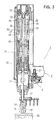
- Fig. 3 is a sectional view of an initial stage of driving operation of the screw driving apparatus according to the present invention.
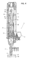
- Fig. 4 is a sectional view showing the screw driving apparatus in which the tip of a screw has been driven to a predetermined depth in a workpiece.
- Fig. 5 is a sectional view of the screw driving apparatus in which screwing operation has just been completed.
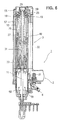
- Fig. 6 is a sectional view of the screw driving apparatus returned to the stationary position by releasing the trigger lever.
- a screw driving apparatus 1 according to the present invention is shown in the state before starting its screw driving operation, that is, in its stationary state.
- the screw driving apparatus 1 comprises a handle 2 and a body 3.
- the handle 2 is provided with a trigger device 5 for actuating driving operation, and the screw driving apparatus is actuated when a trigger lever 6 is triggered.
- a trigger lever 6 To an end 7 of the handle 2 compressed air is fed and the hollow portions of the handle 2 and the body 3 are filled with compressed air as shown by arrows 9 and the hollows portions serve as reservoirs of compressed air.
- the handle 2 can be adapted to hold a magazine (not shown) to contain a coiled screw carrier strip.
- the body 3 is provided with a cylinder 10 extending vertically to cover substantially the overall length of the body. Inside the cylinder 10, means to move a driver bit 11 vertically and means to rotate the driver bit are provided. Details of these means are described later.
- the body 3 is provided with a nose 15 in which a plurality of screws 14 removably held by a carrier strip 13 are placed.
- the nose 15 is provided with a feeder 17 to guide the screw carrier strip 13, which the feeder serves so that each screw 14 can be positioned on the axis of the driver bit 11.
- the end of the nose 15 is attached with a chuck 18 which enables the screw 14 disengaged from the carrier strip to be kept in its proper position and to be pressed by downward movement i.e., a forward stroke, of the driver.
- the lower end of the chuck 18 is biased by an O-ring in the direction in which it is closed and the chuck keeps the screw 14 in the proper position and guides it smoothly in the direction of driving.
- a main valve 19 is positioned on upper portion of the cylinder 10 of the body 3 to control feeding of compressed air to the cylinder 10.
- the main valve 19 moves between a lower stationary position (the position shown in Fig. 1) in which it stops the feed of compressed air from the reservoir to the cylinder 10 and an upper driving position (the position shown in Figs. 4 through 6) in which compressed air is fed to an upper portion of the cylinder 10.
- the returned position shown in Fig. 6 is the same as the stationary position in Fig. 1.
- the main valve 19 is controlled by the trigger device 5.
- compressed air in the reservoir of the handle 2 is fed through a trigger valve 21 to a passage 22 (shown by broken lines in Fig. 1) formed in the body and the compressed air which has passed through the passage 22 is fed to a main valve chamber 23 above the main valve 19.
- the compressed air being fed to the main valve chamber 23 presses the main valve 19 down to the stationary position.
- the trigger valve 21 discontinues feeding of compressed air to the passage 22, and then, the compressed air of the main valve chamber 23 passes through the passage 22 and the trigger valve 21, and is discharged from a point close to the trigger lever 5 to the atmosphere.
- the discharge of the compressed air reduces the pressure in the main valve chamber 23 so that the force pressing the main valve 19 is no longer present.
- compressed air from a reservoir 25 of the body 3 works on the bottom surface of the main valve 19 and moves the main valve 19 from the stationary position to the upper driving position. By this movement, the main valve 19 leaves the top of the cylinder 10 open for compressed air to be fed from the reservoir 25. Since the relation between the main valve and the trigger device 5 is the same as in publicly known nail driving apparatuses, further description is omitted.
- the driver bit 11 is reciprocated by pistons which are moved vertically, i.e., reciprocated in the cylinder 10 by means of compressed air.
- pistons which are moved vertically, i.e., reciprocated in the cylinder 10 by means of compressed air.
- the area for receiving the pressure of compressed air on the top of the primary piston 26 is formed so as to be larger than that of the secondary piston 27.
- the primary piston 26 descends more powerfully and at a higher speed than the secondary piston 27, which descends slowly with a weak pressing force.
- the secondary piston 27 extends over the top of the primary piston and an upper portion of the secondary piston 27 reciprocates vertically inside a secondary cylinder 29 on which the inner side of the main valve 19 slides.
- the secondary piston 27 extends through the primary piston 26.
- An air motor 31 as means to rotate the driver bit 11 is attached to a lower portion of the secondary piston.
- the air motor 31 comprises, for example, the so-called vane motor as described, for example, in the Japanese Patent Laid-Open No. 7-171770 (JP-A-7-171770) and it is formed so as to move as a unit, together with the secondary piston 27, inside the cylinder 10.
- a planetary gear type reduction gear 33 is attached as a part of the unit, integrally with the air motor 31.
- the driver bit 11 is the output shaft of the reduction gear 33.
- Fig. 2 is a cross sectional view of the planetary reduction gear 33.
- a shaft 34 functions as a sun gear and two planetary gears 35 to rotate round it are provided.
- An internal gear 37 is fixed to the outer sides of the planetary gears 35. Since the internal gear 37 is fixed, the planetary gears 35 are made to rotate on their own axes by the rotation of the shaft 34 and make orbital motions round the shaft 34.
- the orbital motions are transmitted to rotary discs 39 (Fig. 1) connected to the upper and lower ends of the shaft 38 of each planetary gear 35.
- the driver bit 11 connected to the lower rotary disc 39 rotates at a low speed so as to obtain a predetermined speed of revolution and torque from the shaft 34 of the air motor 31.
- Compressed air is supplied from the reservoir 25 to the air motor 31 to rotate the shaft 34.
- the secondary piston 27 is formed with an axial hole which defines a compressed air passage 41 for feeding compressed air in the cylinder 10 to the air motor 31.
- the compressed air fed through the compressed air passage 41 hits on vanes 43 through intake ports 42 and rotates the shaft 34. Then, the compressed air is discharged outside the body 3 through discharge ports 45.
- a lower portion 46 of the secondary piston 27 has a larger diameter than the lower portion of the primary piston 26 so that the secondary piston 27 is forced to move forward by the advance of the primary piston 26.
- the lower portion 46 of the secondary piston 27 is connected to a housing 47 which surrounds the outer sides of the air motor 31 and the planetary reduction gear 33. Further, a lower portion of the housing 47 is connected to an upper portion of the driver bit 11 rotatably but axially unmovably.
- the length of the primary piston 26 is determined so as to move by a predetermined stroke length. In its stationary position, movement of the primary piston 26 is limited to prevent the piston from going beyond the upper end of the cylinder 10 and also to prevent it from descending below the lowermost driving position (see Fig. 4) by a small diameter portion or stop portion 49 formed at a mid-height of the cylinder 10. Above the stop portion 49, a bumper 50 is provided to reduce impact caused when the primary piston 26 stops advancing.
- the stroke length of the primary piston 26 is determined so that the tip of the driver bit 11 stays above the screw 14 in the nose 15 in the upper stationary position, and at the lowermost driving position (Fig.
- the tip of the driver bit 11 drives the tip of the screw 14 into a predetermined depth in the workpiece (in the illustrated example, it is driven until an attachment member 61 such as a gypsum board on the upper side is penetrated). Therefore, when the primary piston 26 moves from the upper stationary position to the lower driving position, the driver bit 11 is forwardly moved together with the secondary piston 27 by the length of that stroke, and in the position shown in Fig. 4, the driver bit 11 drives the screw 14 to the predetermined depth in the workpiece (61 and 62).
- the secondary piston 27 is longer than the primary piston 26 and has a longer stroke than the primary piston 26. Accordingly, the secondary piston 27 staying in the most advanced position where the screw abuts against the workpiece can advance to reach the position of Fig. 5 where it completes driving by rotating the screw to screw it in.
- feeding of compressed air through the compressed air passage 41 of the secondary piston 27 to the air motor 31 is discontinued to stop the rotation of the driver bit 11.
- the upper end of the secondary piston 27 is provided with an O-ring 51 which seals the hollow portion of the primary piston 26.
- An opening 53 serving as a supply port for the compressed air passage 41 is formed below the O-ring 51 and the top surface of the secondary piston 27 remains closed.
- releasing the trigger lever 6 returns the driver bit 11, the planetary reduction gear 33, the air motor 31, the secondary piston 27 and the primary piston 26 to the stationary positions shown in Figs. 1 and 6.
- a certain number of holes 54 are formed circumferentially at the upper end of the secondary cylinder 29 provided above the cylinder 10, and a resilient O-ring 55 provided to close the holes 54 from outside forms a check valve 55.
- the compressed air which passes through the check valve 55 is fed to a lower portion of the cylinder 10 through a return discharge path 57 extending downwardly on a side of the body 3.
- a hole 58 is formed and compressed air from the return discharge path 57 is sent below the reduction gear 33.
- the secondary cylinder 29 above the cylinder 10 is provided with, at a position separated from the check valve 55, a compressed air escape hole 59 for reducing pressure so as to return the upper end of the secondary piston 27 to the secondary cylinder 29.
- the compressed air escape hole 59 has a small diameter which is just enough to discharge compressed air to the atmosphere little by little without affecting the driving operation by means of compressed air.
- the driver bit 11, the planetary reduction gear 33, the air motor 31, the secondary piston 27 and the primary piston 26 are pressed upward by the check valve 55, the return discharge path 57, the hole 58 in the lower portion of the cylinder and the compressed air return hole 59 and return to their stationary positions. Their return motions are further described later.
- the operation of the screw driving apparatus 1 is described in the following.
- Compressed air is fed from a compressor or the like to the port at the end 7 of the handle 2 to fill the reservoir in the handle 2 and the reservoir 25 in the body 3.
- the trigger is not pulled in the stationary state.
- Compressed air is fed to the main valve chamber through the trigger valve 21 and the passage 22.
- the main valve 19 is in the lower stationary position to close the upper end of the cylinder 10. Since compressed air is not fed to the cylinder 10, the primary piston 26 and the secondary piston 27 are in their upper stationary positions.
- the air motor 31 does not operate with the driver bit 11 also staying in the upper stationary position.
- triggering of the trigger lever 6 allows the compressed air in the main valve chamber 23 to be discharged through the passage 22 and the trigger valve 21, leaving no pressing force on the main valve 19. Since the compressed air in the reservoir 25 always works on the lower periphery of the main valve 19 to push up the main valve 19, the main valve is pressed upward. Once the main valve 19 is pushed up, the upper end of the cylinder 10 is opened. The compressed air in the reservoir 25 is fed to the cylinder and acts on the top surface of the primary piston 26 to press down the primary piston 26. When the primary piston 26 is pressed down as shown in Fig. 3, the lower portion 46 of the secondary piston 27 is pushed down by the primary piston 26.
- the secondary piston 27, the air motor 31, the planetary reduction gear 33 and the driver bit 11 are pressed down.
- the opening 53 of the secondary piston 27 opens.
- the compressed air is fed through the opening 53 and the compressed air passage 41 to the air motor 31, which then begins to be rotated.
- the rotation of the motor is transmitted via the reduction gear 33 to the driver bit 11 and makes the driver bit 11 to be rotated.
- the rotation of the driver bit 11 is synchronized with the downward movement of the secondary piston 27 which lowers the driver bit.
- the strong pressing force by the primary piston 26 in its upper stationary position is maintained during the period including the steps of fitting the tip of the driver bit 11 into the head groove of the screw 14, detaching the screw 14 from the carrier strip 13, and advancing the driver bit still fitted in the screw 14.
- the strong pressing force is kept up to or around the time of piercing the tip of the screw through the attachment member 61 so as to reach another attachment member 62 beneath it as shown in Fig. 4.
- the screw is driven to a predetermined depth in the workpiece which comprises the attachment member 61 such as a gypsum board and the member 62 such as a wooden material.
- Fig. 5 shows the state of the completion of the driving.
- the driver bit 11 is advanced with a strong pressing force by the primary piston 26 until the screw is driven to the predetermined depth, at which its tip abuts against the member 62 or workpiece after piercing through the attachment member 61.
- the advance of the primary piston 26 is stopped.
- the screw being rotated is screwed into the member 62.
- the driver bit 11 is advanced by a weak pressing force of only the secondary piston 27. Therefore, the reaction that the driver bit is raised, which is produced when the screw 14 is screwed into the member 62, is reduced a lot or substantially eliminated.
- the screw is functioned effectively so as to be screwed in reliably.
- the time required for the entire driving can be shortened as a strong pressing force by the primary piston 26 is used until the screw is driven to a predetermined depth in the workpiece.
- the compressed air in the return discharge path 57 is sent below the planetary type reduction gear 33 through the hole 58 in the lower portion of the cylinder 10.
- the compressed air acts to push up the reduction gear 33 together with the air motor 31 and the secondary piston 27.
- the pressure in the upper portion of the cylinder 10 decreases to a level below the pressure which presses up the reduction gear 33
- the reduction gear 33, the air motor 31 and the secondary piston 27 are pushed up.
- the air above the secondary piston 27 is partially discharged to the atmosphere via the compressed air escape hole 59 and the rest is sent through the check valve 55, the return discharge path 57 and the holes 58 to the cylinder below the planetary reduction gear 33.
- This air feeding maintains a higher pressure in the lower portion of the cylinder 10 than in the upper portion of it so as to push up the driver bit 11, the planetary reduction gear 33, the air motor 31 and the secondary piston 27.
- the large-diameter lower portion of the secondary piston 27 comes into engagement with the primary piston 26 to press up the primary piston 26 so that the apparatus returning to the stationary position shown in Figs. 6 and 1.
- the screw can be driven at a high speed with a strong pressing force by the primary piston, and then screwing-in is carried out with a weak pressing force of about 20 N to 30 N.
- a weak pressing force of about 20 N to 30 N.
Landscapes
- Engineering & Computer Science (AREA)
- Mechanical Engineering (AREA)
- Portable Nailing Machines And Staplers (AREA)
- Details Of Spanners, Wrenches, And Screw Drivers And Accessories (AREA)
- Press Drives And Press Lines (AREA)
- Seeds, Soups, And Other Foods (AREA)
Claims (4)
- Schraubendrehverfahren, welches die Schritte des Einsetzens der Spitze eines Schraubendrehereinsatzes (11) in den Schlitz auf einem Schraubenkopf (14), das Lösen der so versehenen Schraube (14) von einem Schraubenträgerstreifen (13) unter einer Vorwärtshubkraft des Schraubendrehereinsatzes (11), das Eintreiben der Spitze der Schraube auf eine vorbestimmte Tiefe in ein Werkstück (61, 62) und das Einschrauben der Schraube bei gleichzeitiger Drehung des Schraubendrehereinsatzes (11) umfasst, dadurch gekennzeichnet, dass das Schraubendrehverfahren Folgendes umfasst: die Schrittedes Antreibens eines Primärkolbens (26) großen Durchmessers zusammen mit einem Sekundärkolben (27) kleinen Durchmessers, welcher sich durch den Primärkolben (26) hin- und herbewegt, so dass während eines Zeitraums zwischen dem Schritt des Einsetzens der Spitze des Schraubendrehereinsatzes (11) in den Schlitz auf dem Schraubenkopf(14) und dem Schritt des Eintreibens der Spitze der Schraube auf die vorbestimmte Tiefe in das Werkstück (61, 62) der Schraubendrehereinsatz (11) durch den Primärkolben (26) mit einer starken Presskraft vorbewegt wird, sowienach Einschrauben der Schraube in das Werkstück (61, 62) nach dem Eintreiben der Schraube in das Werkstück das Anhalten der Vorbewegung des Primärkolbens (26) und das Vorbewegen des Schraubendrehereinsatzes (11) mit einer geringen Presskraft allein durch den Sekundärkolben (27), der kontinuierlich vorbewegt wird.
- Schraubendrehvorrichtung (1), welche einen Zylinder (10), ein in dem Zylinder mittels Druckluft sich hin- und herbewegendes Kolbenmittel (26, 27), einen durch besagte Kolben (26, 27) angetriebenen Schraubendrehereinsatz (11) und einen Druckluftmotor (31) zum Drehen des Schraubendrehereinsatzes umfasst, dadurch gekennzeichnet, dass die Spitze des Schraubendrehereinsatzes in den Schlitz auf dem Kopf einer Schraube (14) gesetzt wird, die so versehene Schraube mittels einer Vorwärtshubkraft des Schraubendrehereinsatzes (11) von einem Schraubenträgerstreifen (13) gelöst wird, die Spitze der Schraube auf eine vorbestimmte Tiefe in ein Werkstück (61, 62) getrieben wird und die Schraube durch das Drehen des Schraubendrehereinsatzes (11) in das Werkstück geschraubt wird, dadurch gekennzeichnet, dass das besagte Kolbenmittel Folgendes umfasst: einen hohlen Primärkolben (26), der in Berührung mit der Innenwand des Zylinders sich bezüglich des Zylinders (10) axial hin- und herbewegen kann, und einen Sekundärkolben (27), der sich in dem Primärkolben (26) hin- und herbewegen und bezüglich des Zylinders (10) axial durch den hohlen Abschnitt des Primärkolben (26) dringen kann; und dass der besagte Sekundärkolben (27) durch den Druckluftmotor (31) mit dem Schraubendrehereinsatz (11) integral verbunden ist, wobei der besagte Sekundärkolben eine Druckluftleitung (41) aufweist, die zur Zufuhr von Druckluft vom Zylinder (10) zu dem Druckluftmotor (31) ausgebildet ist; dass der Primärkolben (26) einen Druckluftdruckaufnahmebereich aufweist, der größer als der Druckaufnahmebereich des Sekundärkolben ist; dass die Vorrichtung (1) zur Vorbewegung des Schraubendrehereinsatzes (11) mit starker Presskraft des Primärkolbens (26) in den vorbewegten Primär- und Sekundärkolben (26, 27) während eines Zeitraums, da die Spitze des Schraubendrehereinsatzes (11) in den Schlitz auf dem Schraubenkopf (14) eingesetzt wird und die Spitze der Schraube dann auf die vorbestimmte Tiefe in das Werkstück (61, 62) getrieben wird, ausgelegt ist; und dass die Vorrichtung (1) weiterhin Mittel (49) zum Anhalten der Vorbewegung des Primärkolbens (26) nach dem Eintreiben der Schraube in das Werkstück (61, 62) aufweist, so dass der Schraubendrehereinsatz mit einer geringen Presskraft, die von dem weiter vorbewegten Sekundärkolben (27) allein ausgeübt wird, vorbewegt werden kann.
- Vorrichtung (1) nach Anspruch 2, dadurch gekennzeichnet, dass eine Öffnung (53) für die Druckluftleitung (41) in einem oberen Bereich des Sekundärkolbens (27) ausgebildet ist und die Öffnung geschlossen bleibt, wenn sich der Sekundärkolben in seiner Ruhestellung befindet, aber die Druckluft in dem Zylinder (10) durch die Öffnung (53) dem Druckluftmotor (31) zugeführt wird, wenn der Sekundärkolben (27) vorbewegt wird.
- Vorrichtung (1) nach Anspruch 3, welche weiterhin Mittel (51) zum Unterbrechen der Zufuhr von Druckluft zu dem Druckluftmotor (31) durch Abdichten der Druckluftleitung (41) in dem Sekundärkolben (27), sobald der Sekundärkolben die vorgerückteste Position erreicht, in der das Eintreiben der Schraube beendet ist, umfasst.
Applications Claiming Priority (4)
| Application Number | Priority Date | Filing Date | Title |
|---|---|---|---|
| JP24267/96 | 1996-02-09 | ||
| JP02426796A JP3793272B2 (ja) | 1996-02-09 | 1996-02-09 | ねじ打込方法及び装置 |
| JP2426796 | 1996-02-09 | ||
| PCT/JP1997/000324 WO1997028927A1 (fr) | 1996-02-09 | 1997-02-07 | Procede et dispositif pour visser une vis |
Publications (3)
| Publication Number | Publication Date |
|---|---|
| EP0820839A1 EP0820839A1 (de) | 1998-01-28 |
| EP0820839A4 EP0820839A4 (de) | 1998-04-22 |
| EP0820839B1 true EP0820839B1 (de) | 2000-10-18 |
Family
ID=12133459
Family Applications (1)
| Application Number | Title | Priority Date | Filing Date |
|---|---|---|---|
| EP97902624A Expired - Lifetime EP0820839B1 (de) | 1996-02-09 | 1997-02-07 | Schraub-verfahren und -vorrichtung |
Country Status (8)
| Country | Link |
|---|---|
| US (1) | US5862724A (de) |
| EP (1) | EP0820839B1 (de) |
| JP (1) | JP3793272B2 (de) |
| AU (1) | AU696134B2 (de) |
| CA (1) | CA2217685C (de) |
| DE (1) | DE69703319T2 (de) |
| ES (1) | ES2151243T3 (de) |
| WO (1) | WO1997028927A1 (de) |
Families Citing this family (28)
| Publication number | Priority date | Publication date | Assignee | Title |
|---|---|---|---|---|
| US6026713A (en) * | 1997-07-04 | 2000-02-22 | Hitachi Koki Co., Ltd. | Pneumatically operated screw driver |
| US6062113A (en) * | 1998-03-16 | 2000-05-16 | Hitachi Koki Co., Ltd. | Pneumatically operated screw driver having mechanism for assisting separation of screw from screw band |
| JP3744197B2 (ja) * | 1998-04-22 | 2006-02-08 | 日立工機株式会社 | 圧縮空気ねじ締め機 |
| GB9810746D0 (en) * | 1998-05-19 | 1998-07-15 | Multi Automation Limited | Fastening apparatus |
| US6138536A (en) * | 1999-03-29 | 2000-10-31 | Chen; Sen-Yang | Screw driving gun with a screw orientation guide member |
| WO2000078509A1 (en) * | 1999-06-17 | 2000-12-28 | Babij Alex Jr | A screw guide |
| KR100545408B1 (ko) * | 2000-10-18 | 2006-01-24 | 마크스 가부시기가이샤 | 공기충격식 드라이버 |
| JP2002355766A (ja) * | 2001-06-01 | 2002-12-10 | Max Co Ltd | 圧縮空気駆動ネジ締め機 |
| JP3965944B2 (ja) * | 2001-07-13 | 2007-08-29 | 日立工機株式会社 | ねじ締め機 |
| DE10137896A1 (de) * | 2001-08-02 | 2003-02-20 | Paul-Heinz Wagner | Verfahren zur Steuerung eines intermittierend arbeitenden Schraubwerkzeugs |
| EP1459849B1 (de) * | 2001-08-08 | 2011-12-21 | Max Co., Ltd. | Sicherheitsvorrichtung für druckluftschlagschrauber |
| US7134367B2 (en) * | 2002-12-09 | 2006-11-14 | Milwaukee Electric Tool Corporation | Fastener feeding system |
| US20050061522A1 (en) * | 2003-09-22 | 2005-03-24 | Yun-Chung Lee | Piston rod rotary driving device of screw nail gun |
| US6843400B1 (en) * | 2003-09-22 | 2005-01-18 | Yun-Chung Lee | Pneumatic motor driving valve of screw nail gun |
| US7165478B2 (en) * | 2003-10-01 | 2007-01-23 | Hitachi Koki Co., Ltd. | Pneumatically operated screw driver |
| US20050098333A1 (en) * | 2003-11-12 | 2005-05-12 | Yun-Chung Lee | Air valve of pneumatic motor of screwdriver and air path of the air valve |
| US6942042B2 (en) * | 2003-11-12 | 2005-09-13 | De Poan Pneamatic Corp. | Pneumatic motor-controlled valve of screwdriver |
| WO2008085465A2 (en) | 2006-12-29 | 2008-07-17 | Illinois Tool Works Inc. | Cordless fastener tool with fastener driving and rotating functions |
| DE112008000558T5 (de) | 2007-03-02 | 2010-01-07 | Biomet Microfixation, LLC, Jacksonville | Verfahren zum Einsetzen eines Befestigungselements |
| JP5097416B2 (ja) * | 2007-03-06 | 2012-12-12 | 株式会社マキタ | ねじ打ち込み機 |
| US7802500B2 (en) * | 2007-12-26 | 2010-09-28 | Illinois Tool Works, Inc. | Pneumatic fastener driving tool |
| JP5112043B2 (ja) * | 2007-12-27 | 2013-01-09 | 株式会社マキタ | ねじ打ち込み機 |
| IT1395788B1 (it) * | 2009-09-16 | 2012-10-19 | Fiam Utensili Pneumatici | Dispositivo per l'applicazione di inserti. |
| US20140014703A1 (en) | 2012-07-10 | 2014-01-16 | Illinois Tool Works Inc. | Fastener driving tool with fastener driving and rotating mechanism |
| DE102014106476A1 (de) * | 2014-05-08 | 2015-11-12 | Weber Schraubautomaten Gmbh | Schraubsystem |
| CN105033923B (zh) * | 2015-08-21 | 2017-05-31 | 东莞市精心自动化设备科技有限公司 | 一种手持式锁螺钉工具及含有该工具的送锁螺钉机 |
| WO2018062609A1 (ko) * | 2016-09-28 | 2018-04-05 | 계양전기 주식회사 | 전동 공구의 툴 어셈블리 및 이를 포함하는 전동 공구 |
| CN107127706B (zh) * | 2017-05-04 | 2018-11-02 | 资义勇 | 气动螺钉枪 |
Family Cites Families (7)
| Publication number | Priority date | Publication date | Assignee | Title |
|---|---|---|---|---|
| US2383380A (en) * | 1944-04-25 | 1945-08-21 | Gimpel Karl | Pneumatic punch |
| JPS61257784A (ja) * | 1985-05-09 | 1986-11-15 | 川島 正樹 | 打込みネジ用装着工具 |
| JPS6445581A (en) * | 1987-08-08 | 1989-02-20 | Hitachi Koki Kk | Air screw driver |
| IT1216607B (it) * | 1988-04-20 | 1990-03-08 | Mario Zucchelli | Macchina automatica autoavanzante per l'applicazione di inserti. |
| US5231902A (en) * | 1991-06-10 | 1993-08-03 | Hitachi Koki Co. Ltd. | Pneumatically operated screw driver |
| JP3248299B2 (ja) * | 1993-05-07 | 2002-01-21 | 日立工機株式会社 | 圧縮空気ねじ締機 |
| JP3561283B2 (ja) * | 1993-12-17 | 2004-09-02 | 日立工機株式会社 | 圧縮空気ねじ締め機の反動低減機構 |
-
1996
- 1996-02-09 JP JP02426796A patent/JP3793272B2/ja not_active Expired - Lifetime
-
1997
- 1997-02-07 DE DE69703319T patent/DE69703319T2/de not_active Expired - Lifetime
- 1997-02-07 US US08/930,985 patent/US5862724A/en not_active Expired - Lifetime
- 1997-02-07 WO PCT/JP1997/000324 patent/WO1997028927A1/ja not_active Ceased
- 1997-02-07 ES ES97902624T patent/ES2151243T3/es not_active Expired - Lifetime
- 1997-02-07 EP EP97902624A patent/EP0820839B1/de not_active Expired - Lifetime
- 1997-02-07 AU AU16704/97A patent/AU696134B2/en not_active Expired
- 1997-02-07 CA CA002217685A patent/CA2217685C/en not_active Expired - Fee Related
Also Published As
| Publication number | Publication date |
|---|---|
| JP3793272B2 (ja) | 2006-07-05 |
| DE69703319T2 (de) | 2001-02-22 |
| JPH09216170A (ja) | 1997-08-19 |
| AU1670497A (en) | 1997-08-28 |
| AU696134B2 (en) | 1998-09-03 |
| US5862724A (en) | 1999-01-26 |
| ES2151243T3 (es) | 2000-12-16 |
| WO1997028927A1 (fr) | 1997-08-14 |
| EP0820839A1 (de) | 1998-01-28 |
| CA2217685A1 (en) | 1997-08-14 |
| DE69703319D1 (de) | 2000-11-23 |
| EP0820839A4 (de) | 1998-04-22 |
| CA2217685C (en) | 2001-05-29 |
Similar Documents
| Publication | Publication Date | Title |
|---|---|---|
| EP0820839B1 (de) | Schraub-verfahren und -vorrichtung | |
| CA2709532C (en) | Pneumatic fastener driving tool | |
| US7896101B2 (en) | Pneumatically operated power tool having mechanism for changing compressed air pressure | |
| US6073521A (en) | Pneumatically operable screw driver | |
| KR100545408B1 (ko) | 공기충격식 드라이버 | |
| US7370559B2 (en) | Pneumatically operated screw driver | |
| GB2029746A (en) | Compressed air driven screwdriver | |
| CN101259608B (zh) | 螺钉打入机 | |
| JP4368715B2 (ja) | ねじ打込装置 | |
| US7165478B2 (en) | Pneumatically operated screw driver | |
| JP4481229B2 (ja) | 固着具打込装置 | |
| JP2002127027A (ja) | エアインパクトドライバ | |
| JP4099619B2 (ja) | 空気圧式ネジ打ち機 | |
| JP3570485B2 (ja) | 空気圧式ネジ打込み機における打ち込み深さ制御機構 | |
| JP4089583B2 (ja) | 圧縮空気ねじ締め機 | |
| JPH10297U (ja) | 打込みネジ用施工工具 | |
| JP2002127031A (ja) | エアインパクトドライバ | |
| JPH11170180A (ja) | ねじ打ち機 | |
| JP2004122358A (ja) | ねじ込み方法及びねじ込み装置 | |
| KR830000507B1 (ko) | 공작기계에 있어서의 스텝피이드(Step feed)장치 | |
| JP4329255B2 (ja) | エアインパクトドライバ | |
| JP2004074315A (ja) | 圧縮空気駆動ネジ締め機のエアモータ停止機構 | |
| JP2008168397A (ja) | 打込機 | |
| JP2002127029A (ja) | エアインパクトドライバ | |
| JP2002127028A (ja) | エアインパクトドライバ |
Legal Events
| Date | Code | Title | Description |
|---|---|---|---|
| PUAI | Public reference made under article 153(3) epc to a published international application that has entered the european phase |
Free format text: ORIGINAL CODE: 0009012 |
|
| 17P | Request for examination filed |
Effective date: 19971031 |
|
| AK | Designated contracting states |
Kind code of ref document: A1 Designated state(s): BE DE ES FI FR GB IT SE |
|
| A4 | Supplementary search report drawn up and despatched | ||
| AK | Designated contracting states |
Kind code of ref document: A4 Designated state(s): BE DE ES FI FR GB IT SE |
|
| GRAG | Despatch of communication of intention to grant |
Free format text: ORIGINAL CODE: EPIDOS AGRA |
|
| GRAG | Despatch of communication of intention to grant |
Free format text: ORIGINAL CODE: EPIDOS AGRA |
|
| GRAH | Despatch of communication of intention to grant a patent |
Free format text: ORIGINAL CODE: EPIDOS IGRA |
|
| 17Q | First examination report despatched |
Effective date: 20000328 |
|
| GRAH | Despatch of communication of intention to grant a patent |
Free format text: ORIGINAL CODE: EPIDOS IGRA |
|
| GRAA | (expected) grant |
Free format text: ORIGINAL CODE: 0009210 |
|
| ITF | It: translation for a ep patent filed | ||
| AK | Designated contracting states |
Kind code of ref document: B1 Designated state(s): BE DE ES FI FR GB IT SE |
|
| ET | Fr: translation filed | ||
| REF | Corresponds to: |
Ref document number: 69703319 Country of ref document: DE Date of ref document: 20001123 |
|
| REG | Reference to a national code |
Ref country code: ES Ref legal event code: FG2A Ref document number: 2151243 Country of ref document: ES Kind code of ref document: T3 |
|
| PGFP | Annual fee paid to national office [announced via postgrant information from national office to epo] |
Ref country code: BE Payment date: 20010105 Year of fee payment: 5 |
|
| PGFP | Annual fee paid to national office [announced via postgrant information from national office to epo] |
Ref country code: FI Payment date: 20010123 Year of fee payment: 5 |
|
| PGFP | Annual fee paid to national office [announced via postgrant information from national office to epo] |
Ref country code: ES Payment date: 20010206 Year of fee payment: 5 |
|
| PGFP | Annual fee paid to national office [announced via postgrant information from national office to epo] |
Ref country code: GB Payment date: 20010207 Year of fee payment: 5 |
|
| PLBE | No opposition filed within time limit |
Free format text: ORIGINAL CODE: 0009261 |
|
| STAA | Information on the status of an ep patent application or granted ep patent |
Free format text: STATUS: NO OPPOSITION FILED WITHIN TIME LIMIT |
|
| 26N | No opposition filed | ||
| REG | Reference to a national code |
Ref country code: GB Ref legal event code: IF02 |
|
| PG25 | Lapsed in a contracting state [announced via postgrant information from national office to epo] |
Ref country code: GB Free format text: LAPSE BECAUSE OF NON-PAYMENT OF DUE FEES Effective date: 20020207 Ref country code: FI Free format text: LAPSE BECAUSE OF NON-PAYMENT OF DUE FEES Effective date: 20020207 |
|
| PG25 | Lapsed in a contracting state [announced via postgrant information from national office to epo] |
Ref country code: ES Free format text: LAPSE BECAUSE OF NON-PAYMENT OF DUE FEES Effective date: 20020208 |
|
| PG25 | Lapsed in a contracting state [announced via postgrant information from national office to epo] |
Ref country code: BE Free format text: LAPSE BECAUSE OF NON-PAYMENT OF DUE FEES Effective date: 20020228 |
|
| BERE | Be: lapsed |
Owner name: KANEMATSU-NNK CORP. Effective date: 20020228 |
|
| GBPC | Gb: european patent ceased through non-payment of renewal fee |
Effective date: 20020207 |
|
| REG | Reference to a national code |
Ref country code: ES Ref legal event code: FD2A Effective date: 20031022 |
|
| REG | Reference to a national code |
Ref country code: FR Ref legal event code: TP |
|
| REG | Reference to a national code |
Ref country code: FR Ref legal event code: PLFP Year of fee payment: 20 |
|
| PGFP | Annual fee paid to national office [announced via postgrant information from national office to epo] |
Ref country code: DE Payment date: 20160202 Year of fee payment: 20 Ref country code: IT Payment date: 20160222 Year of fee payment: 20 |
|
| PGFP | Annual fee paid to national office [announced via postgrant information from national office to epo] |
Ref country code: SE Payment date: 20160211 Year of fee payment: 20 Ref country code: FR Payment date: 20160108 Year of fee payment: 20 |
|
| REG | Reference to a national code |
Ref country code: DE Ref legal event code: R071 Ref document number: 69703319 Country of ref document: DE |
|
| REG | Reference to a national code |
Ref country code: SE Ref legal event code: EUG |