EP0822085A2 - Récipient pour liquides et son procédé de fabrication et cartouche à jet d'encre - Google Patents
Récipient pour liquides et son procédé de fabrication et cartouche à jet d'encre Download PDFInfo
- Publication number
- EP0822085A2 EP0822085A2 EP97113419A EP97113419A EP0822085A2 EP 0822085 A2 EP0822085 A2 EP 0822085A2 EP 97113419 A EP97113419 A EP 97113419A EP 97113419 A EP97113419 A EP 97113419A EP 0822085 A2 EP0822085 A2 EP 0822085A2
- Authority
- EP
- European Patent Office
- Prior art keywords
- liquid
- inner shell
- ink
- wall
- casing
- Prior art date
- Legal status (The legal status is an assumption and is not a legal conclusion. Google has not performed a legal analysis and makes no representation as to the accuracy of the status listed.)
- Withdrawn
Links
- 239000007788 liquid Substances 0.000 title claims abstract description 236
- 238000004519 manufacturing process Methods 0.000 title claims description 33
- 239000000463 material Substances 0.000 claims description 74
- 230000003014 reinforcing effect Effects 0.000 claims description 68
- 238000000926 separation method Methods 0.000 claims description 18
- 238000000034 method Methods 0.000 claims description 7
- 230000001105 regulatory effect Effects 0.000 claims description 3
- 239000003570 air Substances 0.000 description 38
- 239000011347 resin Substances 0.000 description 33
- 229920005989 resin Polymers 0.000 description 33
- 239000010410 layer Substances 0.000 description 32
- 239000002184 metal Substances 0.000 description 15
- 238000000071 blow moulding Methods 0.000 description 14
- 238000000465 moulding Methods 0.000 description 12
- 230000004308 accommodation Effects 0.000 description 10
- 230000007423 decrease Effects 0.000 description 9
- 230000004048 modification Effects 0.000 description 9
- 238000012986 modification Methods 0.000 description 9
- 230000035939 shock Effects 0.000 description 7
- 230000002829 reductive effect Effects 0.000 description 6
- 238000003466 welding Methods 0.000 description 6
- 238000009826 distribution Methods 0.000 description 5
- 238000002347 injection Methods 0.000 description 5
- 239000007924 injection Substances 0.000 description 5
- 239000011148 porous material Substances 0.000 description 5
- 230000009467 reduction Effects 0.000 description 5
- 230000003068 static effect Effects 0.000 description 5
- 230000008602 contraction Effects 0.000 description 4
- 239000013078 crystal Substances 0.000 description 4
- 230000000694 effects Effects 0.000 description 4
- 229920001684 low density polyethylene Polymers 0.000 description 4
- 239000004702 low-density polyethylene Substances 0.000 description 4
- 230000007246 mechanism Effects 0.000 description 4
- 238000007639 printing Methods 0.000 description 4
- 230000033228 biological regulation Effects 0.000 description 3
- 230000008859 change Effects 0.000 description 3
- 238000004140 cleaning Methods 0.000 description 3
- 238000004891 communication Methods 0.000 description 3
- 230000003247 decreasing effect Effects 0.000 description 3
- 230000008020 evaporation Effects 0.000 description 3
- 238000001704 evaporation Methods 0.000 description 3
- 230000007774 longterm Effects 0.000 description 3
- -1 polyethylene Polymers 0.000 description 3
- 239000004698 Polyethylene Substances 0.000 description 2
- 238000007664 blowing Methods 0.000 description 2
- 238000013461 design Methods 0.000 description 2
- 238000007599 discharging Methods 0.000 description 2
- 239000012530 fluid Substances 0.000 description 2
- 230000006872 improvement Effects 0.000 description 2
- 229920000573 polyethylene Polymers 0.000 description 2
- 238000011084 recovery Methods 0.000 description 2
- 230000004044 response Effects 0.000 description 2
- 239000004727 Noryl Substances 0.000 description 1
- 229920001207 Noryl Polymers 0.000 description 1
- 229930182556 Polyacetal Natural products 0.000 description 1
- 239000004952 Polyamide Substances 0.000 description 1
- 239000004743 Polypropylene Substances 0.000 description 1
- 239000004793 Polystyrene Substances 0.000 description 1
- 239000011358 absorbing material Substances 0.000 description 1
- 239000012080 ambient air Substances 0.000 description 1
- 230000005540 biological transmission Effects 0.000 description 1
- 230000015572 biosynthetic process Effects 0.000 description 1
- 230000000295 complement effect Effects 0.000 description 1
- 150000001875 compounds Chemical class 0.000 description 1
- 235000013409 condiments Nutrition 0.000 description 1
- 238000002788 crimping Methods 0.000 description 1
- 238000002425 crystallisation Methods 0.000 description 1
- 230000008025 crystallization Effects 0.000 description 1
- 230000001419 dependent effect Effects 0.000 description 1
- 238000006073 displacement reaction Methods 0.000 description 1
- 239000002657 fibrous material Substances 0.000 description 1
- 235000013305 food Nutrition 0.000 description 1
- 238000010102 injection blow moulding Methods 0.000 description 1
- 230000001788 irregular Effects 0.000 description 1
- 238000003475 lamination Methods 0.000 description 1
- 230000000670 limiting effect Effects 0.000 description 1
- 238000012423 maintenance Methods 0.000 description 1
- 238000005259 measurement Methods 0.000 description 1
- 230000005499 meniscus Effects 0.000 description 1
- 230000036961 partial effect Effects 0.000 description 1
- 230000035699 permeability Effects 0.000 description 1
- 239000000088 plastic resin Substances 0.000 description 1
- 229920002647 polyamide Polymers 0.000 description 1
- 229920006324 polyoxymethylene Polymers 0.000 description 1
- 229920001155 polypropylene Polymers 0.000 description 1
- 229920002223 polystyrene Polymers 0.000 description 1
- 229920000915 polyvinyl chloride Polymers 0.000 description 1
- 239000004800 polyvinyl chloride Substances 0.000 description 1
- 230000002265 prevention Effects 0.000 description 1
- 238000010079 rubber tapping Methods 0.000 description 1
- 239000002356 single layer Substances 0.000 description 1
- 239000007779 soft material Substances 0.000 description 1
- 239000000243 solution Substances 0.000 description 1
- 230000006641 stabilisation Effects 0.000 description 1
- 238000011105 stabilization Methods 0.000 description 1
- 230000001629 suppression Effects 0.000 description 1
Images


Classifications
-
- B—PERFORMING OPERATIONS; TRANSPORTING
- B41—PRINTING; LINING MACHINES; TYPEWRITERS; STAMPS
- B41J—TYPEWRITERS; SELECTIVE PRINTING MECHANISMS, i.e. MECHANISMS PRINTING OTHERWISE THAN FROM A FORME; CORRECTION OF TYPOGRAPHICAL ERRORS
- B41J2/00—Typewriters or selective printing mechanisms characterised by the printing or marking process for which they are designed
- B41J2/005—Typewriters or selective printing mechanisms characterised by the printing or marking process for which they are designed characterised by bringing liquid or particles selectively into contact with a printing material
- B41J2/01—Ink jet
- B41J2/17—Ink jet characterised by ink handling
- B41J2/175—Ink supply systems ; Circuit parts therefor
- B41J2/17503—Ink cartridges
- B41J2/1752—Mounting within the printer
- B41J2/17523—Ink connection
-
- B—PERFORMING OPERATIONS; TRANSPORTING
- B41—PRINTING; LINING MACHINES; TYPEWRITERS; STAMPS
- B41J—TYPEWRITERS; SELECTIVE PRINTING MECHANISMS, i.e. MECHANISMS PRINTING OTHERWISE THAN FROM A FORME; CORRECTION OF TYPOGRAPHICAL ERRORS
- B41J2/00—Typewriters or selective printing mechanisms characterised by the printing or marking process for which they are designed
- B41J2/005—Typewriters or selective printing mechanisms characterised by the printing or marking process for which they are designed characterised by bringing liquid or particles selectively into contact with a printing material
- B41J2/01—Ink jet
- B41J2/17—Ink jet characterised by ink handling
- B41J2/175—Ink supply systems ; Circuit parts therefor
- B41J2/17503—Ink cartridges
- B41J2/17513—Inner structure
-
- B—PERFORMING OPERATIONS; TRANSPORTING
- B41—PRINTING; LINING MACHINES; TYPEWRITERS; STAMPS
- B41J—TYPEWRITERS; SELECTIVE PRINTING MECHANISMS, i.e. MECHANISMS PRINTING OTHERWISE THAN FROM A FORME; CORRECTION OF TYPOGRAPHICAL ERRORS
- B41J2/00—Typewriters or selective printing mechanisms characterised by the printing or marking process for which they are designed
- B41J2/005—Typewriters or selective printing mechanisms characterised by the printing or marking process for which they are designed characterised by bringing liquid or particles selectively into contact with a printing material
- B41J2/01—Ink jet
- B41J2/17—Ink jet characterised by ink handling
- B41J2/175—Ink supply systems ; Circuit parts therefor
- B41J2/17503—Ink cartridges
- B41J2/17553—Outer structure
Definitions
- the present invention relates to a liquid container for supplying liquid to an external recording element such as pens and ink ejection portion which use negative pressure, an ink jet cartridge integrally having the container and an ink jet recording head, and a manufacturing method of the container.
- a container for accommodating liquid wherein the liquid is supplied out of the container while maintaining a negative pressure within the container.
- Such a container performs appropriate liquid supply for the liquid using portion such as a nib or tip of a pen or recording head connected to the container, by the negative pressure produced by the container per se.
- 4,509,062 discloses an ink accommodation portion of rubber having a conical configuration with a rounded top having a smaller thickness than the other portion.
- the round thinner portion of the circular cone portion provides a portion which displaces and deforms earlier than the other portion.
- the negative pressure generating mechanisms described above is relatively expensive, and therefore, does not suit for the writing devices such as markers, plotters having writing tips.
- the use of the complicated negative pressure generating mechanism is not desirable since it result in bulkiness of the writing device.
- the use is made with a felt capable of generating a negative pressure and of introducing the air from the tip to permit supply of the ink thereto.
- the main problem of this type of the gas-liquid exchange structure for the ink supply is the ink leakage at the tip.
- an ink retaining mechanism wherein a great number of fins are formed at predetermined intervals between the tip and the liquid accommodating container extending in a direction perpendicular to the ink supply direction, for the purpose of preventing the ink leakage by retaining the ink which is going to leak upon the ambient condition change or the like.
- a mechanism results in a relatively large amount of non-usable ink remaining in the container.
- the ink supplying system of such writing devices generally uses an open type, which leads to evaporation of the ink, with the result of reduction of the usable amount of the ink. Therefore, ink evaporation suppression by using substantial sealed type is desirable.
- the ink is supplied using the level difference relative to the ink using portion (ink ejection head), that is, the static head difference. This does not require any special condition in the ink accommodation portion, and therefore, a simple ink accommodation bladder is used in many cases.
- the ink supply path has to extend between the ink accommodation bladder to the ink using portion (ink ejection head) thereabove with the result that long ink supply tube is required, so that system is bulky.
- an ink container capable of providing the ink ejection head with a negative pressure has been proposed and put into practice.
- a term "ink jet cartridge" is used to cover a unified head and ink container.
- the ink jet cartridge is further classified into a type wherein the recording head and the ink accommodating portion are always unified, and a type wherein the recording means and the ink accommodating portion are separable, and are separately mountable to the recording device, but are unified in use.
- the connecting portion of the ink accommodating portion relative to the recording means is provided at a position lower than the center of the ink accommodating portion in order to increase the usage efficiency of ink accommodated in the ink accommodating portion.
- the ink accommodating portion in the ink jet cartridge is given a function of generating a back pressure against the ink flow to the recording means.
- the back pressure is called "negative pressure", since it provides negative pressure relative to the ambient pressure at the ejection outlet portion.
- the ink container using the method comprises a porous material such as a sponge contained and preferably compressed in the entirety of the ink container, and an air vent for introducing air thereinto to facilitate the ink supply during the printing.
- the porous material when used as an ink retaining member, the ink accommodation efficiency per unit volume is low.
- the porous material is contained in only a part of the ink container rather than in the entirety of the ink container in a proposal. With such a structure, the ink accommodation efficiency and ink retaining performance per unit volume is larger than the structure having the porous material in the entirety of the ink container.
- the bladder-like container using or not using the spring, or the ink accommodating container of rubber is usable.
- a liquid container comprising a generally prism-like casing having a substantial air vent and having a corner portion formed by extensions of three sides of the prism configuration; an inner shell for containing liquid therein, said inner shell having outside equivalent or similar to inside of said casing; a liquid supply portion for supplying the liquid to outside from said liquid containing portion; a pinch-off portion where said inner shell is pinched by said casing; an integral portion where a maximum area side of said inner shell is integral with a side of said inner shell opposite therefrom.
- a liquid container comprising: a generally prism-like casing having a substantial air vent and having a corner portion formed by extensions of three sides of the prism configuration; an inner shell for containing liquid therein, said inner shell having outside equivalent or similar to inside of said casing; a liquid supply portion for supplying the liquid to outside from said liquid containing portion; a pinch-off portion where said inner shell is pinched by said casing; wherein said casing and said inner shell have respective maximum area sides which do not have said liquid supply portion or said pinch-off portion; a deformation confinement member provided on said maximum area side of said inner shell except for a marginal portion thereof.
- a manufacturing method for a liquid container including a casing having a substantial air vent; an inner shell including an outer surface equivalent to an inner surface of the casing and a liquid containing portion for accommodating liquid; a liquid supply portion for supplying the liquid from the liquid containing portion to outside, wherein the liquid container has a polygonal cross-section; the method comprising the steps of: preparing a mold corresponding to an outer shape of the liquid container, a first parison for a cylindrical casing having a diameter smaller than that of the mold, a second parison for an inner shell; injecting air to expand the first and second parisons to the mold to mold the casing and inner shell of the liquid container, wherein the casing and the inner shell are separable and substantially similar in configuration to each other; wherein the second parison comprises a first layer for forming an inner wall and a second layer for a reinforcing member, wherein the first layer is supplied continuously in both of supply direction of the second parison
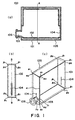
- Figure 1 is a schematic view of a liquid container according to an embodiment of the present invention, wherein (a) is a sectional view, (b) is a side view, (c) is a perspective view.
- Figure 2 is an illustration of a liquid container according to first embodiment of the present invention, wherein (a), (b) are sectional views, (c) is a perspective view, and (d) shows a pinch-off portion.
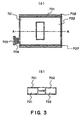
- Figure 3 is an illustration of an operation of a liquid container according to a second embodiment of the present invention, wherein (a) shows the maximum area side, and (b) is a sectional view taken along a line A-A'.
- Figure 4 is an illustration of a liquid container according to a third embodiment.
- Figure 5 is a sectional view showing a structure of a liquid container according to an embodiment of the present invention, wherein (a)-(b) and (c)-(d) are sectional views taken along a plane perpendicular to a maximum area side and A-A sectional views in a liquid container according to a fourth embodiment and a modified example thereof.
- Figure 6 is a sectional view showing a structure of a liquid container according to an embodiment of the present invention, wherein (a)-(b) and (c)-(d) are sectional views taken along a plane perpendicular to a maximum area side and A-A sectional views in a liquid container according to a fifth embodiment and a modified example thereof.
- Figure 7 is a sectional view showing a structure of a liquid container according to an embodiment of the present invention, wherein (a)-(b) and (c)-(d) are sectional views taken along a plane perpendicular to a maximum area side and A-A sectional views in a liquid container according to a sixth embodiment and a modified example thereof.
- Figure 8 is a sectional view showing a structure of a liquid container according to an embodiment of the present invention, wherein (a)-(b) and (c)-(d) are sectional views taken along a plane perpendicular to a maximum area side and A-A sectional views in a liquid container according to a seventh embodiment and a modified example thereof.
- Figure 9 is illustration of a liquid container according to an embodiment of the present invention, wherein (a)-(c) and (d)-(f) are a top plan view, a top plan view and a side view of a liquid container according to an eighth embodiment of the present invention, and, (g) is a sectional view illustrating a configuration of a projection formed in the liquid container.
- Figure 10 illustrates a liquid container according to a ninth embodiment of the present invention, wherein (a)-(c) and (d)-(f) are top plan views, top plan views and side views of the container according to this embodiment and modification thereof.
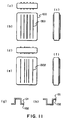
- Figure 11 ((a)-(c) and (d)-(f)) is a top plan view, a top plan view and a side view of a device according to tenth embodiment and a modified example, and, (g), (h) are sectional views of a projection formed on a liquid container.
- Figure 12 is an illustration of a liquid container according to an eleventh embodiment of the present invention, wherein (a)-(c) and (d)-(f) are top plan views, top plan views and side views of the liquid container of this embodiment and the modification thereof.
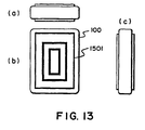
- Figure 13 is a top plan view, a top plan view and a side view of a device according to an eleventh embodiment of present invention and a modified example thereof.
- Figure 14 ((a)-(c) and (d)-(f)) is a top plan view, a top plan view and a side view of a device according to twelfth embodiment and a modified example, and, (g), (h) are sectional views of a projection formed on a liquid container.
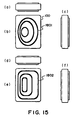
- Figure 15 ((a)-(c) and (d)-(f)) is a top plan view, top plan view and a side view of a device according to a thirteenth embodiment of the present invention a modification thereof.
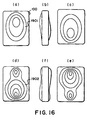
- Figure 16 ((a)-(c) and (d)-(f)) is a top plan view, a top plan view and a rear surface Figure of a fourteenth embodiment of the present invention and a modification thereof.
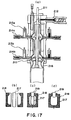
- Figure 17 shows a manufacturing step of an ink container of the present invention.
- Figure 18 is an illustration of a parison including intermittent reinforcing members, wherein (a) is a sectional view taken along a plane perpendicular to a supply direction of the parison, and (b) is a sectional view taken along a line A-A in (a), showing a nipping portion of the parison and a metal mold.
- Figure 19 is a schematic view showing a state of a liquid container in a manufacturing step of a liquid container according to an embodiment of the present invention.
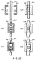
- Figure 20 is a schematic view showing a state of a liquid container in a manufacturing step of a liquid container according to an embodiment of the present invention.
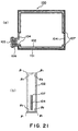
- Figure 21 is a schematic illustration of a liquid container according to a further embodiment of the present invention, wherein (a) is a sectional view, and (b) is a side view.
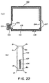
- Figure 22 is a schematic illustration of a liquid container according to a further embodiment of the present invention, wherein (a) is a sectional view, and (b) is a side view.
- Figure 23 is a schematic illustration of a liquid container according to a further embodiment of the present invention, wherein (a) is a sectional view, and (b) is a side view.
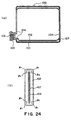
- Figure 24 is a schematic illustration of a liquid container according to a further embodiment of the present invention, wherein (a) is a sectional view, and (b) is a side view.
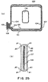
- Figure 25 is a schematic illustration of a liquid container according to a further embodiment of the present invention, wherein (a) is a sectional view, and (b) is a side view.
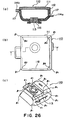
- Figure 26 is a schematic illustration of a liquid container according to a further embodiment of the present invention, wherein (a) is a sectional view, (b) is a plan view, and (c) is a perspective view where bottom is at the top.
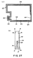
- Figure 27 is a schematic illustration of a liquid container according to a further embodiment of the present invention, wherein (a) is a sectional view, and (b) is a side view.
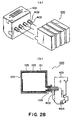
- Figure 28 (a) is a perspective view of a liquid container and a recording head connectable thereto, (b) is a sectional view showing the liquid container and the recording head connected to each other.
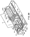
- Figure 29 is a schematic illustration of an ink jet recording apparatus using a liquid container according to an embodiment of the present invention.
- Figure 1 shows a structure of an ink container according to an embodiment of the present invention, wherein (a) is a sectional view, (b) is a side view, and (c) is a perspective view.
- the ink container of this embodiment is manufactured through a direct blow molding, with which an inner wall and an outer wall of the ink container are simultaneously molded through one step.
- the ink container 100 shown in Figure 1 (a) comprises an outer wall 101 and an inner wall 102.
- the ink is contained in an ink accommodating portion which is defined by inner wall 102, and the inner wall deforms with discharging of the ink therefrom.
- the outer wall 101 functions to protect the ink accommodating portion to prevent the leakage of the ink to the outside upon the unintentional deformation of the inner wall containing the ink.
- Designated by 103 is an ink supplying portion for supplying the ink out of the inside of the container, and functions as connecting portion with an ink introduction portion of an unshown ink jet head.
- the corner means a crossing portion of at least 3 surfaces of polyhedron constituting the liquid container, and a portion corresponding to a crossing portion of extended surfaces thereof, and it is a bent portion from the beginning of molding.
- the reference characters designating the corners are such that ⁇ means corners formed by the surfaces having the ink supply port, and ⁇ means the other corners; and suffix 1 is for the outer wall, and suffix 2 is for the inner wall.
- the crossing portions between the substantial flat surface and the curved surface of the cylindrical ink supplying portion is designated by ⁇ ; and the outer wall and inner wall are formed at the crossing portions, too, which are designated by ⁇ 1 and ⁇ 2.
- the ink container 100 is constituted by eight flat surfaces, and a cylindrical ink supplying portion 103 having curved surface is added.
- the maximum area sides of the inner and outer wall at the opposite sides of the ink supplying portion 103, among the 8 surfaces, are separated by six corner portions ( ⁇ 1, ⁇ 1, ⁇ 1, ⁇ 1, ⁇ 1, ⁇ 1), ( ⁇ 2, ⁇ 2, ⁇ 2, ⁇ 2, ⁇ 2, ⁇ 2), which will be described hereinafter.
- the thickness distribution of the inner wall having the maximum area is such that thickness at the corner portion is thinner than that of the central portion, and the thickness gradually decreases toward the corner portion, so that it is convex toward the ink accommodating portion.
- the direction is the same as the direction of deformation of the surface, and it promotes the deformation, as will be described hereinafter.
- the corner of the inner wall is provided by 3 surfaces, which will be described hereinafter, so that strength of the corner as a whole is relatively high as compared with the strength of the central portion of the surfaces.
- the surfaces at and adjacent each corner has a thickness smaller than the center portions of the surfaces providing the corner, thus permitting easy movement of the surfaces, as will be described hereinafter. It is desirable that portions constituting the inner wall corner have substantially the same thicknesses.
- the crossing portions ⁇ 1, ⁇ 2 where cylindrical surface and a flat surface are crossed is not easily deformed by the discharge of the ink due to normal printing operation of the ink jet recording means because the ink supplying portion is cylindrical.
- the configuration of the ink supplying portion is not limited to the cylindrical, though. It may be prism configuration, and even in such a case, the ink supplying portion of the sufficiently smaller than the ink accommodating portion, so that crossing portion is still not easily deformed by the ink discharging. Therefore, even when the ink is completely consumed, the inner wall and the outer wall are not deformed at the ink supplying portion and maintain the initial state.
- Designated by 104 is a welded portion for forming a sealed space by the inner wall 102.
- the welded portion is provided by pinching a parison of an ink container by metal molds during blow molding which will be described hereinafter, and the inner wall 102 is welded and is closely contacted to the outer wall 101, and therefore, supports the inner wall 102 (functioning as a supporting portion).
- the fused portion 104 in this embodiment looks linear, but the simple linear configuration is not mandatory; the configuration of the fused portion is optional as long as the ink container can be easily extracted from the die. Further, its length does not necessarily have to be limited to the length given in this embodiment; it is optional as long as the fused portion does not extend beyond the lateral walls.
- a reference numeral 105 designates an air vent through which air is introduced between the inner shell 102 and the outer shell 101 when the volume of the inner shell 102 decreases in response to the consumption of the ink contained therein. It may be a simple opening or may be constituted of an air flow valve. In Figure 1, this air vent is a simple opening (hole).
- Designated by 106 is an ink discharge permission member provided with an ink leakage preventing function for preventing leakage of the ink from the ink supplying portion when a small scale vibration or external pressure is imparted to the container. It functions as a connecting portion relative to the ink jet head. It uses a unidirectional fibrous material of an ink absorbing material and has a meniscus retaining portion. It virtually seals the ink holding portion, and when the ink tapping member of the ink jet head is inserted into the ink supply port, it enables the ink within the ink holding portion to be fed out while maintaining the airtight condition.
- a rubber plug or valve is usable in place of a press-contact member at the ink discharge permission member 106.
- Figure 2 is an illustration of a liquid container according to first embodiment of the present invention, wherein (a), (b) are sectional views, (c) is a perspective view, and (d) shows a pinch-off portion. And, (a) is a sectional view taken along a line B-B' in (b), and (b) is a sectional view taken along an A-A' of (a).
- the structure is fundamentally the same as with Figure 1, and it comprises an outer wall (casing) 701, an inner wall 702, a liquid supply portion 703, a pinch-off portion, a liquid discharge permission member 706.
- the central portion of a maximum area side of the liquid container is provided with a through-hole 710, by which means the inner wall 702 and the outer wall 701 are substantially annular.
- the liquid supply portion 703 side of the outer periphery of the outer wall 701, the opposite side and the circumference of the through-hole 710, are pinch-off portions, so that liquid containing portion is separated into a first accommodating portion 721 closer to the ]liquid supply portion 703 and a second accommodating portion 722 at the opposite side with the through-hole 710 therebetween.
- the corner portions of the inner wall correspond to the corner portions of the outer wall in the initial state, so that inner wall of the liquid container has a configuration similar to the outer wall 701 of the liquid container, by which the inner wall 702 of the liquid container extends along the outer wall 701 of the liquid container with a space of a predetermined range.
- the dead space existing when a bladder-like container is contained in a conventional casing can be removed, so that liquid containing amount per unit volume of the outer wall of the liquid container can be increased (liquid containing efficiency can be increased).
- the inner walls 702 are pressed and pinched by the outer walls 701, the inner wall 702 and the outer wall 701 are separable due to their materials, so that inner wall 702 and the outer wall 701 can be separated at the pinch-off portion, too, and therefore, a gap 707 is formed between the outer wall 701 and the inner wall 702.
- the gap 707 functions as an air vent path (air vent) to permit introduction of the air to between the inner wall 702 and the outer wall 701 when the volume of the inner wall 702 reduces as a result of consumption of the inside ink.
- the air vent may be provided in any different manner, without using the gap 707 at the pinch-off portion, and it may be provided by forming an opening in the outer wall, for example, as shown in Figure 1.
- the pinch-off portion is provided along the entire width of the lateral side of the container, so that inner wall is stably supported, thus providing stabilized negative pressure with the discharged liquid.
- the pinch-off portions are provided widely at positions opposed to each other, by which the mechanical strength of the container per se is enhanced, and therefore, the container is reliable against external shock or the like.
- the pinch-off portion may be separated from the outer wall 701, but even if it occurs, the direction of the deformation is limited because the pinch-off portion has a certain length. Accordingly, even when the pinch-off portion is separated from the outer wall, the deformation is not irregular, but proper balance is maintained.
- the inner wall of the first accommodating portion 721 tends to deform at such a position as is most easily deformed under the condition of the restriction against the deformation described hereinbefore.
- the deformation starts at substantially the central portion of at least one of the surfaces of the inner wall corresponding to the maximum area sides of the outer walls of the first accommodating portion 721 among the substantially flat surfaces thereof.
- the surface Since the surface is substantially flat, it continuously deforms toward the surface opposite therefrom in accordance with the reduction amount of the liquid in the first accommodating portion 721. Therefore, the stabilization of the negative pressure time the liquid supply can be accomplished, and simultaneously, the ambience is introduced into between the inner wall 702 and the outer wall 701.
- the liquid in the second accommodating portion 722 is supplied into the first accommodating portion 721, so that liquid in the second accommodating portion 722 is supplied to the outside through the first accommodating portion and the liquid supply portion 703, by which the second accommodating portion 722 collapses similarly to the first accommodating portion 721.
- the corner portions of the inner walls of the first accommodating portion 721 and the second accommodating portion 722 are removed or separated from the corresponding corner portions of the outer wall.
- the thickness of the inner wall 702 having the maximum area is thicker in the center portion than the marginal portion by the manufacturing, but the strength is larger at the corner portion since three surfaces are crossed.
- second accommodating portion 722 makes constant the degree of contraction of the first accommodating portion 721 relative to the liquid discharge amount.
- the size of the through-hole 710 is not limited, but it is preferable to be 20 % of the area of the maximum area side.
- the provision of the through-hole in the liquid container enhances the mechanical strength, and permits stabilized supply of the liquid from the inside.
- the circumference of the through-hole is a pinch-off portion, and the ambience is introduced there between the inner wall and the outer wall to further stabilize the liquid supply.
- the provision of the through-hole is effective to reinforce the maximum area side when the liquid containing portion contains the liquid to its maximum, and therefore, the outer surface of the inner wall and the inner surface of the outer wall are contacted to each other; and when the liquid is consumed, the provision of the through-hole is effective to maintain the position of the liquid containing portion against the external shock, since the inner wall is supported by the outer wall around the through-hole.
- the through-hole is provided at the center portion of the maximum area side of the liquid container.
- the inner wall portions opposed to each other at the through-hole position are stuck to each other, as if they are sandwiched by the outer walls to form a concave.
- Figure 3 is an illustration of an operation of a liquid container according to a second embodiment of the present invention, wherein (a) shows the maximum area side, and (b) is a sectional view taken along a line A-A'.
- the behavior in this embodiment is substantially the same as in the foregoing if the stuck portion is located at the position where the pinch-off portion of the through-hole is disposed in the first embodiment.
- the inner wall 702 is fixed at the stuck portion at the center portion of the liquid container, and therefore, the inner wall 702 is more stabilized when an external shock is imparted.
- the stuck portion is at substantially the middle of the opposed surfaces having the maximum areas, but the present invention is not limited if it is parallel with the surface having the maximum area.
- An inner wall portion may be stuck to the other side.
- Figure 4 is an illustration of a liquid container according to a third embodiment.
- two through-holes 701 are provided.
- the positions where the through-holes 701 are provided, are determined such that first accommodating portion 721, a second accommodating portion 722 and a third accommodating portion 723 into which the liquid containing portion are separated by the through-holes 701 have the length 11, 12 and 13, wherein 11 > 12 > 13 is satisfied.
- the liquid in the first accommodating portion 721 is first consumed, and then the liquid in the second accommodating portion 722 is consumed, and then the liquid in the third accommodating portion 723 is consumed.
- the number of the through-holes is two, but the number is not limited if the order of the consumptions of the liquid can be controlled.
- the effects of the first to third embodiments are as follows.
- Figure 5 is a sectional view showing a structure of a liquid container according to an embodiment of the present invention, wherein (a)-(b) and (c)-(d) are sectional views taken along a plane perpendicular to a maximum area side and A-A sectional views in a liquid container according to a fourth embodiment and a modified example thereof.
- the container comprises an outer wall (casing) 101, an inner wall 102, a liquid discharge portion 103, a pinch-off portion (unshown), an air introducing portion (unshown), and a liquid discharge permission member 106.
- a reinforcing member 109 is provided between the inner wall and the outer wall at the maximum area side of the inner wall 102 of the liquid container 100.
- the reinforcing member 109 is extended from the central portion of the maximum area side toward the neighborhood of the marginal portion, but it does not exists in the neighborhood of the marginal portion.
- the reinforcing member has a thickness which is large at the central portion, and decreases toward the marginal portion.
- the material of the container will be described hereinafter, but they are of materials which show good welding property (between the reinforcing member and the inner wall) so that reinforcing member is not separable from the inner wall.
- the combination of the inner wall and the reinforcing member are called inner shell.
- the thickness of the inner shell is smaller in the marginal portion than in the center portion.
- the reinforcing member is provided at the maximum area side for the following reasons.
- the inner wall tends to deform at a portion which is most easily deformed under the restricted condition.
- the marginal portions of the inner shell corresponding to the maximum area side of the flat outer wall surfaces do not have a corner portion or a reinforcing member, and the strength is low there so that these portions tend to deform inwardly.
- the outer wall suppresses the displacement of the corner portion of the inner wall.
- the position of the corner portions ⁇ 2, ⁇ 2 of the this liquid container hardly deforms, so that liquid containing portion receives the force toward the deformation due to the consumption of the ink and the force returning to the initial state, by which the negative pressure is stabilized.
- the portions of the maximum area sides which have the reinforcing member portions deform toward each other while maintaining the parallelism therebetween.
- the portion having the reinforcing member is substantially flat, so that it continuously and uniformly deforms toward the opposite surface in accordance with the reduction of the ink in the ink accommodating portion. Accordingly, there is no continuous large-scale deformation of the ink accommodating portion during ejection and non-ejection periods, so that negative pressure is stably formed and maintained.
- the reinforcing member is to reinforce the maximum surface of the inner shell, it has a higher strength than the inner wall. Unlike the case where the thickness of the entirety of the inner wall is large, the strength is enhanced only at the zone except for the marginal portion, by which the local strength of the maximum area side can be adjusted.
- a bladder-like container having a rectangular parallelopiped configuration as shown in Figure 1 tends to deform first at the central portion of the maximum area side or side with the discharge of the liquid.
- the thickness of the reinforcing member is larger at the central portion and is small at the marginal portion, so that resistance against the deformation is strong at the central portion, and decreases toward the marginal portion.
- the marginal portion is deformed assuredly, and the subsequent deformation responsive to the consumption of the liquid is promoted.
- the thickness of the reinforcing member is different if the material of the reinforcing member and/or the desired strength is different, and it may be small if the strength of the material is large, but it is desirably not more than 10 % of the thickness of the liquid container namely the movement distance of the maximum area side.
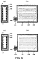
- Figure 6 is a sectional view showing a structure of a liquid container according to an embodiment of the present invention, wherein (a)-(b) and (c)-(d) are sectional views taken along a plane perpendicular to a maximum area side and A-A sectional views in a liquid container according to a fifth embodiment and a modified example thereof.
- a plurality of the reinforcing members 109 of the fourth embodiment which are parallel with the longitudinal direction of the maximum area of the inner shell, are provided.
- Figure 6, (a) and (b) shows an example having a reinforcing member between the inner wall and the outer wall
- Figure 6 (c) and (d) shows a modified example having a reinforcing member at the liquid containing portion side of the inner wall.
- the inner shell has an outer surface contacted to the inner surface of the casing without space therebetween due to the manufacturing method which will be described hereinafter, and therefore, when the reinforcing member is provided between the inner wall and the outer wall, the inner wall extends around the reinforcing member, as shown in Figure 6, (a). For this reason, when it is necessary that reinforcing member has a larger thickness, it is desirable to provide the reinforcing member on the liquid containing portion side of the inner wall as in the modified example shown in Figure 6, (c) and (d).
- Figure 7 is a sectional view showing a structure of a liquid container according to an embodiment of the present invention, wherein (a)-(b) and (c)-(d) are sectional views taken along a plane perpendicular to a maximum area side and A-A sectional views in a liquid container according to a fifth embodiment and a modified example thereof.
- a plurality of the reinforcing members 109 are extended in the longitudinal direction of the maximum area side (fifth embodiment of Figure 6), have a width h which is large in the middle portion and is small in the marginal portion.
- Figure 7, (a) and (b) shows an example having a reinforcing member between the inner wall and the outer wall
- Figure 7, (c) and (d) shows a modified example having a reinforcing member at the liquid containing portion side of the inner wall.
- the reinforcing member is desirably provided on the liquid containing portion side of the inner wall.
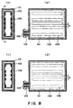
- Figure 8 is a sectional view showing a structure of a liquid container according to an embodiment of the present invention, wherein (a)-(b) and (c)-(d) are sectional views taken along a plane perpendicular to a maximum area side and A-A sectional views in a liquid container according to a fifth embodiment and a modified example thereof.
- the following embodiments have the same fundamental structure as in the first embodiment shown in Figure 1, and it comprises an outer wall (casing) 101, an inner wall 102, a liquid discharge portion 103, a pinch-off portion (unshown), an air vent (unshown), and a liquid discharge permission member 106.
- a plurality of the reinforcing members 109 parallel with the longitudinal direction of the maximum areas side of fifth embodiment ( Figure 6) is modified to have a clearance b which is small in the middle portion and large in the reinforcing member 109.
- the local strength can be more easily adjusted.
- the effects of the fourth - seventh embodiment will are as follows.
- the provision of the reinforcing member permits the local adjustment of the strength against the collapse of the inner shell, so that negative pressure can be stabilized for a long term, and the ink can be stably supplied for a long term.
- the local adjustment thus permitted, allows the regulation of the collapse of the inner wall in accordance with the intended purpose.
- FIG 9 is illustration of a liquid container according to an embodiment of the present invention, wherein (a)-(c) and (d)-(f) are a top plan view, a top plan view and a side view of a liquid container according to an eighth embodiment of the present invention, and, (g) is a sectional view illustrating a configuration of a projection formed in the liquid container.
- the fundamental structure of this embodiment is the same as that of Figure 1 embodiment. However, in the present embodiment, a projection is provided. In Figure 9, the supply port is not shown for the better illustration of this feature.
- the use is made with a projection in place of the reinforcing member used in the fourth to seventh embodiment, by which the local strength against the collapse of the maximum area side, can be adjusted, thus providing the similar advantages as the reinforcing member.
- the member capable of adjusting a local strength against the deformation of the maximum area side is called deformation confinement member, including reinforcing member and the rib.
- the maximum area side of the liquid container 100 is provided with ribs 1201, 1202, and the opposing surface (unshown) of the surface shown in Figure 9, (b) and Figure 9, (e) is provided with the similar rib.
- the configuration of the projection (rib), as shown in the sectional view of Figure 9, (g), is such that inner surface of the outer wall 101 and the outer surface of the inner wall 102 are equivalent or corresponding to each other, it is trapezoidal configuration projecting toward the outer wall 101 from the inner wall 102.
- the configuration is not limited, and may be rectangular (rectangular), or may project from the outer wall 101 toward the inner wall 102.
- the ribs 1201, 1202 are extended to the neighborhood of the marginal portion of the maximum side, and it is curved to form a small curved surface configuration at the marginal portion.
- the ribs 1201 in the embodiment and the ribs 1202 in the modified example are in the form of a lattice.
- the ribs 1201 are uniformly distributed in the longitudinal direction (vertical on the Figure) and in the horizontal direction, and projections having different widths are combined.
- the width is larger in the central portion, and in the modified example, the intervals are smaller in the central portion, and are larger at the marginal portion.
- the strength or the resistance against the deformation is larger in the central portion and is smaller in the marginal portion.
- the larger width of the rib does not directly means the larger strength. But, when the liquid container 100 is manufactured through the blow molding, the resin material easily goes around, and the inner wall configuration and the outer wall configuration correspond to each other as shown in Figure 9, (g), and therefore, the strength against the deformation increases as a result.
- the thickness of the inner wall 102 was 0.5 mm; the thickness of the outer wall 101 was 1.0 mm; and the height of the rib was approx. 1.2 mm.
- the practical width of the rib in this case was 1.5 mm - 2.0 mm. When the width is smaller, the resin material goes less easily around, and therefore, the molding becomes difficult. From this standpoint, it is desirable to form an elongated projection having a larger width than that.
- the ration thereof to the thickness of the liquid container is desirably approx. 5 - 30 %.
- Figure 10 illustrates a liquid container according to a ninth embodiment of the present invention, wherein (a)-(c) and (d)-(f) are top plan views, top plan views and side views of the container according to this embodiment and modification thereof.
- This embodiment is a modification of the eighth embodiment shown in Figure 9 as a deformation confinement member, wherein thicknesses of the ribs 1201, 1202 are modified to be larger in the central portion of the maximum area side, and are decreased gradually toward the marginal portion, and these modified ribs are shown as ribs 1203, 1204. With this configuration, the resistance against the collapse can be enhanced in the central portion of the maximum area side.
- the thickness linearly changes, and in the modified example it gradually non-linearly changes. Either is usable.
- Figure 11 ((a)-(c) and (d)-(f)) is a top plan view, a top plan view and a side view of a device according to tenth embodiment and a modified example, and, (g), (h) are sectional views of a projection formed on a liquid container.
- ribs 1301, 1302 are formed on the maximum area side of the liquid container 100.
- Each rib 1301, 1302 is in the form of an elongated projection extending in the vertical direction ( Figure) of the maximum area side.
- the similar ribs are formed on the side (unshown) opposite from the side shown in the Figure.
- the ribs 1301 in this embodiment are uniformly distributed from the center of the maximum area side, and the widths reduce away from the center so that strength or resistance against the collapse is high in the center portion of the maximum area side.
- the ribs 1302 formed in the modified example of this embodiment have the same widths, but they are arranged at higher density in the center portion of the maximum area side then the marginal portion so that resistance against the collapse is higher in the central portion of the maximum area side.
- the ribs are extended only in the vertical direction to provide uniform vertical collapse, thus regulating the deformation of the liquid container 100.
- the widths and/or the arrangement of the ribs may be determined such that resistance against the collapse is high adjacent to the supply port, by which the deformation is forced to start at a position away from the supply port, so that ink accommodated therein can be efficiently consumed.
- the configurations of the elongated projections may be as shown in Figure 9, (g) (trapezoidal configuration), and may be the ones shown in Figure 11, (g), Figure 11, (h) (rectangular). It may project from the inner wall 102 toward the outer wall 101 or may be a combination with projections from the outer wall 101 toward the inner wall 102. By employing the projection projecting from the outer wall 101 toward the inner wall 102, the deformation can be started at an earlier stage. Such projections may be provided at positions distant from the supply port to permit the deformation to increase the ink consumption efficiency.
- Figure 12 is an illustration of a liquid container according to an eleventh embodiment of the present invention, wherein (a)-(c) and (d)-(f) are top plan views, top plan views and side views of the liquid container of this embodiment and the modification thereof.
- concentric elliptical ribs 1401 having different diameters, are formed on the maximum area side of the liquid container 100.
- ribs 1402 are substantially concentric rectangular which are rounded at the corner portions.
- ribs 1501 are substantially concentric rectangular having different sizes.
- the similar ribs are formed on the opposite sides (unshown).
- Ribs 1401, 1402, 1501 constituting the projections are arranged concentrically about the center of the maximum area side, thus increasing the strength against the deformation at the center portion thereof. Therefore, the deformation substantially occurs from the marginal portion toward the central portion.
- the intervals of the ribs may become smaller toward the center portion of the maximum area side as in the foregoing embodiment.
- Figure 14 ((a)-(c) and (d)-(f)) is a top plan view, a top plan view and a side view of a device according to twelfth embodiment and a modified example.
- the maximum area side of the liquid container 100 is provided with ribs 1601, 1602.
- Each rib 1601, 1602 is in the form of an elongated projection extending in the vertical direction ( Figure) of the maximum area side.
- the similar ribs are formed on the side (unshown) opposite from the side shown in the Figure.
- the ribs 1601 of this embodiment is in the form of columnar projections having different sizes, wherein the sizes of the projections gradually decreases away from the center of the maximum area side.
- the ribs 1602 are column-like projections, wherein the sizes of the projections gradually decreases away from the center of the maximum area side.
- the strength against the collapse is higher in the center portion of the maximum area side.
- the strength, against the collapse, along the line connecting the outer periphery portion is uniform, so that collapsing way can be controlled.
- the deformation occurs along the broken line shown in Figure 14, (b), so that deformation occurs similarly to eleventh embodiment.
- the deformation occurs along the broken line in Figure 14, (e).
- the configuration of the projection may be trapezoidal as shown in Figure 14, (g), but may be semi-spherical as shown in Figure 14, (i).
- the configuration of the column-like projection in the modified examples shown in Figure 14, (d)-(f), is as shown in Figure 14, (h).
- Figure 15 ((a)-(c) and (d)-(f)) is a top plan view, a top plan view and a side view of a device according to thirteenth embodiment and a modified example, and, (g), (h) are sectional views of a projection formed on a liquid container.
- the elliptical projections having different diameters or the rounded rectangular projections having different sizes are not concentric, but are offset (ribs 1801, 1802).
- the similar ribs are formed on the opposite side (unshown), but the ribs on the opposite side are offset toward right as seen from the outside, so that they are overlapped with the ribs 1801, 1802, as seen radioscopically.
- the plurality of projections are deviated toward the left in the drawing so that strength in the left side is higher than in the right side. In such a case, the deformation starts in the right side and progresses toward the left.
- the projections may be arranged such that strength against the collapse is higher adjacent the supply port, by which the deformation starts at positions remote from the supply port, thus accomplishing the efficient use of the ink.
- Figure 16 ((a)-(c) and (d)-(f)) is a top plan view, a top plan view and a rear surface Figure of a fourteenth embodiment of the present invention and a modification thereof.
- projections 1901, 1902 having different configurations on the opposite maximum area sides.
- the projection 1901 formed in the fourteenth embodiment has a single apex, and in the modified example, the projection 1902 has two apexes.
- the curves in Figure 16, (a), (c), (d) and (e) does not show the actual configuration, but is contour lines of the maximum area sides.
- the projections (deformation confinement member) are disposed at the same positions when the maximum area sides are seen radioscopically, but in this embodiment, the apexes of the projection 1901 and the projection 1902 are deviated from each other and from the center of the maximum area side when the maximum area side is seen radioscopically, and the lowest height positions of the projections are different. By this, the ink flow path is assuredly formed even when the maximum area sides are contacted to each other.
- the strength again the collapse of the inner wall can be locally adjusted, so that negative pressure can be stabilized for a long term.
- the local adjustment thus permitted, allows the regulation of the collapse of the inner wall in accordance with the intended purpose.
- the strength of the outer wall is enhanced by the formation of the rib, and therefore, the thickness of the outer wall can be reduced, thus permitting reduction of the manufacturing cost.
- the resultant reduction of the weight makes design of the carriage easier, and permits low mechanical strength material can be used, thus further permitting easy design.
- the shock resistance is assured without increasing the dead space in the container, and the ink supply with negative pressure can be accomplished, even when the size of the container is large.
- the size of the container to which the embodiments are usable is about 10 - 1000 cm 3 although it is dependent upon the thickness and the strength or the like of the inner wall.
- the static head difference can be additionally used to stabilize the supply of the liquid. In such a case, the disposition space required can be made smaller than when only the static head difference is used.
- the upper limit of the size of the container to which the present invention is usable is larger than the above-described upper limit 1000 cm 3 .
- the ink container of the present invention has a double wall structure of molding resin material, and the outer wall (casing) is thick to provide enough strength, and on the other hand, the inner wall is of soft material and is thin to permit to follow the variation of the volume of the ink.
- the inner wall is provided with non-separable reinforcing members.
- the material of the inner wall is desirably the one having an anti-ink property, and that of the outer wall desirably has a shock resistance, and the material of the reinforcing member used in fourth to seventh embodiments desirably has a strength.
- the reinforcing member when the reinforcing member is provided between the outer wall and the inner wall, it desirably does not have the welding property relative to the outer wall, and when the reinforcing member is provided on the inside of the inner wall, the material thereof desirably exhibits good contact property relative to the liquid.
- a method using blow molding is employed so that structural walls of the ink container can be formed without drawing the resin materials.
- structural walls of the ink container can be formed without drawing the resin materials. Therefore, the inner wall of the ink container, which constitutes the ink holding portion, is enabled to substantially omnidirectionally withstand the load. As a result, no matter which direction the ink remaining in the inner wall shifts after the ink contained in the inner wall is consumed by a certain amount, the inner wall can reliably retain the ink, thus further improving the overall durability of the ink container.
- blow molding As for the choice of blow molding, injection blow molding, direct blow molding, double wall blow molding, and the like are available.
- Figure 17 shows a manufacturing step of an ink container of the present invention.
- Figure 18 is an illustration of a parison including intermittent reinforcing members, wherein (a) is a sectional view taken along a plane perpendicular to a supply direction of the parison, and (b) is a sectional view taken along a line A-A in (a), showing a nipping portion of the parison and a metal mold.
- 211 is a main accumulator for supplying inner wall resin material
- 212 is a main extruder for extruding the inner wall resin material
- 213a is a sub-accumulator for supplying the assistance member resin material
- 214a is a sub-extruder for extruding the assistance member resin material
- 213b is a sub-accumulator for supplying the outer wall resin material
- 214b is a sub-extruder for extruding the outer wall resin material.
- a multi-layer nozzle is used as an injection nozzle, and resin material (outside resin material) 217a for forming a casing and resin material for forming an inner shell (inside resin material) 217b and 217c, are simultaneously ejected to manufacture a substantially cylindrical parison 217 comprising integral first and second parisons.
- the layer 217a for forming the casing and the layer 217c for forming the inner wall are supplied continuously in both of the direction of the supply and the direction perpendicular thereto, but the layer 217b for forming the reinforcing member are supplied intermittently in both of the direction of the supply and the direction perpendicular thereto.
- Figure 18 shows a parison for manufacturing the liquid container of the fourth embodiment.
- the separation layer 217b is arranged inside the separation layer 217b for the inner wall.
- the sub-accumulator 213a of the manufacturing apparatus and the sub-extruder 214a thereof are used for the inner wall, and the sub-accumulator 211 and the sub-extruder 212 are used for the assistance member.
- the extruding manner of the extruder is such that layer 217c for the inner wall is continuous in both of the direction of supply and the direction perpendicular thereto, and the layer 217b for the reinforcing member is intermittent in both of the supply direction and perpendicular thereto.
- the reinforcing member is separated in the section shown in Figure 18, (a). In such a case, the extruding manner of the extruder is changed properly.
- the resin material for the reinforcing member is supplied in parallel with the direction of the supply of the parison, and therefore, when a plurality of reinforcing members are to be provided on the maximum area side, the longitudinal direction of the maximum area side is made the same as the parison supply direction and as the direction of the reinforcing member from the standpoint of the easy division of the mold.
- the plurality of the reinforcing members are extended in parallel with the longitudinal direction in view of the above, but it is possible to provide the rib perpendicular to the longitudinal direction of the parison supply direction if the parison supply direction and the longitudinal direction of the maximum area side are made orthogonal to each other.
- the inside resin material and the outside resin material may be contacted, and they may be out of contact, or they may be partly contacted.
- the surfaces where they are contacted are of the materials which are non-contactable to each other, or a chemical compound is added to one of the materials to make them separable.
- the inside material or the outside material is given a multi-layer structure so that contact surfaces are made of different kind materials.
- the parison 217 After the parison 217 is prepared, it is pinched by moving the metal mold 218 from the position shown in Figure 17, (b) to the position shown in Figure 17, (c). Then, the air is injected through an air nozzle 219 as shown in Figure 17, (c) to effect blow molding into a configuration of the metal mold 218. At this time, the inner shell and the casing are closely contacted without a space therebetween. It is preferable to control the temperature of the mold during the molding within the range of plus and minus 30 o C from a reference temperature, since then the variation in the thickness of each wall of the ink container can be decreased.
- Figure 19 is a schematic view showing a state of a liquid container in a manufacturing step of a liquid container according to an embodiment of the present invention, and is a side view of the mold shown in Figure 17, (b)-(d).
- Figure 19 (a1), (b1), (c1) is a view as seen in the mold-dividing direction, and (a2), (b2), (c2) are views as seen the orthogonal direction.
- the container is separated from the mold, and the portion of the inner shell other than the ink supplying portion, is separated from the outer wall.
- vacuum is usable, and in another method, the molding resin materials of the inner wall and the outer wall are of materials having different thermal expansion coefficients (shrinkage rates).
- the separation is automatically effected so that number of steps in the manufacturing is reduced.
- the inner shell and the outer wall may be separated by applying external force after molding at a position where the parison has been pinched during the molding, by which a space in fluid communication with the ambient air, is provided therebetween and may be used as air vent. This is preferable since then the number of manufacturing steps can be reduced.
- the ink is injected.
- the ink accommodating portion may be expanded by compressed air to provide the same shape as in the initial stage of the container, and then the ink injection may be carried out.
- the ink may be injected by pressurization.
- the inner shell and the casing of the ink container is separable by discharge of the ink.
- a cap having the liquid discharge permission member 106 is mounted.
- the parison 217 is processed while it still has a viscosity, and therefore, the inner wall resin material, outer wall resin material and the reinforcing member resin material do not acquire orientation property.
- blow molding can reduce the number of manufacturing steps and the number of the components, which in turn can improve yield, and also allows the inner wall to be formed in such a manner that edges and corners of the inner wall are set in those of the outer wall in an orderly manner.
- the outer wall and the inner wall become similar in external configuration; therefore, the inner wall snugly fits within the outer shell, holding a predetermined gap between them.
- a large dead space found in the conventional ink container comprising an outer shell and an ink containing pouch enclosed therein can be eliminated, increasing the amount of the ink retainable per unit volume of the outer shell (ink holding efficiency can be improved).
- the separable casing and the inner shell have the similar structure since they are provided by uniformly expanding a cylindrical parison into a prism by air blow through the direct blow manufacturing method. More particularly, in the inner shell, the thickness of the wall of the container is thinner adjacent the corner portions than at the center portions. Similarly, the thickness of the casing is thinner adjacent the corner portions than at the center portions.
- the inner shell is laminated to an outer wall having a thickness distribution of gradually decreasing thickness from the central portion toward the corner portions.
- the inner shell has an outer surface complementary with the inner surface of the outer wall.
- the outer surface of the inner shell follows despite the thickness distribution of the outer wall, and therefore, it is convex toward the liquid containing portion side formed by the inner walls.
- the reinforcing member is formed by lamination between the outer wall and the inner wall or the ink accommodating portion side of the inner wall, so that in any case, the thickness distribution is, similarly to the outer wall, that thickness is large in the central portion and gradually decreases toward the marginal portion and that it is convex toward the liquid containing portion side of the inner wall. Therefore, the adjustment of the local strength can be easily accomplished without particular control relating to the thickness when the parison of the reinforcing member is supplied.
- Figure 20 shows an example of a relation between the metal mold and the parison in the case of the second embodiment.
- Figure 20 shows a view of the mold used for the molding, as seen in the lateral direction, wherein (a1), (b1), (c1) are the views as seen in the direction of division of the molding, and (a2), (b2), (c2) are views as seen in the orthogonal direction.
- (a1), (a2) show the states before the parison is pinched by the mold
- (b1), (b2) show the state in which the parison is pinched by the mold.
- Figure 20, (c1), (c2) show a configuration after the parison is molded by the blowing air.
- the parison of the layer 217a for the casing and the layer 217c for the inner wall are supplied continuously both in the direction of the supply and in the direction perpendicular thereto, and the layer 217b for the reinforcing member is not supplied.
- the corresponding portion of the metal mold is made convex, and the parison is contacted to the portion opposing thereto by the projection.
- the portion may be made slidable, and is made convex in the step of air injection.
- the ink container of the present invention comprises an inner shell for accommodating the ink and an outer wall covering the inner wall (double wall structure).
- the inner shell of the fourth - seventh embodiments is provided with non-separable reinforcing members on the inner wall for constituting the ink accommodating portion.
- the material of the inner wall preferably has a flexibility when the thickness is small, has a high hydrophilicity and has a low permeability relative to gasses; and the material of the outer wall preferably has a high mechanical strength to protect the inner wall.
- the material of the reinforcing member preferably has a high welding property relative to the inner wall and has a high mechanical strength. More particularly, the material of the inner wall preferably has a stretching elastic modulus of 150 - 3000 (kgf/cm 2 ) approx.; the material of the reinforcing member preferably has a stretching elastic modulus larger than that of the material of the inner wall since then the thickness of the reinforcing member can be reduced.
- the outer wall material is non-crystallinity material such as Noryl ((GE); and the inner wall material is crystal property material such as a low density polyethylene (LDPE); and the reinforcing member material is height density polyethylene (HDPE).
- the non-crystallinity resin material generally has a small heat contraction rate
- the crystal property resin material generally has a large heat contraction rate, and therefore, the release or separation property between the resin materials is improved.
- the LDPE and the HDPE exhibit high welding property between them, and the HDPE has a larger stretching elastic modulus than the LDPE so that thickness of the reinforcing member can be reduced.
- non-crystallinity material examples include polystyrene, polybarbonate and polyvinyl chloride.
- crystal property material examples include polypropylene, polyethylene, polyacetal, polyamide, which form crystal portion at a certain ratio under a predetermined ambience of crystallization.
- the outer wall, inner wall and reinforcing member have been described as having a monolayer structure, but one or more of them may have a multi-layer structure using different materials to enhance an anti-impact property.
- the multi-layer structure of the outer wall By the multi-layer structure of the outer wall, the damage possible during transportation or mounting can be avoided.
- the reinforcing member may have a multi-layer structure, and the layer in contact with the inner wall may be a bonding layer inseparably integrated with the inner wall.
- Figures 21 and 22 show examples of the air vent.
- the small gap 107 of approx. several tens ⁇ m between the outer wall and the inner wall formed adjacent the welded portion 104 is used as an air vent.
- the gap is provided by applying external force tot welded portion 104 to separate the inner wall 102 from the outer wall 101.
- Figure 23 is a schematic view of an ink container according to a further embodiment of the present invention.
- Figure 23 (a) is a sectional view, and (b) is a side view.
- the diameter of the parison is larger than the foregoing embodiment, so that it covers substantially the total width of the container.
- (a) 104 is formed over substantially the entirety of the height of the ink container 100.
- the diameter of the parison is substantially the same as the diameter of the metal mold 218, by which the degree of expansion by the air injection is small.
- the distance from the parison to the corner portion of the ink container can be substantially reduced.
- the thicknesses of the corner portions can be uniform, thus proving equal strength corners.
- the pinch-off portion is provided over substantially the entire width of the side surface of the container, by which the inner wall is more stably supported, and therefore, the negative pressure of the discharged ink is stabilized.
- the pinch-off portion is widely formed at opposite positions, so that mechanical strength of the ink container is enhanced against the external impact.
- the configuration of the ink container is not limiting, but the symmetrical configuration as in the embodiment is preferable since then the pinch-off portion is provided on the opposing position from a side adjacent to the surface having the maximum area of the ink container, by which the negative pressure production is stabilized. More particularly, the deformation of the inner wall is supported at the positions faced to each other with e maximum areas therebetween, by which the deformation of the maximum surface side upon the ink discharge can be regulated. Together with the deformation confinement at the corner portions described in the foregoing, the negative pressure production is further stabilized.
- Figure 24 is a schematic view of an ink container according to a further embodiment of the present invention.
- Figure 24, (a) is a sectional view, and (b) is a side view.
- corner portions and the crossing portions between adjacent sides are rounded (small curved surface configuration), as contrasted to the foregoing embodiment.
- the thin corner portions and the thin crossing portions can be formed stably when the parison is expanded to the metal mold. Additionally, occurrence of pin holes can be minimized by employing the small curved surface in the corner portion and the crossing portion in this manner.
- the provision of the small curved surface is further effective to form the outer wall and the inner wall with substantially uniform film thickness, thus permitting stabilized movement of the surface, as compared with the case of edge corner structure. By the uniformation of the film thickness there, the strength can be stabilized.
- the curved surface configuration is effective to enhance the strength of the portions, thus avoiding the local collapse there. Thus, the regulation of the collapse is stably accomplished.
- the portions of the metal mold 218 ( Figure 17) corresponding to the corner portions and the crossing portions, is rounded.
- the manufacturing of the metal mold is easier, so that productivity is improved, and therefore, the manufacturing of the ink container is substantially inexpensive.
- the configuration of the ink container is not limited to the disclosed example, but the configuration of the foregoing embodiments or a single wall container is usable with the rounded corner.
- the crossing portions between the sides may be rounded, including the through-hole portion, or the rounding may not be used for the through-hole portion.
- Figure 25 shows an example wherein the crossing portion between the adjacent sides are rounded (small curved surface configuration) including the portion forming the central through-hole.
- (a) is a sectional view
- (b) is a side view.
- Figure 26 is a schematic view of an ink container according to a further embodiment of the present invention.
- the configuration of the container and the positional relation between the ink supplying portion and the inner wall supporting portion are different from the foregoing embodiments.
- the ink container has a double wall structure to prevent ink evaporation, to make the pressure in the container uniform and to prevent the leakage of the ink, and the inner wall follows the variation of the internal pressure due to the decrease of the ink, similarly to the foregoing embodiments.
- At least one of the corner portions ⁇ of the side having the ink supplying portion has three 90 degree angles, so that corner functions as an auxiliary confining portion for the inner wall.
- the configuration of the ink container 110 is closer to a cubic member than in the other embodiments, and the ink supplying portion 113 is provided in the bottom surface.
- the surface having the ink supplying portion 113 and the surface having the welded portion 114 are not opposed to each other, and the gap 117 formed adjacent the welded portion is used as air vent.
- At least one of the outer wall surfaces of the maximum surface area sides of the outer walls which are substantially flat, does not have a portion connected with the inner wall 112, so that inner wall is easily separable from the outer wall, similarly to the first embodiment.
- the deformation starts at the ceiling surface in place of the simultaneous deformation of the opposed sides.
- the direction of the deformation is downward in the vertical direction, and is codirectional with the supply direction of the ink toward the recording head from the ink supplying portion. Accordingly, in this embodiment too, the ink ejection and negative pressure maintenance can be easily accomplished to the similar extent as in the foregoing embodiments.
- This ink container is manufactured through the blow molding method as in the foregoing embodiments.
- the relation between the parison supply direction and the position of the ink supplying portion 113 is different, and therefore, additional steps for the welding of the air introduction port and the provision of the ink supplying portion port, are required.
- the air inlet port may be provided at either of welded portions 114a, 114b.
- the welded portion 114b is used for the air inlet, and after the molding the inner wall is welded at 114b.
- the pinch-off portions are provided in the maximum area sides as in first - third embodiments, it is desirable to provide the pinch-off portion of the maximum area side at a position remote from the ink supplying portion, in this embodiment.
- Figure 27 is a schematic view of a structure of an ink container according to another embodiment.
- (a) is a sectional view
- (b) is a bottom view.
- a separation layer is formed between the inner wall and the outer wall.
- the ink container 120 shown in Figure 27, (a) comprises an outer wall 12 1 and an inner wall 122.
- the separation layer 129 is made of a material not having an adhesiveness relative to the inner wall 122 and the outer wall 121, and therefore, the inner wall and the outer wall are easily separated. It will suffice if the separation layer 129 and the outer wall 121 and the inner wall 122 are separable, and even if the separation layer and the outer wall and the inner wall may be contacted, or may be space apart with a small gap. In any case, only the portion between the separation layer 129 and the outer wall 121, is in fluid communication with the outside through the air vent 125 formed in the outer wall 121.
- the inner wall 122 and the separation layer 129 may be made unification.
- the inner wall 122 deforms, and therefore, the volume of the region enclosed by the inner wall decreases, so that inner wall receives the force toward the original position due to the elasticity.
- the separation layer is thinner than the inner wall, and therefore, it is deformed simultaneously the deformation of the inner wall.
- the ambience is introduced into between the separation layer 127 and the outer wall through the air vent 125. The introduced ambience assists the deformation of the inner wall to maintain a stable negative pressure during use of the ink.
- Designated by 123 is an ink supplying portion for supplying the ink out of the inside of the container, and functions as connecting portion with an ink introduction portion of an unshown ink jet head.
- Designated by 126 is an ink discharge permission member which is a connecting portion with the ink jet head.
- the moldability of the ink supplying portion 123 can be easily improved in the manufacturing step using the blow molding.
- the better moldability of the ink supplying portion 123 leads to the assured connection with the ink jet recording head, so that ink leakage at the connecting portion can be prevented. This is particularly desirable when the ink container is repeatedly mounted to and demounted from the ink jet recording head.
- the outer wall and the inner wall are integrally molded adjacent to the ink supplying portion 123, the strength in the neighborhood of the ink supplying portion 123 can be enhanced.
- Designated by 124 is an inner wall welded portion where the inner wall 122 is engaged to the outer wall 121 through the separation layer 129 sandwiched therebetween, it supports the inner wall 122 by engagement with the outer wall.
- the manufacturing method is similar to the foregoing except for additional layer of parison is used.
- the structure of the outer wall will be described.
- One of the functions of the outer wall is to regulate the deformation of the corner portions of the inner wall. To do this function, the outer wall will suffice if it can maintain the configuration of the corners against the deformation of the inner wall and if it covers the corner portions (corner portion enclosing member).
- the outer wall or the inner wall may be covered by a material such as plastic resin material, metal or thick paper, or the like.
- the outer wall may cover the entire inner wall, or it may be plates covering only the corner portions and connected with each other by metal members.
- the outer wall may have a mesh structure.
- Figure 28, (a) is a schematic view of a recording head as a recording means connectable with the ink container of the present invention
- Figure 28, (b) is a schematic sectional view when the recording head and the ink container are connected with each other.
- (a), designated by 401 is a recording head unit as the recording means, and integrally includes black, yellow, cyan and magenta recording heads to permit full-color printing
- the recording head each has a liquid flow path including an ejection outlet for ejecting the ink and a heat generating resistor for ejecting the ink through the ejection outlet.
- Designated by 402 is an ink supply tube as an ink introduction portion for introducing the ink to the respective recording heads, and an end of the ink supply tube 402 is provided with a filter 403 for trapping bubbles or foreign matters.
- the ink supply tube 402 is connected to the press-contact member 106 provided in the ink container 100, as shown in Figure 28, (b), so that ink supplyable state is established.
- the ink After the ink container mounting, the ink is introduced into the recording head from the ink container to establish the ink communication state. Thereafter, during printing operation, the ink is ejected from the ink ejection portion 404 provided in the recording head so that ink in the ink container inner wall 102 is consumed.
- the ink container of the present invention is provided with the ink supplying portion at a portion below the center of the ink container. Therefore, there is no need of adjustment of the ejection power at the recording head side in response to the change of the remaining amount of the ink, and the usage efficiency of the ink can be improved.
- Inner shell of the ink container of the embodiments of the present invention itself has an negative pressure production and maintaining function, and therefore, what is required to the ink discharge permission member such as a press-contact member, valve, rubber plug, is to retain the ink when the container is separated from the recording head.
- Figure 29 is a schematic view of an ink jet recording apparatus which is compatible with the ink containers described in the embodiments of the present invention.
- the head unit 401 and the ink container 100 are securely but removably mounted on the carriage provided on the main assembly side of the ink jet recording apparatus, with the use of an unillustrated positioning means.
- a driving motor 513 The forward and backward rotation of a driving motor 513 is transmitted to a lead screw 504 through driving force transmission gears 511 and 509, rotating the lead screw 504.
- the lead screw 504 is provided with a helical groove which engages with an unillustrated pin provided on the carriage. With this arrangement, the carriage is reciprocally moved in the e longitudinal direction of the apparatus.
- Designated by 502 is a cap for caping a front side of each recording head in the recording head unit to assist operation of a suction recovery for the recording head through an opening in the cap, using an unshown suction means.
- the cap 502 is moved by the driving force transmitted through a gear 508 and the like, being enabled to cover the ejection surface of each recording head.
- an unillustrated cleaning blade Adjacent to the cap 502, an unillustrated cleaning blade is disposed so as to be movable in the vertical direction of this drawing.
- the configuration of the blade is not limited to the form depicted in the drawing, and needless to say, any known cleaning blade is compatible with the present invention.
- the apparatus is structured so that appropriate operation among the capping, cleaning, and performance recovery sucking operations is performed at a pertinent position by the function of the lead screw 505 when the carriage is at its home position, it is also needless to say that any structure is compatible with the present invention as long as the structure can enable a proper operation to be performed with known timing.
- connection pad 452 of the recording head unit is connected to the connection pad 531 of a connection plate 530 provided on the carriage, whereby electrical connection is established.
- This connection occurs as the connection pad 530 is rotated about its axis. No connector is used for the connection, and therefore, no additional force is applied to the recording head.
- the description has been made as to an ink container usable in the ink jet recording field, but the present invention is applicable to a pen or another ink ejection portion (recording station) for supplying the ink to the outside under the negative pressure.
- the liquid supply portion corresponding to the ink supplying portion of the ink container may be provided with a liquid discharge prevention member which is an ink discharge permission member in the ink container.
- the liquid container of the present invention is applicable to the ink jet recording apparatus wherein the recording is effected by ejecting the ink, food machines for serving to supply the various sources, condiment or the like, since various liquids can be contained irrespective of the viscosity or thermal property.
- a liquid container includes a generally prism-like casing having a substantial air vent and having a corner portion formed by extensions of three sides of the prism configuration; an inner shell for containing liquid therein, the inner shell having outside equivalent or similar to inside of the casing; a liquid supply portion for supplying the liquid to outside from the liquid containing portion; a pinch-off portion where the inner shell is pinched by the casing; an integral portion where a maximum area side of the inner shell is integral with a side of the inner shell opposite therefrom.
Landscapes
- Ink Jet (AREA)
- Containers And Packaging Bodies Having A Special Means To Remove Contents (AREA)
Applications Claiming Priority (9)
| Application Number | Priority Date | Filing Date | Title |
|---|---|---|---|
| JP204645/96 | 1996-08-02 | ||
| JP204646/96 | 1996-08-02 | ||
| JP20464696 | 1996-08-02 | ||
| JP20464596 | 1996-08-02 | ||
| JP20464696 | 1996-08-02 | ||
| JP20464596 | 1996-08-02 | ||
| JP25163196 | 1996-09-24 | ||
| JP25163196 | 1996-09-24 | ||
| JP251631/96 | 1996-09-24 |
Publications (2)
| Publication Number | Publication Date |
|---|---|
| EP0822085A2 true EP0822085A2 (fr) | 1998-02-04 |
| EP0822085A3 EP0822085A3 (fr) | 1999-06-30 |
Family
ID=27328385
Family Applications (1)
| Application Number | Title | Priority Date | Filing Date |
|---|---|---|---|
| EP97113419A Withdrawn EP0822085A3 (fr) | 1996-08-02 | 1997-08-04 | Récipient pour liquides et son procédé de fabrication et cartouche à jet d'encre |
Country Status (2)
| Country | Link |
|---|---|
| US (2) | US6305794B1 (fr) |
| EP (1) | EP0822085A3 (fr) |
Cited By (4)
| Publication number | Priority date | Publication date | Assignee | Title |
|---|---|---|---|---|
| EP1053876A3 (fr) * | 1999-04-27 | 2001-04-18 | Canon Kabushiki Kaisha | Récipient d'encre, soupape pour un récipient d'encre, une cartouche à jet d'encre comprenant un récipient d'encre et un appareil d'enregistrement à jet d'encre |
| US6409324B1 (en) * | 2000-01-28 | 2002-06-25 | Industrial Technology Research Institute | Method and apparatus for supplying ink to an printhead |
| WO2014044807A3 (fr) * | 2012-09-20 | 2014-05-08 | Kba-Metronic Gmbh | Réservoir de dispositif d'impression et procédé pour vider un réservoir remplaçable de dispositif d'impression |
| WO2017182806A1 (fr) * | 2016-04-20 | 2017-10-26 | Videojet Technologies Inc. | Cartouche et imprimante |
Families Citing this family (6)
| Publication number | Priority date | Publication date | Assignee | Title |
|---|---|---|---|---|
| JP3667127B2 (ja) | 1998-12-24 | 2005-07-06 | キヤノン株式会社 | 液体供給システムの液体残量検出方法 |
| JP2003205973A (ja) * | 2002-01-16 | 2003-07-22 | Canon Inc | 液体収納容器及び該容器の製造方法 |
| US7950790B2 (en) * | 2006-09-11 | 2011-05-31 | Canon Kabushiki Kaisha | Ink container and ink jet recording apparatus |
| JP2009241492A (ja) * | 2008-03-31 | 2009-10-22 | Brother Ind Ltd | インクカートリッジ、溝形成方法 |
| JP5340240B2 (ja) * | 2010-04-02 | 2013-11-13 | キヤノン株式会社 | タンクおよびこれを備えたプリンタ |
| KR20230158523A (ko) | 2021-03-19 | 2023-11-20 | 세이코 엡슨 가부시키가이샤 | 카트리지 |
Family Cites Families (24)
| Publication number | Priority date | Publication date | Assignee | Title |
|---|---|---|---|---|
| JPS5667269A (en) | 1979-11-06 | 1981-06-06 | Seiko Epson Corp | Ink tank |
| US4509062A (en) | 1982-11-23 | 1985-04-02 | Hewlett-Packard Company | Ink reservoir with essentially constant negative back pressure |
| JPS59204566A (ja) | 1983-05-09 | 1984-11-19 | Ricoh Co Ltd | オンデマンド型インクジエツトプリンタ−におけるインクカ−トリツジのインク袋 |
| JPS6193246A (ja) | 1984-10-11 | 1986-05-12 | Mazda Motor Corp | エンジンの空燃比制御装置 |
| JPS6312427A (ja) | 1986-06-25 | 1988-01-19 | 東洋製罐株式会社 | プラスチツク製押出し多層容器 |
| GB8925472D0 (en) | 1989-11-10 | 1989-12-28 | Ici Plc | Container |
| US5040001A (en) * | 1990-06-27 | 1991-08-13 | Hewlett-Packard Company | Collapsible storage bladder for ink cartridges |
| JP3014058B2 (ja) | 1990-12-28 | 2000-02-28 | 株式会社吉野工業所 | 積層ボトルおよびその製造方法 |
| JPH06211243A (ja) | 1990-12-28 | 1994-08-02 | Yoshino Kogyosho Co Ltd | 農薬用積層ボトル |
| US5153612A (en) * | 1991-01-03 | 1992-10-06 | Hewlett-Packard Company | Ink delivery system for an ink-jet pen |
| JPH04267727A (ja) | 1991-02-05 | 1992-09-24 | Keisuke Ito | 多層成形容器及びその製造方法 |
| JP3062631B2 (ja) | 1991-08-05 | 2000-07-12 | 株式会社吉野工業所 | 積層ボトル |
| WO1993002926A1 (fr) * | 1991-08-05 | 1993-02-18 | Yoshino Kogyosho Co., Ltd. | Bouteille a structure stratifiee et procede de fabrication d'une telle bouteille |
| JPH05213373A (ja) | 1991-09-18 | 1993-08-24 | Kamaya Kagaku Kogyo Co Ltd | 容器およびその製造方法 |
| JP3108147B2 (ja) | 1991-09-18 | 2000-11-13 | 釜屋化学工業株式会社 | 容器およびその製造方法 |
| JP3207908B2 (ja) | 1992-03-13 | 2001-09-10 | キヤノン株式会社 | インク容器 |
| ATE161478T1 (de) * | 1992-03-13 | 1998-01-15 | Canon Kk | Tintenbehälter |
| JP2962044B2 (ja) * | 1992-05-29 | 1999-10-12 | 富士ゼロックス株式会社 | インクタンク、インクジェットカートリッジ、及びインクジェット記録装置 |
| JP3098619B2 (ja) | 1992-06-25 | 2000-10-16 | 大阪瓦斯株式会社 | 燃料電池 |
| JPH0627523A (ja) | 1992-07-13 | 1994-02-04 | Olympus Optical Co Ltd | データ写し込み装置 |
| US5440333A (en) | 1992-12-23 | 1995-08-08 | Hewlett-Packard Company | Collapsible ink reservoir and ink-jet cartridge with protective bonding layer for the pressure regulator |
| JP3603329B2 (ja) | 1994-05-13 | 2004-12-22 | 大日本インキ化学工業株式会社 | インク脱気方法 |
| JP3251845B2 (ja) * | 1995-04-17 | 2002-01-28 | キヤノン株式会社 | 負圧を与える液体収納容器、該容器の製造方法、該容器とインクジェット記録ヘッドとを一体化したインクジェットカートリッジ及びインクジェット記録装置 |
| JP3245053B2 (ja) | 1995-06-13 | 2002-01-07 | キヤノン株式会社 | インクタンク、該インクタンクの製造方法、前記インクタンクを用いるインクジェットカートリッジ及びインクジェット記録装置 |
-
1997
- 1997-08-04 EP EP97113419A patent/EP0822085A3/fr not_active Withdrawn
- 1997-08-04 US US08/904,571 patent/US6305794B1/en not_active Expired - Fee Related
-
2001
- 2001-08-10 US US09/925,549 patent/US20020051044A1/en not_active Abandoned
Cited By (8)
| Publication number | Priority date | Publication date | Assignee | Title |
|---|---|---|---|---|
| EP1053876A3 (fr) * | 1999-04-27 | 2001-04-18 | Canon Kabushiki Kaisha | Récipient d'encre, soupape pour un récipient d'encre, une cartouche à jet d'encre comprenant un récipient d'encre et un appareil d'enregistrement à jet d'encre |
| US6530654B2 (en) | 1999-04-27 | 2003-03-11 | Canon Kabushiki Kaisha | Ink container, valve unit for ink container, ink jet head cartridge having ink container and ink jet recording apparatus |
| US6409324B1 (en) * | 2000-01-28 | 2002-06-25 | Industrial Technology Research Institute | Method and apparatus for supplying ink to an printhead |
| WO2014044807A3 (fr) * | 2012-09-20 | 2014-05-08 | Kba-Metronic Gmbh | Réservoir de dispositif d'impression et procédé pour vider un réservoir remplaçable de dispositif d'impression |
| CN105431295A (zh) * | 2012-09-20 | 2016-03-23 | 高宝美创力有限公司 | 印刷装置的储存容器以及用于对印刷装置的可更换的储存容器加以排空的方法 |
| WO2017182806A1 (fr) * | 2016-04-20 | 2017-10-26 | Videojet Technologies Inc. | Cartouche et imprimante |
| CN109311328A (zh) * | 2016-04-20 | 2019-02-05 | 录象射流技术公司 | 盒和打印机 |
| US10682861B2 (en) | 2016-04-20 | 2020-06-16 | Videojet Technologies Inc. | Cartridge and printer |
Also Published As
| Publication number | Publication date |
|---|---|
| EP0822085A3 (fr) | 1999-06-30 |
| US6305794B1 (en) | 2001-10-23 |
| US20020051044A1 (en) | 2002-05-02 |
Similar Documents
| Publication | Publication Date | Title |
|---|---|---|
| US6250748B1 (en) | Liquid accommodating container providing negative pressure, manufacturing method for the same, ink jet cartridge having the container and ink jet recording head as a unit, and ink jet recording apparatus | |
| US5949456A (en) | Valve for recording liquid supply port | |
| EP0748692B1 (fr) | Réservoir d'encre et son procédé de fabrication, cartouche d'encre et dispositif à jet d'encre | |
| EP0791465B1 (fr) | Récipient pour liquides et son procédé de fabrication, cartouche à jet d'encre et appareil d'enregistrement à jet d'encre | |
| US6305794B1 (en) | Liquid container, ink jet cartridge having same and manufacturing method of the container | |
| EP0829365B1 (fr) | Méthode d'injection d'un liquide et conteneur rempli selon la méthode | |
| JPH1044454A (ja) | 液体収納容器、該液体収納容器の製造方法、インクタンクとインクジェットヘッドとを一体化したインクジェットヘッドカートリッジ及びインクジェット記録装置 | |
| JP3245090B2 (ja) | 負圧を与える液体収納容器、該容器とインクジェット記録ヘッドとを一体化したインクジェットカートリッジ及び該容器の製造方法 | |
| JPH1044452A (ja) | 負圧を与える液体収納容器、該容器の製造方法、該容器とインクジェット記録ヘッドとを一体化したインクジェットカートリッジ | |
| AU731621B2 (en) | Ink container | |
| JP3251881B2 (ja) | 液体収納容器及び該液体収納容器を備えるインクジェットカートリッジ及び該インクジェットカートリッジを備えるインクジェット記録装置 | |
| AU714551B2 (en) | Ink container | |
| AU741550B2 (en) | Ink container | |
| AU726614B2 (en) | Ink container | |
| JP3311342B2 (ja) | 負圧を与える液体収納容器の製造方法 | |
| HK1011955B (en) | Liquid accommodating container providing negative pressure, manufacturing method for the same, ink jet cartridge having the container and ink jet recording head as a unit, and ink jet recording apparatus | |
| JPH1044385A (ja) | 負圧を与える液体収納容器、該容器とインクジェット記録ヘッドとを一体化したインクジェットカートリッジ及びインクジェット記録装置 | |
| JPH1034956A (ja) | インクタンク | |
| MXPA97001714A (en) | Valve for a regis liquid supply hole |
Legal Events
| Date | Code | Title | Description |
|---|---|---|---|
| PUAI | Public reference made under article 153(3) epc to a published international application that has entered the european phase |
Free format text: ORIGINAL CODE: 0009012 |
|
| 17P | Request for examination filed |
Effective date: 19970804 |
|
| AK | Designated contracting states |
Kind code of ref document: A2 Designated state(s): CH DE ES FR GB IT LI NL |
|
| AX | Request for extension of the european patent |
Free format text: AL;LT;LV;RO;SI |
|
| PUAL | Search report despatched |
Free format text: ORIGINAL CODE: 0009013 |
|
| AK | Designated contracting states |
Kind code of ref document: A3 Designated state(s): AT BE CH DE DK ES FI FR GB GR IE IT LI LU MC NL PT SE |
|
| AX | Request for extension of the european patent |
Free format text: AL;LT;LV;RO;SI |
|
| AKX | Designation fees paid |
Free format text: CH DE ES FR GB IT LI NL |
|
| 17Q | First examination report despatched |
Effective date: 20021223 |
|
| STAA | Information on the status of an ep patent application or granted ep patent |
Free format text: STATUS: THE APPLICATION IS DEEMED TO BE WITHDRAWN |
|
| 18D | Application deemed to be withdrawn |
Effective date: 20030502 |