EP0241697B1 - Dispositif d'injection du combustible pour moteurs à combustion interne - Google Patents
Dispositif d'injection du combustible pour moteurs à combustion interne Download PDFInfo
- Publication number
- EP0241697B1 EP0241697B1 EP19870103241 EP87103241A EP0241697B1 EP 0241697 B1 EP0241697 B1 EP 0241697B1 EP 19870103241 EP19870103241 EP 19870103241 EP 87103241 A EP87103241 A EP 87103241A EP 0241697 B1 EP0241697 B1 EP 0241697B1
- Authority
- EP
- European Patent Office
- Prior art keywords
- valve
- stop
- valve element
- switching
- fuel injection
- Prior art date
- Legal status (The legal status is an assumption and is not a legal conclusion. Google has not performed a legal analysis and makes no representation as to the accuracy of the status listed.)
- Expired - Lifetime
Links
Images



Classifications
-
- F—MECHANICAL ENGINEERING; LIGHTING; HEATING; WEAPONS; BLASTING
- F02—COMBUSTION ENGINES; HOT-GAS OR COMBUSTION-PRODUCT ENGINE PLANTS
- F02M—SUPPLYING COMBUSTION ENGINES IN GENERAL WITH COMBUSTIBLE MIXTURES OR CONSTITUENTS THEREOF
- F02M59/00—Pumps specially adapted for fuel-injection and not provided for in groups F02M39/00 -F02M57/00, e.g. rotary cylinder-block type of pumps
- F02M59/44—Details, components parts, or accessories not provided for in, or of interest apart from, the apparatus of groups F02M59/02 - F02M59/42; Pumps having transducers, e.g. to measure displacement of pump rack or piston
- F02M59/46—Valves
- F02M59/466—Electrically operated valves, e.g. using electromagnetic or piezoelectric operating means
-
- F—MECHANICAL ENGINEERING; LIGHTING; HEATING; WEAPONS; BLASTING
- F02—COMBUSTION ENGINES; HOT-GAS OR COMBUSTION-PRODUCT ENGINE PLANTS
- F02M—SUPPLYING COMBUSTION ENGINES IN GENERAL WITH COMBUSTIBLE MIXTURES OR CONSTITUENTS THEREOF
- F02M59/00—Pumps specially adapted for fuel-injection and not provided for in groups F02M39/00 -F02M57/00, e.g. rotary cylinder-block type of pumps
- F02M59/20—Varying fuel delivery in quantity or timing
- F02M59/36—Varying fuel delivery in quantity or timing by variably-timed valves controlling fuel passages to pumping elements or overflow passages
- F02M59/366—Valves being actuated electrically
-
- F—MECHANICAL ENGINEERING; LIGHTING; HEATING; WEAPONS; BLASTING
- F02—COMBUSTION ENGINES; HOT-GAS OR COMBUSTION-PRODUCT ENGINE PLANTS
- F02M—SUPPLYING COMBUSTION ENGINES IN GENERAL WITH COMBUSTIBLE MIXTURES OR CONSTITUENTS THEREOF
- F02M65/00—Testing fuel-injection apparatus, e.g. testing injection timing ; Cleaning of fuel-injection apparatus
- F02M65/005—Measuring or detecting injection-valve lift, e.g. to determine injection timing
-
- F—MECHANICAL ENGINEERING; LIGHTING; HEATING; WEAPONS; BLASTING
- F02—COMBUSTION ENGINES; HOT-GAS OR COMBUSTION-PRODUCT ENGINE PLANTS
- F02M—SUPPLYING COMBUSTION ENGINES IN GENERAL WITH COMBUSTIBLE MIXTURES OR CONSTITUENTS THEREOF
- F02M2200/00—Details of fuel-injection apparatus, not otherwise provided for
- F02M2200/24—Fuel-injection apparatus with sensors
Definitions
- the invention is based on a fuel injection device for internal combustion engines according to the preamble of claim 1.
- a fuel injection device known from FR-A-2 534 975
- an electromagnetic valve is used to control the start of injection and the injection quantity.
- Such valves have switching times that are essentially constant and are determined by the valve construction. However, these switching times are also dependent on fluctuations in the supply voltage and aging processes, such as, for. B. the fatigue of the valve spring, depending.
- other misconduct can also occur, such as: B. a hang or jamming of a valve member, which can lead to destruction of the internal combustion engine if this error is not detected, depending on the circumstances.
- the known fuel injection device it is known to assign a valve to the valve member with a coil that cooperates with a core that is part of the valve member.
- This is followed by two detectors, which form signals for opening and closing the solenoid valve and pass them on to an evaluation circuit.
- the signals are formed at 90% of the closing movement and 10% of the opening movement of the valve and the time interval between these two signals is used to determine the injection phase and the time interval of the first signal from a reference mark is used to determine the start of injection.
- This embodiment is based on the idea that by throttling the overflow cross section on the solenoid valve, the valve is considered closed shortly before closing and shortly after opening after 10% of its opening movement again is considered open.
- This known device thus detects approximately the closed state of the solenoid valve combined with the thereby controlled approximate duration of the injection phase with a correspondingly high fuel pressure in the pump work space.
- the object of the invention is to develop the generic fuel injection device so that the time of the injection can be detected more precisely and with simple means. This object is achieved by the characterizing part of claims 1, 3 and 8.
- the fuel injection device according to the invention has the advantage over the known that the exact moment at which the valve member of the valve has reached its closed position and its open position is detected, so that the time period from the start of the opening to the reaching of the open position can be determined exactly .
- the opening process and the closing process of the valve or one of the two can also be detected and, in each case, via an empirically determined factor of the effective control time for the amount of fuel actually being injected are added.
- the detection of the time period relevant for the measurement of the fuel injection quantity becomes even more precise, so that the control device can continuously correct the switching times of the valve. This plays an important role in particular when using a solenoid valve, in which the final phase, in which the magnet excitation is switched off, has a great influence on the effective control time of the solenoid valve.
- the electrically controlled valve can be used both as a metering valve, with which, during the suction phase of the pump piston, the amount of fuel which is to be injected during the subsequent delivery stroke of the pump piston is metered from the low-pressure fuel chamber to the pump work chamber, and also as Use the spray duration control valve or control valve, in which no injection pressure can build up in the pump workspace as long as the valve is open.
- a bushing 2 is arranged in a housing 1, in the cylinder bore 19 of which a pump piston 3 executes a reciprocating and at the same time rotating movement in a known manner.
- the pump piston 3 is driven by a cam drive 4 via a shaft 5, which rotates synchronously with the speed of the internal combustion engine supplied with fuel by the fuel injection pump.
- a pump working space 6 is delimited by the end face of the pump piston 3 and by the bushing 2 and is connected via a supply channel 7 to a fuel low pressure space or suction space 8 in the housing 1 of the fuel injection pump.
- the suction chamber 8 is supplied with fuel from a fuel reservoir 10 via a feed pump 9.
- the pump working space 6 is continuously connected to the pump working space 6 via a distributor opening 11, which opens out on the circumference of the pump piston 3 within the bushing 2 and is permanently connected to the pump working space 6 via a pressure channel 12 running longitudinally in the pump piston 3 distributed there.
- the pressure lines 13 lead via the bushing 2 and the housing 1 to injection nozzles 14 of the internal combustion engine.
- the number of pressure lines 13 supplied by the distributor opening 11 corresponds to the number of injection nozzles 14 of the internal combustion engine to be supplied.
- the pressure lines 13 are arranged in a radial plane around the pump piston 3 in accordance with the supply frequency.
- a fuel injection pump of the known series type or the pump nozzle type can also be used.
- longitudinal grooves 15 on the pump piston 3, which are open towards the end face and thus towards the pump working chamber 6, are provided, via which a connection between the supply channel 7 and the pump working chamber 6 is established during the suction stroke of the pump piston.
- the connecting line 16 can also be led directly to the suction side of the pump piston 3 or directly to the suction chamber 8.
- the connecting line 16 is delimited at the end by a flow opening 46 which is surrounded by a valve seat 17.
- a valve member 18 of an electrically controlled valve 2O which in the exemplary embodiments is designed as a 2/2-way solenoid valve, works together with the valve seat 17. Depending on the switching position of the valve 20, the flow opening 46 is opened or closed, and thus the connecting line 16 to the supply channel 7 and thus to the suction chamber 8 is opened or closed.
- a switching position transmitter 21 is assigned to the valve member 18 of the valve 20, which detects the current switching position of the valve 20 and feeds a corresponding electrical signal 47 to an electronic control device 22. This switches the valve 2O as a function of various operating parameters of the internal combustion engine, such as load 23, speed 24, temperature 25, taking into account the electrical signals 47 coming from the switching position transmitter 21 and characterizing the actual switching position of the valve 2O and thus its switching time.
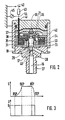
- the electrically controlled valve 2O in the embodiment of a 2/2-way solenoid valve is shown in Fig. 2 in longitudinal section and enlarged.
- the valve 2O can be screwed into the socket 2 with its valve housing 4O and at the same time thus delimits the pump working space 6.
- the connecting line 16 then runs in the screw part 27 which is integral with the valve housing 40 and serves to connect to the housing 1 of the fuel injection pump to the valve seat 17 surrounding the flow opening 46 and from there downstream via a valve chamber 29 and further sections of the connecting line 16 to the supply channel 7.
- a conical or mushroom-shaped section 28 of the valve member 18 cooperates with the valve seat 17, which section is connected to a cylindrical section 30 is guided in a guide bore 31.
- the guide bore 31 is located within a central core 33 which is integral with the valve housing 40 and which is surrounded by a magnet coil 34.
- the cylindrical section 30 of the valve member 18 is electrically insulated from the guide bore 31, which can be done with a corresponding coating 35.
- the valve member 18 is connected to an anchor plate 36.
- a compression spring 37 acting in the valve opening direction is clamped between the anchor plate 36 and the core 33, which brings the armature plate 36 into contact with a stop 39 to limit the stroke of the valve member 18 when the solenoid 34 is not energized.
- the stop 39 is fastened in the metallic valve housing 4O and connected to it in an electrically conductive manner, while the compression spring 37 is electrically separated from the core 33 or the valve housing 4O by insulation 38.
- the solenoid 34 When the solenoid 34 is de-energized, the valve member 18 has electrical contact via the armature plate 36 and the stop 39 with the housing 40.
- the solenoid 34 When the solenoid 34 is energized, the valve member 18 is in the closed position shown in FIG. 2 and then has electrical contact via the mushroom-shaped section 28 and the valve seat 17 to the housing 40.
- an electrically insulated feed line 41 is provided, which is guided in an insulated manner through the housing 40 to the compression spring 37. There is an electrical contact between the electrical supply line 41 and the compression spring 37 and thus via the latter to the armature plate 36 and the valve member 18.
- the supply line 41 is connected to one pole of a measuring voltage source 42 with the interposition of a resistor 43.
- the other pole of the measuring voltage source 42 is connected to the housing 40.
- a measuring voltage is tapped between the connection point 44 of the supply line 41 and the resistor 43 and the housing 40, which is characteristic of the current position of the valve member 18. The voltage tap is symbolized by the measuring instrument 45 in FIG. 2.
- FIG. 3 shows the stroke S or adjustment path of the valve member 18 as a function of time in the upper diagram.
- the control voltage measured by the measuring instrument 45 is at the connection point 44, which forms the output signal 47 of the switch position transmitter 21 in FIG. 1.
- connection to ground is interrupted and the voltage tapped at connection point 44 rises to a value U1 (lower diagram in FIG. 3).
- the stroke of the valve member 18 and thus the closing process of the valve 20 is ended at point BEP (beginning of the injection period).
- the section 28 of the valve member 18 is seated on the valve seat 17, so that contact with ground is restored and the measuring voltage source 42 is short-circuited again.
- the voltage detected by the measuring instrument 45 breaks down again.
- the fuel is injected in the following period, which may already have started in the BSP - BEP area after reaching a certain pressure level.
- the excitation of the magnet coil 34 is switched off.
- the point B ⁇ P start of the opening period
- the valve member 18 begins to lift off from the valve seat 17 under the action of the compression spring 37.
- the voltage tapped at the connection point 44 rises again to the value U1 and does not collapse again until the anchor plate 36 connected to the valve member 18 has reached the stop 39.
- the switch position transmitter 21 thus provides very exact signals for the actual movement of the valve member 18 from its two end positions, the closed position and the open position, regardless of the control time of the energizing pulse of the solenoid 34.
- the latter phase is referred to as the first movement phase, which is evaluated with a first factor, while the aforementioned phase between B ⁇ P and EEP is referred to as the second movement phase and is evaluated with a higher, second factor. Both movement phases therefore go proportionately into the opening time of the valve 20 that is effective for metering the fuel injection quantity.
- the control device 22 can now detect the exact opening and closing course of the valve 20 and use it to calculate the actually metered fuel injection quantity. Variations in design and tolerance as well as drift vibrations and malfunctions of valve 2O can be taken into account, since the exact time of valve closing or valve opening is always recorded. A sticking of the valve member 18 in any position along the stroke can also be detected. E.g. It can be determined from the time sequence of the movement start signals and movement end signals occurring, preferably if these are compared with the time sequence of the control pulse edges driving the valve, whether the functionality of the valve 20 is restricted or not. A functional or non-functional signal is generated in this way. The signals output by the switch position transmitter 21 described can be clearly removed.
- the switch position transmitter 21 is constructed from simple switching elements.
- the stop 39 for the anchor plate 36 can be made of steel. Conductive plastic can also be used for this.
- valve 20 When the valve 20 is used as a so-called metering valve, it is arranged in the supply channel 7, which then replaces the connecting line 16. In this case, reverse switching logic is used.
- the stroke course of the valve member 18 would then have the same course as shown in FIG. 3 in the upper diagram, only the valve would be closed in BSP, open in BEP-B ⁇ P and closed again in EEP.
- These Points then describe accordingly the fuel metering phase in which the pump work space 6 is filled with the metered amount of fuel.
- the solenoid 34 is excited accordingly with different control times or the compression spring 37 is given a different direction of action.
- the fuel injection pump can advantageously also be implemented as a radial piston pump.
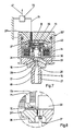
- valve 2O in FIG. 1 shown in longitudinal section in FIG. 4 differs from the valve 2O shown in FIG. 2 only by a different design of the switching position transmitter 21 ⁇ . Except for the missing insulating layers 35 and 38 and a different connection of the supply line 41, the structure of the valve designated 2O ⁇ is identical to the valve 2O described in FIG. 2, so that the same components are provided with the same reference numerals.
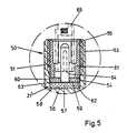
- the switching position transmitter 21 ⁇ shown in FIG. 5 is attached to the stop 39 to limit the stroke of the valve member 18.
- the stop 39 is designed here as a bolt 50, which is screwed with its shaft 51 by means of an external thread 53 in the valve housing 40 and with its head 52 the anchor plate 36 rigidly connected to the valve member 18 faces.
- the shaft 51 has a blind bore 54 which extends axially from the shaft end and has an internal thread 55.
- a disk 57 made of piezoelectric ceramic, hereinafter referred to as piezo disk 57, of the switch position transmitter 21 ⁇ is arranged at the bottom 56 of the bore.
- the piezo disk 57 has metallized electrodes 58, 59 on both end faces.
- the piezo disk 57 lies with the one electrode 58 producing one electrical contact on the bore base 56 and is clamped on the other electrode 59 on the pressure ring 6O made of insulating material on the bore base 56.
- the bracing takes place via a hollow cylindrical locking screw 61 which is screwed into the internal thread 55 and presses with its end-shaped annular surface 62 onto the pressure ring 60.
- a disk-shaped contact ring 63 which is mechanically and electrically connected to a plug contact 64, is arranged between the end face of the pressure ring 60 and the electrode 59 of the piezo disk 57 facing it.
- the plug contact 64 passes through the ring opening of the pressure ring 60 and extends axially in the interior of the locking screw 61.
- the contact ring 63, the plug contact 64 and the pressure ring 60 are designed as a structural unit.
- a plug 65 sits on the plug contact 64 and is connected in an electrically conductive manner to a supply line 66 which is insulated and passed through the valve housing 40.
- the feed line is connected to a connection of a voltage measuring device 67, the other connection of which lies on the valve housing 40.
- the piezo disk 57 of the switch position transmitter 21 ⁇ can also be arranged directly in the head 52 of the bolt 5O instead of near the free end of the shaft 51 of the bolt 5O.
- Diagram a shows the voltage curve of the control pulse applied to the magnet coil 34 for valve control
- diagram b shows the curve of the excitation current of the magnet coil 34
- diagram c shows the voltage curve detected by the voltage measuring device 67 after amplification as the output signal of the switch position transmitter.
- the solenoid 34 is activated by means of the control pulse.
- the valve member 18 hits the valve seat 17.
- the structure-borne sound wave causes a change in the output signal of the switching actuator 21 ⁇ , which can be clearly seen in diagram c in FIG. 6 at the time BEP.
- the magnetic excitation is switched off.
- valve member 18 begins to open and stops at the stop 39 at the time EEP.
- the striking of the anchor plate 36 connected to the valve member 18 on the stop 39 again triggers a structure-borne sound wave, which again mechanically stresses the piezo disk 57 and thereby causes a change in the output signal of the switch position transmitter 21 ⁇ .
- the signal change at time EEP can be clearly seen in diagram c of FIG. 6.
- the control device 22 of the fuel injection device can now, in the same manner as described above, with the aid of the voltage signal output by the voltage measuring device 67 (diagram c in FIG. 6) the exact one Record the opening and closing curve of valve 2O ⁇ and use it to calculate the actually metered fuel injection quantity.
- the stop 39 for limiting the stroke of the valve member 18 is surrounded by an insulated metallic washer 7O arranged in the valve housing 40, which is connected via an electrical lead 71, which is isolated through the valve housing 40, to a connection of a measuring device 72, the other connection of which lies on the valve housing 40 .
- the annular disk 70 together with the anchor plate 36 connected to the valve member 18 forms an annular capacitor, the capacitance of which is proportional to the area of the annular disk 70 and inversely proportional to the distance between the annular disk 70 and the anchor plate 36.
- the measuring device 72 uses known evaluation methods (e.g.
- the valve member 18 is seated on the valve seat 17 and the valve 2O ⁇ is closed.
- the capacitance of the ring capacitor has reached a minimum, and the change in capacitance detected by the measuring device 72 has reached a maximum.
- the maximum of the change in capacity is thus a measure for reaching the closed position of the valve 2O ⁇ .
- the ring capacitor has again reached its greatest capacity.
- the change in capacity detected in the measuring device 72 has again reached a maximum and signals the reaching of the end position of the valve member 18 and thus the open position of the valve 20 ". Since the valve 2O ⁇ also like the other two valves 2O and 2O ⁇ as a control valve in the connecting line 16 from Pump working chamber 6 to the suction chamber 8, the fuel metering phase is initiated when valve 2O ⁇ is closed and the fuel metering phase is ended when valve 2O ⁇ is opened, so that the maximum change in capacity always represents a movement end signal of valve member 18. The first movement end signal thus indicates the closed state and the second End of movement signal indicates the opening state of the valve 20.
- the beginning of the change in capacity characterizes the start of movement of the valve member 18.
- the control device 22 in turn detects the time interval between a first end of movement signal and a subsequent start of movement Signal as actual value for the effective control time of valve 2O ⁇ . During this control time, the valve 2Oclude is kept in its closed state.
- the first movement phase of the valve member 18 between the points BSP and BEP, the so-called switch-on flight time, and the second movement phase between the points B ⁇ P and EEP, the so-called switch-off flight time can also be carried out after a corresponding evaluation a first and a second factor of the effective control time are added.
- the valve 2O ⁇ with the switch position transmitter 21 ⁇ can be used as a so-called metering valve, which is then to be arranged in the supply channel 7 with the elimination of the connecting line 16.
- the first movement end signal (in points BEP) identifies the opening state and the second movement end signal (in points EEP) the closing state of valve 2O ⁇ .
- the effective control time of the valve 2O ⁇ between the first movement end signal (in points BEP) and the following movement start signal (in points B ⁇ P) keeps the valve 2O ⁇ in its open state during the suction stroke of the pump piston 3.
Landscapes
- Engineering & Computer Science (AREA)
- Chemical & Material Sciences (AREA)
- Combustion & Propulsion (AREA)
- Mechanical Engineering (AREA)
- General Engineering & Computer Science (AREA)
- Physics & Mathematics (AREA)
- Electromagnetism (AREA)
- Fuel-Injection Apparatus (AREA)
Claims (14)
- Dispositif d'injection de carburant pour moteurs à combustion interne avec une pompe d'injection de carburant comportant un piston de pompe (3) et une chambre de travail de la pompe (6) délimitée par ce piston, notamment une pompe d'injection de carburant du type pompe d'injection distributrice, avec une soupape (20) disposée sur une canalisation de liaison entre la chambre de travail de la pompe (6) et une chambre basse pression du carburant (8), avec un organe de soupape (18) qui est susceptible d'être amené dans deux positions de commutation, par l'intermédiaire d'un entraînement électrique de commutation, à savoir une position d'ouverture déterminée par une butée sur le boîtier de la soupape et une position de fermeture déterminée par un siège (17) de la soupape, la quantité de carburant arrivant à l'injection par course de refoulement du piston de la pompe, étant alors susceptible d'être déterminée par l'intermédiaire des temps au cours desquels l'organe de soupape se trouve dans des positions de commutation, et avec un dispositif de commande (22) pour commander l'entraînement de commutation de la soupape avec un indicateur (21) relié au dispositif de commande (22) et détectant la commutation de l'organe de soupape (20), indicateur dont la partie mobile est déplacée par l'organe de soupape et engendre les signaux électriques caractéristiques, dont l'intervalle dans le temps est déterminé en tant que valeur réelle, comme mesure de la quantité de carburant injectée, par le dispositif de commande (22) et les temps de commutation de l'organe de soupape (18) sont corrigés par ce dispositif de commande, conformément à la différence entre la valeur réelle et une valeur de consigne prédéfinie par des paramètres de fonctionnement du moteur à combustion interne, dispositif d'injection de carburant caractérisé en ce que l'organe de soupape (18) déclenche respectivement, par son application contre la butée (39) et contre le siège de soupape (17), la délivrance d'un signal de l'indicateur (21) réalisé sous la forme d'un indicateur de position de commutation, cependant que le siège de soupape (17), la butée (39), et l'organe de soupape (18) sont électriquement conducteurs et que l'organe de soupape (18) est guidé dans le boîtier de soupape (40) en étant isolé électriquement vis à vis de celui-ci, et est relié à un pôle d'une source de tension de mesure (42), au pôle opposé de laquelle sont raccordés la butée (39) et le siège de soupape (17).
- Dispositif selon la revendication 1, caractérisé en ce que la butée (39) est constituée par un matériau plastique conducteur et est reliée de façon électriquement conductrice au carter de soupape (40).
- Dispositif d'injection de carburant pour moteurs à combustion interne, avec une pompe d'injection de carburant comportant un piston de pompe (3) et une chambre de travail de la pompe (6) délimitée par ce piston, notamment une pompe d'injection de carburant du type pompe d'injection distributrice, avec une soupape (20') disposée sur une canalisation de liaison entre la chambre de travail de la pompe (6) et une chambre basse pression du carburant (8), avec un organe de soupape (18) qui est susceptible d'être amené dans deux positions de commutation, par l'intermédiaire d'un entraînement électrique de commutation, à savoir une position d'ouverture déterminée par une butée sur le boîtier de la soupape, et une position de fermeture déterminée par un siège (17) de la soupape, la quantité de carburant arrivant à l'injection par course de refoulement du piston de la pompe étant alors susceptible d'être déterminée par l'intermédiaire des temps au cours desquels l'organe de soupape se trouve dans les positions de commutation, et avec un dispositif de commande (22) pour commander l'entraînement de commutation de la soupape avec un indicateur (21') relié au dispositif de commande (22) et détectant la commutation de l'organe de soupape (20'), indicateur dont la partie mobile est déplacée par l'organe de soupape et engendre les signaux électriques caracteristiques, dont l'intervalle dans le temps est déterminé en tant que valeur réelle, comme mesure de la quantité de carburant à injecter, par le dispositif de commande (22) et les temps de commutation de l'organe de soupape (18) sont corrigés par ce dispositif de commande conformément à la différence entre la valeur réelle et une valeur de consigne prédéfinie par des paramètres de fonctionnement du moteur à combustion interne, dispositif d'injection de carburant caractérisé en ce que l'organe de soupape (18) déclenche respectivement, par son application contre la butée (39) et contre le siège de soupape (17) la délivrance d'un signal de l'indicateur (21') réalisé sous la forme d'un indicateur de position de commutation, cependant que la soupape (20') comporte un boîtier métallique (40), dans lequel sont disposés le siège de soupape (17) et la butée (39), et dans lequel l'organe de sou-pape (18) est guidé de façon à pouvoir se déplacer axialement entre le siège de soupape (17) et la butée (39), et en ce que, contre cette butée (39) est vissé, en tant que partie à poste fixe de l'indicateur de position de commutation, un disque (57) en céramique piézo-électrique détectant le bruit de structure lors de la percussion de l'organe de soupape sur le siège de soupape et la butée, ce disque portant respectivement sur ses deux faces frontales une électrode métallique (58, 59), lesquelles sont reliées à un appareil de mesure de la tension (67).
- Dispositif selon la revendication 3, caractérisé en ce que l'une (58) des électrodes est reliée de façon électriquement conductrice à la butée (39), tandis que l'autre électrode (59) est reliée de façon électriquement conductrice à un contact d'enfichage (64) isolé vis à vis de la butée (39) et du boîtier de soupape (40), et en ce que le boîtier de soupape (40) est raccordé à l'un des pôles de l'appareil de mesure de la tension (67), tandis que le contact d'enfichage (64) est raccordé à l'autre pôle de cet appareil.
- Dispositif selon la revendication 4, caractérisé en ce que la butée (39) est réalisée sous la forme d'un goujon (50) fixé dans le boîtier de soupape (40) avec un perçage borgne axial (54) comportant un filetage interne (55), en ce que le disque piézoélectrique (57) s'applique avec une de ses électrodes (58) sur le fond (56) du perçage s'étendant radialement et est pressé sur celui-ci, par l'intermédiaire d'un anneau de pressage (60), par une vis de fixation (61) cylindrique creuse vissée dans le perçage borgne (54), et en ce que le contact d'enfichage (64) relié à l'autre électrode (59) passe à travers l'ouverture annulaire de l'anneau de pressage (60) et s'étend axialement à l'intérieur de la vis de fixation (61).
- Dispositif selon la revendication 5, caractérisé en ce qu'entre la face frontale de l'anneau de pressage (60) et l'électrode (59), tournée vers cet anneau, du disque piézo-électrique (57) est disposé un anneau de contact (63) en forme de disque relié au contact d'enfichage (64), et en ce que l'anneau de pressage (60) et l'anneau de contact (63) forment avec le contact d'enfichage (64) une unité constitutive.
- Dispositif selon la revendication 5 ou la revendication 6, caractérisé en ce que le disque piézo-électrique (57) est disposé à une extrémité du goujon (50).
- Dispositif d'injection de carburant pour moteurs à combustion interne avec une pompe d'injection de carburant comportant un piston de pompe (3) et une chambre de travail de la pompe (6) délimitée par ce piston, notamment une pompe d'injection de carburant du type pompe d'injection distributrice, avec une soupape (20") disposée sur une canalisation de liaison entre la chambre de travail de la pompe (6) et une chambre basse pression du carburant (8), avec un organe de soupape (18) qui est susceptible d'être amené dans deux positions de commutation par l'intermédiaire d'un entraînement électrique de commutation, à savoir une position d'ouverture déterminée par une butée sur le boîtier de la soupape et une position de fermeture déterminée par un siège (17) de la soupape, la quantité de carburant arrivant à l'injection par course de refoulement du piston de la pompe étant alors susceptible d'être déterminée par l'intermédiaire des temps au cours desquels l'organe de soupape se trouve dans des positions de commutation, et avec un dispositif de commande (22) pour commander l'entraînement de commutation de la soupape, avec un indicateur (21") relié au dispositif de commande (22) et détectant la commutation de l'organe de soupape (20"), indicateur dont la partie mobile est déplacée par l'organe de soupape et engendre les signaux électriques caractéristiques, dont l'intervalle dans le temps est déterminé en tant que valeur réelle, comme mesure de la quantité de carburant à injecter, par le dispositif de commande (22) et les temps de commutation de l'organe de soupape (18) sont corrigés par ce dispositif de commande conformément à la différence entre la valeur réelle et une valeur de consigne prédéfinie par des paramètres de fonctionnement du moteur à combustion interne, dispositif d'injection de carburant caractérisé en ce que l'organe de soupape (18) déclenche respectivement par son application contre la butée (39) et contre le siège de soupape (17) la délivrance d'un signal de l'indicateur (21") réalisé sous la forme d'un indicateur de position de commutation, cependant que la soupape (20") comporte un boîtier métallique (40), dans lequel sont disposés le siège de soupape (17) et la butée (39), et dans lequel l'organe de soupape (18) est guidé de façon à pouvoir se déplacer axialement entre le siège de soupape (17) et la butée (39), en ce que l'organe de soupape (18) à son extrémité opposée au siège de soupape (17) porte un disque métallique (36), et en ce que la butée (39) est entourée par un disque annulaire métallique isolé (70) en tant que partie à poste fixe de l'indicateur de commutation, et forme avec le disque métallique (36) en tant que partie mobile de l'indicateur de position de commutation, un condensateur annulaire, qui est relié avec un dispositif de mesure (72) pour mesurer les capacités du condensateur annulaire caractérisant les positions de l'organe de soupape.
- Dispositif selon la revendication 8, caractérisé en ce que le disque annulaire (70) est fixé dans le boîtier de soupape (40) en étant électriquement isolé, et est relié de façon électriquement conductrice à une liaison de raccordement (71), passant sous isolation à travers le carter de soupape (40), pour le dispositif de mesure (72).
- Dispositif selon l'une des précédentes revendications, caractérisé en ce que l'indicateur de position de commutation (21; 21'; 21") donne en tant que signal de début du déplacement (BSP, BÖP) le début du déplacement de l'organe de la soupape (18) lorsque celui-ci décolle du siège de soupape ou de la butée, et donne en tant que signal de fin de déplacement (BEP, EEP) la fin du déplacement de l'organe de soupape (18) lorsque celui-ci vient s'appliquer sur le siège de soupape ou la butée, et en ce que le dispositif de commande (22) détecte l'intervalle de temps entre un premier signal de fin de déplacement (BEP) et un signal de début de déplacement (BÖP) venant à la suite en tant que valeurs réelles pour le temps de commande utile pour le dosage de la soupape (20, 20', 20") et pour la quantité de carburant arrivant effectivement pour l'injection.
- Dispositif selon la revendication 10, caractérisé en ce que le dispositif de commande mesure en tant que seconde phase de déplacement le temps entre l'apparition d'un second signal de début du déplacement (BÖP) et un signal de fin de déplacement (EEP) venant à la suite, et ajoute ce temps, après multiplication par un second facteur, au temps de commande utile pour le dosage pour la quantité de carburant arrivant effectivement pour l'injection.
- Dispositif selon la revendication 10 ou la revendication 11, caractérisé en ce que le dispositif de commande (22) mesure en tant que première phase de déplacement, le temps entre l'apparition d'un signal de début de déplacement (BSP) et un premier signal de fin de déplacement (BEP) venant à la suite, et ajoute ce temps, après multiplication par un premier facteur, au temps de commande utile pour le dosage pour la quantité de carburant arrivant effectivement pour l'injection.
- Dispositif selon une des revendications 10 ou 11, caractérisé en ce que le premier signal de fin de déplacement (BEP) caractérise l'état de fermeture de la soupape (20; 20'; 20") tandis que le second signal de fin de déplacement (EEP) caractérise l'état d'ouverture de la soupape, et en ce que la soupape (20; 20'; 20") est commandée de façon que le temps de commande utile pour le dosage maintient la soupape (20; 20'; 20") dans la position de fermeture pendant la course de refoulement du piston de la pompe.
- Dispositif selon une des revendications 10 ou 11, caractérisé en ce que le premier signal de fin de déplacement (BEP) caractérise l'état d'ouverture de la soupape (20; 20'; 20") tandis que le second signal de fin de déplacement (EEP) caractérise l'état de fermeture de la soupape, et en ce que la soupape (20; 20'; 20") est commandée de façon que le temps de commande utile pour le dosage maintien la soupape (20; 20'; 20") dans son état d'ouverture pendant la course d'aspiration du piston de la pompe.
Applications Claiming Priority (4)
| Application Number | Priority Date | Filing Date | Title |
|---|---|---|---|
| DE3612152 | 1986-04-10 | ||
| DE3612152 | 1986-04-10 | ||
| DE19863633107 DE3633107A1 (de) | 1986-04-10 | 1986-09-30 | Kraftstoffeinspritzvorrichtung fuer brennkraftmaschinen |
| DE3633107 | 1986-09-30 |
Publications (2)
| Publication Number | Publication Date |
|---|---|
| EP0241697A1 EP0241697A1 (fr) | 1987-10-21 |
| EP0241697B1 true EP0241697B1 (fr) | 1991-03-27 |
Family
ID=25842792
Family Applications (1)
| Application Number | Title | Priority Date | Filing Date |
|---|---|---|---|
| EP19870103241 Expired - Lifetime EP0241697B1 (fr) | 1986-04-10 | 1987-03-06 | Dispositif d'injection du combustible pour moteurs à combustion interne |
Country Status (4)
| Country | Link |
|---|---|
| US (1) | US4793313A (fr) |
| EP (1) | EP0241697B1 (fr) |
| JP (1) | JP2585581B2 (fr) |
| DE (2) | DE3633107A1 (fr) |
Families Citing this family (43)
| Publication number | Priority date | Publication date | Assignee | Title |
|---|---|---|---|---|
| DE3711744A1 (de) * | 1987-04-07 | 1988-10-27 | Bosch Gmbh Robert | Verfahren und vorrichtung zur steuerung der kraftstoffeinspritzmenge |
| DE3730523A1 (de) * | 1987-09-11 | 1989-03-30 | Bosch Gmbh Robert | Verfahren und einrichtung zur detektion der schaltzeiten von magnetventilen |
| DE3816165A1 (de) * | 1988-05-11 | 1989-11-23 | Bosch Gmbh Robert | Steuersystem fuer eine dieselbrennkraftmaschine |
| DE3838599A1 (de) * | 1988-11-15 | 1990-05-17 | Bosch Gmbh Robert | Magnetventil, insbesondere fuer kraftstoffeinspritzpumpen |
| DE3943245A1 (de) * | 1989-12-29 | 1991-07-04 | Bosch Gmbh Robert | Kraftstoffeinspritzpumpe |
| IT1241144B (it) * | 1990-05-17 | 1993-12-29 | Vittorio Stiatti | Elettromagnete per elettrovalvole |
| US5230613A (en) * | 1990-07-16 | 1993-07-27 | Diesel Technology Company | Common rail fuel injection system |
| US5133645A (en) * | 1990-07-16 | 1992-07-28 | Diesel Technology Corporation | Common rail fuel injection system |
| DE4024369A1 (de) * | 1990-08-01 | 1992-02-06 | Daimler Benz Ag | Verfahren zur regelung der den zylindern einer brennkraftmaschine zugefuehrten gemisch- bzw. kraftstoffmenge |
| US6394072B1 (en) * | 1990-08-31 | 2002-05-28 | Yamaha Hatsudoki Kabushiki Kaisha | Fuel injection device for engine |
| US5738071A (en) * | 1991-05-22 | 1998-04-14 | Wolff Controls Corporation | Apparatus and method for sensing movement of fuel injector valve |
| JPH05248300A (ja) * | 1992-03-04 | 1993-09-24 | Zexel Corp | 燃料噴射装置 |
| US5325837A (en) * | 1992-11-19 | 1994-07-05 | Robert Bosch Gmbh | Fuel injection apparatus for internal combustion engines |
| US5345916A (en) * | 1993-02-25 | 1994-09-13 | General Motors Corporation | Controlled fuel injection rate for optimizing diesel engine operation |
| DE4307111A1 (de) * | 1993-03-06 | 1994-09-08 | Bosch Gmbh Robert | Kraftstoffeinspritzpumpe |
| DE4329976A1 (de) * | 1993-09-04 | 1995-03-09 | Bosch Gmbh Robert | Verfahren zur Hubmessung und Einstellung eines Ventils |
| US5593134A (en) * | 1995-02-21 | 1997-01-14 | Applied Power Inc. | Magnetically assisted piezo-electric valve actuator |
| US5630440A (en) * | 1995-02-21 | 1997-05-20 | Applied Power Inc. | Piezo composite sheet actuated valve |
| US5551406A (en) * | 1995-05-19 | 1996-09-03 | Siemens Electric Limited | Canister purge system having improved purge valve |
| JPH11505584A (ja) * | 1995-05-19 | 1999-05-21 | ジーメンス エレクトリック リミテッド | 改良されたパージ・バルブを有するキャニスタ・パージ装置 |
| US5775355A (en) * | 1996-03-11 | 1998-07-07 | Robert Bosch Gmbh | Method for measuring the lift of a valve needle of a valve and for adjusting the volume of media flow of the valve |
| US5747684A (en) * | 1996-07-26 | 1998-05-05 | Siemens Automotive Corporation | Method and apparatus for accurately determining opening and closing times for automotive fuel injectors |
| US6247456B1 (en) | 1996-11-07 | 2001-06-19 | Siemens Canada Ltd | Canister purge system having improved purge valve control |
| US6102364A (en) * | 1997-07-30 | 2000-08-15 | Siemens Canada Limited | Control accuracy of a pulse-operated electromechanical device |
| EP1157205B1 (fr) * | 1999-03-01 | 2002-09-11 | Siemens Aktiengesellschaft | Systeme et procede de regulation d'une soupape de commande de systeme d'injection pour moteur diesel |
| US6836056B2 (en) | 2000-02-04 | 2004-12-28 | Viking Technologies, L.C. | Linear motor having piezo actuators |
| DE10007691B4 (de) * | 2000-02-19 | 2006-10-26 | Robert Bosch Gmbh | Verfahren und Vorrichtung zum Speichern und/oder Auslesen von Daten eines Kraftstoffzumesssystems |
| JP3842002B2 (ja) * | 2000-03-01 | 2006-11-08 | 三菱電機株式会社 | 可変吐出量燃料供給装置 |
| US6437226B2 (en) | 2000-03-07 | 2002-08-20 | Viking Technologies, Inc. | Method and system for automatically tuning a stringed instrument |
| US6548938B2 (en) | 2000-04-18 | 2003-04-15 | Viking Technologies, L.C. | Apparatus having a pair of opposing surfaces driven by a piezoelectric actuator |
| US6717332B2 (en) | 2000-04-18 | 2004-04-06 | Viking Technologies, L.C. | Apparatus having a support structure and actuator |
| US6879087B2 (en) | 2002-02-06 | 2005-04-12 | Viking Technologies, L.C. | Apparatus for moving a pair of opposing surfaces in response to an electrical activation |
| US6759790B1 (en) | 2001-01-29 | 2004-07-06 | Viking Technologies, L.C. | Apparatus for moving folded-back arms having a pair of opposing surfaces in response to an electrical activation |
| DE10119984A1 (de) * | 2001-04-24 | 2002-10-31 | Bosch Gmbh Robert | Kraftstoffeinspritzeinrichtung für eine Brennkraftmaschine |
| WO2004001871A2 (fr) * | 2002-06-21 | 2003-12-31 | Viking Technologies, L.C. | Moteur piezo-electrique monobloc |
| US7368856B2 (en) | 2003-04-04 | 2008-05-06 | Parker-Hannifin Corporation | Apparatus and process for optimizing work from a smart material actuator product |
| US20070030618A1 (en) * | 2003-07-31 | 2007-02-08 | Micha Heinz | Method and device for producing and/or adjusting and electromagnetically controllable actuator |
| CN100408399C (zh) * | 2003-07-31 | 2008-08-06 | 大陆-特韦斯贸易合伙股份公司及两合公司 | 用于制造和/或调节可电磁控制的致动器的方法和设备 |
| DE102005007327B4 (de) * | 2005-02-17 | 2010-06-17 | Continental Automotive Gmbh | Schaltungsanordnung und Verfahren zum Betreiben einer Injektoranordnung |
| JP4050287B2 (ja) * | 2005-08-10 | 2008-02-20 | 三菱電機株式会社 | 内燃機関の省エネ方式の高圧燃料供給制御装置 |
| DE102010027806B4 (de) * | 2010-04-15 | 2024-01-18 | Robert Bosch Gmbh | Verfahren zum Betreiben einer Brennkraftmaschine, bei dem eine Größe ermittelt wird |
| DE102010021169B4 (de) * | 2010-05-21 | 2012-03-08 | Continental Automotive Gmbh | Verfahren und Vorrichtung zur Ermittlung des tatsächlichen Einspritzbeginns eines Piezo-Kraftstoff-Einspritzventils |
| EP3263869B1 (fr) | 2016-06-30 | 2023-05-03 | Hamilton Sundstrand Corporation | Valve doseuse |
Family Cites Families (18)
| Publication number | Priority date | Publication date | Assignee | Title |
|---|---|---|---|---|
| US3244663A (en) * | 1958-05-08 | 1966-04-05 | Bendix Corp | High temperature resistant rubber-like composition |
| US3779225A (en) * | 1972-06-08 | 1973-12-18 | Bendix Corp | Reciprocating plunger type fuel injection pump having electromagnetically operated control port |
| IT1050083B (it) * | 1974-12-21 | 1981-03-10 | Cav Ltd | Ugelli di iniezione di combustibile |
| DE2925418A1 (de) * | 1979-06-23 | 1981-01-29 | Bosch Gmbh Robert | Kraftstoffeinspritzpumpe fuer brennkraftmaschinen |
| JPS56113044A (en) * | 1980-02-13 | 1981-09-05 | Nissan Motor Co Ltd | Injection timing sensor |
| DE3047078A1 (de) * | 1980-12-13 | 1982-07-15 | Robert Bosch Gmbh, 7000 Stuttgart | Verfahren zur bestimmung des foerderbeginns bei einspritzpumpen |
| DE3123325A1 (de) * | 1981-06-12 | 1982-12-30 | Robert Bosch Gmbh, 7000 Stuttgart | Kraftstoffeinspritzeinrichtung fuer brennkraftmaschinen |
| JPS5827882A (ja) * | 1981-08-11 | 1983-02-18 | Mitsubishi Electric Corp | 内燃機関の燃料制御装置 |
| JPS5915644A (ja) * | 1982-07-19 | 1984-01-26 | Nissan Motor Co Ltd | 燃料噴射式内燃機関の燃料噴射量検出装置および電子燃料噴射量制御装置 |
| JPS5951139A (ja) * | 1982-09-17 | 1984-03-24 | Nippon Soken Inc | 燃料供給装置 |
| GB2129163B (en) * | 1982-10-21 | 1986-07-30 | Lucas Ind Plc | Liquid fuel pumping apparatus |
| DE3243348A1 (de) * | 1982-11-24 | 1984-05-24 | Robert Bosch Gmbh, 7000 Stuttgart | Kraftstoffeinspritzpumpe |
| DE3302292A1 (de) * | 1983-01-25 | 1984-07-26 | Klöckner-Humboldt-Deutz AG, 5000 Köln | Elektromagnetisch betaetigbares steuerventil fuer kraftstoffeinspritzvorrichtungen |
| JPS59160040A (ja) * | 1983-03-01 | 1984-09-10 | Diesel Kiki Co Ltd | 電子制御式燃料噴射ポンプ |
| JPS6066844U (ja) * | 1983-10-14 | 1985-05-11 | 株式会社ボッシュオートモーティブ システム | 分配型燃料噴射ポンプの噴射率制御装置 |
| DE3343481A1 (de) * | 1983-12-01 | 1985-06-13 | Robert Bosch Gmbh, 7000 Stuttgart | Korrektureinrichtung fuer ein kraftstoffzumesssystem einer brennkraftmaschine |
| JPS60162238U (ja) * | 1984-04-05 | 1985-10-28 | 株式会社ボッシュオートモーティブ システム | 燃料噴射装置 |
| DE3581160D1 (de) * | 1984-09-14 | 1991-02-07 | Bosch Gmbh Robert | Elektrisch gesteuerte kraftstoffeinspritzpumpe fuer brennkraftmaschinen. |
-
1986
- 1986-09-30 DE DE19863633107 patent/DE3633107A1/de not_active Withdrawn
-
1987
- 1987-03-06 EP EP19870103241 patent/EP0241697B1/fr not_active Expired - Lifetime
- 1987-03-06 DE DE8787103241T patent/DE3768842D1/de not_active Expired - Lifetime
- 1987-03-10 US US07/024,196 patent/US4793313A/en not_active Expired - Fee Related
- 1987-04-09 JP JP62085903A patent/JP2585581B2/ja not_active Expired - Fee Related
Also Published As
| Publication number | Publication date |
|---|---|
| DE3768842D1 (de) | 1991-05-02 |
| US4793313A (en) | 1988-12-27 |
| JPS62243963A (ja) | 1987-10-24 |
| JP2585581B2 (ja) | 1997-02-26 |
| DE3633107A1 (de) | 1987-10-15 |
| EP0241697A1 (fr) | 1987-10-21 |
Similar Documents
| Publication | Publication Date | Title |
|---|---|---|
| EP0241697A1 (fr) | Dispositif d'injection du combustible pour moteurs à combustion interne | |
| DE2342109C2 (de) | Elektromechanisch gesteuertes Kraftstoffeinspritzventil für Brennkraftmaschinen | |
| EP1151190B1 (fr) | Soupape d'injection de carburant | |
| EP0444055B1 (fr) | Soupape magnetique, notamment pour pompes d'injection de carburant | |
| EP0745764B1 (fr) | Soupape d'injection de combustible pour moteurs à combustion interne | |
| EP0823017B1 (fr) | Procede de pilotage de la bobine d'excitation d'une pompe a piston alternatif et a commande electromagnetique | |
| DE69304234T2 (de) | Kraftstoff-Einspritzvorrichtung | |
| WO1987005662A1 (fr) | Procede de commande du temps d'excitation de systemes electromagnetiques, en particulier de soupapes electromagnetiques dans des moteurs a combustion interne | |
| DE2815849C2 (de) | Elektromagnetisch betätigte Gaswechselventile für Kolbenmaschinen | |
| DE2126653A1 (de) | Kraftstoffeinspritzeinrichtung für Brennkraftmaschinen | |
| EP1157205A1 (fr) | Systeme et procede de regulation d'une soupape de commande de systeme d'injection pour moteur diesel | |
| EP1108120B1 (fr) | Dispositif pour commander un appareil de reglage | |
| DE19880737B4 (de) | Verfahren zur Funktionsüberwachung eines elektromagnetischen Aktuators | |
| DE102004058971B4 (de) | Verfahren zum Steuern eines piezoelektrischen Aktors und Steuereinheit zum Steuern eines piezoelektrischen Aktors | |
| DE3600113C2 (fr) | ||
| EP0182109B1 (fr) | Electrovanne pour le réglage du fluide | |
| DD147387A5 (de) | Elektronisch geregelte einspritzanlage mit pumpe-duesen-einrichtung | |
| EP0356469B1 (fr) | Pompe d'injection de carburant pour moteurs a combustion interne | |
| DE2946671C2 (fr) | ||
| DE3601710C2 (de) | Kraftstoffeinspritzvorrichtung für Brennkraftmaschinen | |
| DE3338297C2 (fr) | ||
| EP0309501B1 (fr) | Pompe d'Injection à Combustible pour des Moteurs à Combustion Interne | |
| DE4018320C2 (de) | Ansteuerschaltung für einen elektromagnetischen Verbraucher | |
| DE1176422B (de) | Elektrisch betaetigte Kraftstoffeinspritzanlage fuer Brennkraftmaschinen | |
| EP0945610A2 (fr) | Méthode et dispositif pour commuter une inductance |
Legal Events
| Date | Code | Title | Description |
|---|---|---|---|
| PUAI | Public reference made under article 153(3) epc to a published international application that has entered the european phase |
Free format text: ORIGINAL CODE: 0009012 |
|
| AK | Designated contracting states |
Kind code of ref document: A1 Designated state(s): DE FR GB IT |
|
| 17P | Request for examination filed |
Effective date: 19880315 |
|
| 17Q | First examination report despatched |
Effective date: 19880728 |
|
| GRAA | (expected) grant |
Free format text: ORIGINAL CODE: 0009210 |
|
| AK | Designated contracting states |
Kind code of ref document: B1 Designated state(s): DE FR GB IT |
|
| ET | Fr: translation filed | ||
| GBT | Gb: translation of ep patent filed (gb section 77(6)(a)/1977) | ||
| REF | Corresponds to: |
Ref document number: 3768842 Country of ref document: DE Date of ref document: 19910502 |
|
| ITF | It: translation for a ep patent filed | ||
| PLBE | No opposition filed within time limit |
Free format text: ORIGINAL CODE: 0009261 |
|
| RAP4 | Party data changed (patent owner data changed or rights of a patent transferred) |
Owner name: ROBERT BOSCH GMBH |
|
| PGFP | Annual fee paid to national office [announced via postgrant information from national office to epo] |
Ref country code: GB Payment date: 19920306 Year of fee payment: 6 |
|
| 26N | No opposition filed | ||
| PGFP | Annual fee paid to national office [announced via postgrant information from national office to epo] |
Ref country code: FR Payment date: 19920330 Year of fee payment: 6 |
|
| PG25 | Lapsed in a contracting state [announced via postgrant information from national office to epo] |
Ref country code: GB Effective date: 19930306 |
|
| GBPC | Gb: european patent ceased through non-payment of renewal fee |
Effective date: 19930306 |
|
| PG25 | Lapsed in a contracting state [announced via postgrant information from national office to epo] |
Ref country code: FR Effective date: 19931130 |
|
| REG | Reference to a national code |
Ref country code: FR Ref legal event code: ST |
|
| PGFP | Annual fee paid to national office [announced via postgrant information from national office to epo] |
Ref country code: DE Payment date: 19960528 Year of fee payment: 10 |
|
| PG25 | Lapsed in a contracting state [announced via postgrant information from national office to epo] |
Ref country code: DE Effective date: 19971202 |
|
| PG25 | Lapsed in a contracting state [announced via postgrant information from national office to epo] |
Ref country code: IT Free format text: LAPSE BECAUSE OF NON-PAYMENT OF DUE FEES;WARNING: LAPSES OF ITALIAN PATENTS WITH EFFECTIVE DATE BEFORE 2007 MAY HAVE OCCURRED AT ANY TIME BEFORE 2007. THE CORRECT EFFECTIVE DATE MAY BE DIFFERENT FROM THE ONE RECORDED. Effective date: 20050306 |