EP0823286A2 - Méthode et arrangement d'injection pour transporter des matériaux en particules - Google Patents
Méthode et arrangement d'injection pour transporter des matériaux en particules Download PDFInfo
- Publication number
- EP0823286A2 EP0823286A2 EP97109161A EP97109161A EP0823286A2 EP 0823286 A2 EP0823286 A2 EP 0823286A2 EP 97109161 A EP97109161 A EP 97109161A EP 97109161 A EP97109161 A EP 97109161A EP 0823286 A2 EP0823286 A2 EP 0823286A2
- Authority
- EP
- European Patent Office
- Prior art keywords
- injector
- gas flow
- conveying
- gas
- powder
- Prior art date
- Legal status (The legal status is an assumption and is not a legal conclusion. Google has not performed a legal analysis and makes no representation as to the accuracy of the status listed.)
- Granted
Links
Images

Classifications
-
- B—PERFORMING OPERATIONS; TRANSPORTING
- B05—SPRAYING OR ATOMISING IN GENERAL; APPLYING FLUENT MATERIALS TO SURFACES, IN GENERAL
- B05C—APPARATUS FOR APPLYING FLUENT MATERIALS TO SURFACES, IN GENERAL
- B05C19/00—Apparatus specially adapted for applying particulate materials to surfaces
- B05C19/06—Storage, supply or control of the application of particulate material; Recovery of excess particulate material
-
- B—PERFORMING OPERATIONS; TRANSPORTING
- B05—SPRAYING OR ATOMISING IN GENERAL; APPLYING FLUENT MATERIALS TO SURFACES, IN GENERAL
- B05B—SPRAYING APPARATUS; ATOMISING APPARATUS; NOZZLES
- B05B7/00—Spraying apparatus for discharge of liquids or other fluent materials from two or more sources, e.g. of liquid and air, of powder and gas
- B05B7/14—Spraying apparatus for discharge of liquids or other fluent materials from two or more sources, e.g. of liquid and air, of powder and gas designed for spraying particulate materials
- B05B7/1404—Arrangements for supplying particulate material
Definitions
- the invention relates to a method for funding a powdery good according to the preamble of Claim 1 and an injector arrangement according to the preamble of claim 7. Furthermore, the invention relates to a Use of the injector arrangement according to claim 11.
- the setting of conveying air and dosing air which is a conventional one Compressed air source are removed so far either through separate control valves or through two valves arranged on a common shaft, see above that only one adjustment knob for adjusting both valves had to be operated.
- the powder-air mixture is a relative cover a long route to the coating point must (e.g. a path of 1 meter or more) or where a very homogeneous powder-air mixture is required has the previous setting of conveying air and dosing air proven to be very difficult.
- the can bodies are promoted e.g. at a rate of 18 doses per second (or at one Standard can size with approx. 100 m / min), which is only possible short-term fluctuation of the homogeneity of the powder-air mixture or the absolute amount of powder in one large number of insufficiently coated cans can.
- the invention is therefore based on the object to enable coating by means of an injector, where these disadvantages do not occur and in which even in very delicate conditions, especially in the welding seam coating of can frames, excellent coating quality can be achieved.
- This task is carried out in a process of initially mentioned type solved in that the second Gas flow is fed into the intake area.
- Effective vacuum in the suction area changed so that by the gas flow the amount of the powder sucked in can be determined.
- the amount of feed gas can remain unchanged. It has shown, that in this way an even and stable Delivery of the powder also achieved via long lines can be.
- the gas flow is in the same Direction as the conveying gas flow is introduced into the intake space and more preferably by an annular one Gap around the nozzle of the conveying gas flow, so that this is surrounded by the gas flow.
- an introduction to Gas flow transversely to the conveying gas flow i.e. at an angle to it or at a 90 ° angle is possible.
- the task begins with an arrangement of the mentioned type by the characteristic features of claim 7 solved.
- the method is preferred or the arrangement when coating can frames used for another purpose and for another good to be funded is also possible.
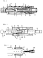
- the example of a well-known injector Injector 1 of FIG. 1 shown according to the prior art has a housing 12.
- the injector room 5 formed, into which the nozzle 4 of the injector protrudes.
- the nozzle 4 with gas in usually fed with compressed air, this compressed air flow forms the conveying air flow.
- the injector room 5 opens a connection 6, through which from a reservoir (not shown) the goods to be funded in the injector room is delivered, in which due to the Conveying air jet there is a negative pressure. That to be funded
- the flow of conveying air entrains well.
- the conveying air flow passes through a sleeve 7.
- connection 8 for the dosing gas in the housing 12 is also usually compressed air is.
- the metering air is the room 10 fed into which the conveying air flow also enters. The both air flows combine and leave the injector 1 through the connector 11 to which a line is connected, the powder-air mixture to the application site leads.
- the coating powder through the injector with Air pressure (e.g. in the range of 6 to 10 bar) in one line promoted in a known manner in the round apparatus enters the can welding machine, the welding area happens and then flows into a nozzle that the Powder-air mixture on the inside of the can weld sprayed on to coat them.
- the coating powder usually electrostatically charged.
- the coating powder becomes a coherent after cooling solid seam coating achieved.
- Corresponding coating powder are known and commercially available and the coating process is known as such. As before mentioned is the setting of conveying air and dosing air very delicate, so enough powder homogeneous distributed at sufficient speed (approx. 12 m / sec) the nozzle is conveyed to an even coating to reach.
- FIG. 2 now shows an injector arrangement as Embodiment of the invention or for explanation of the inventive method.
- an injector 21 provided with a housing 22.
- the injector room 25 formed in the nozzle 24 of the injector protrudes.
- the nozzle 24 is connected via the connection 23 fed with the conveying gas stream, usually from a Compressed air source 30 by means of a line 32, which in Figure 2 are only indicated schematically.
- the injector room opens a connection opening through which a storage container, not shown, the powder to be conveyed is delivered into room 25.
- the injector room 25 there is a negative pressure due to the conveying gas flow, which sucks in the powder to be conveyed, and this becomes entrained by the conveying gas flow.
- the conveying gas flow passes with the powder through a connector 31 on which the line 33 is connected to the powder-air mixture leads to the application site, preferably how already described at the seam area of welded Can frames.
- a second gas stream introduced into the suction area of the injector. in the 2 is a connection 36 provided in the injector housing 22, on which one is not shown gas line or compressed air line connected is.
- This line can be powered from the same source 30 be.
- the connection leads 36 to a part of the Connection 23 circumferential annular space 37, from which a annular gap 38 leads into space 25.
- the gap is formed in the example shown by a sleeve 39, which are at a predetermined distance from the front ones Surrounds the nozzle-containing part of the connector 23.
- the gap 38 in the gas flow 41 entering the injector space surrounds the conveying gas flow 40 ( Figure 3).
- the gas flow Affects the amount of powder sucked into the injector chamber 25, with more air supply in the gas stream 41 the Amount of the suctioned or conveyed with the injector Powder reduced and less air supply to stream 41 the amount of powder delivered increases.
- hiring the air supply at connection 36 or into the room 25 can thus with no change in the conveying gas flow delivered powder quantity can be set.
- the as Example shown arrangement can by a supply of approx. 0% to 15% air as gas flow 41 to that as 100% assumed gas flow 40 a sufficient variation the amount of powder conveyed can be achieved.
- the funded The amount is 100% powder with 0% gas flow 41 and approx.
- FIG 4 shows schematically a pneumatic diagram with the injector 21 shown therein as a block with the Conveying air connection 23 and the gas flow connection 36
- Conveying air and the gas stream air come from one only schematically illustrated compressed air source 30 to which via a line 45 a control valve 46 is connected, the a constant amount of air at its outlet line 47 delivers.
- the amount of air can be controlled by an electrical control signal via the control line 48 from a controller (not shown) can be specified.
- the valve 46 holds then the amount of air emitted by him automatically.
- a valve also known as a mass controller e.g. the mass flow controller type F 201 C from Bronkhorst, the Netherlands.
- a switchable Valve 50 may be arranged as the main valve through which the air supply to the conveying air connection 23 of the injector can be switched on and off.
- the mass controller 46 The air volume delivered then passes via line 51 and Check valve 52 to the supply air connection 23 of the injector 21. Branches upstream of the control valve 46 for the conveying air a line 54 to a flow meter 55 from a Has adjusting member 56, with which the amount of passed Compressed air is adjustable.
- controller 55 can a commercially available flow meter from Vögtlin AG, Switzerland. With the adjusting member 56 the amount of air emitted is set, which is above the Line 57 arrives at the connection 36 of the injector 21 and there determines the amount of powder as gas stream 41.
- Naturally Modifications of these are only to be understood as an example pneumatic arrangement possible.
- on the control valve 46 can be dispensed with when the conveyed air quantity from the source 30 is sufficiently constant.
- a purge air line 59 can be provided if it is not in operation be through which a pressure regulator 60 and a main valve 61 via lines 62 and 63 purge air is conductive in the injector.
- the supply of the gas flow 41 into the injector space 25 can also cross, i.e. at an angle or at a 90 ° angle to the conveying air flow.
Landscapes
- Nozzles (AREA)
- Air Transport Of Granular Materials (AREA)
- Application Of Or Painting With Fluid Materials (AREA)
- Coating Apparatus (AREA)
- Jet Pumps And Other Pumps (AREA)
Applications Claiming Priority (3)
| Application Number | Priority Date | Filing Date | Title |
|---|---|---|---|
| CH193696 | 1996-08-07 | ||
| CH193696 | 1996-08-07 | ||
| CH1936/96 | 1996-08-07 |
Publications (3)
| Publication Number | Publication Date |
|---|---|
| EP0823286A2 true EP0823286A2 (fr) | 1998-02-11 |
| EP0823286A3 EP0823286A3 (fr) | 1998-05-13 |
| EP0823286B1 EP0823286B1 (fr) | 2003-01-02 |
Family
ID=4222073
Family Applications (1)
| Application Number | Title | Priority Date | Filing Date |
|---|---|---|---|
| EP97109161A Expired - Lifetime EP0823286B1 (fr) | 1996-08-07 | 1997-06-06 | Arrangement d'injection pour transporter des matériaux en particules |
Country Status (7)
| Country | Link |
|---|---|
| US (2) | US5873680A (fr) |
| EP (1) | EP0823286B1 (fr) |
| JP (1) | JPH1081420A (fr) |
| KR (1) | KR19980018390A (fr) |
| CN (1) | CN1087197C (fr) |
| DE (1) | DE59709043D1 (fr) |
| TW (1) | TW358042B (fr) |
Cited By (2)
| Publication number | Priority date | Publication date | Assignee | Title |
|---|---|---|---|---|
| WO2006024417A1 (fr) * | 2004-09-02 | 2006-03-09 | Weitmann & Konrad Gmbh & Co. Kg | Procede et dispositif pour realiser un melange poudre-air homogene |
| DE102011004352A1 (de) * | 2011-02-18 | 2012-08-23 | Illinois Tool Works Inc. | Vorrichtung zum pneumatischen Fördern von Pulver sowie Verfahren zum Reinigen einer solchen Vorrichtung |
Families Citing this family (29)
| Publication number | Priority date | Publication date | Assignee | Title |
|---|---|---|---|---|
| DE19836018A1 (de) * | 1998-08-10 | 2000-02-17 | Weitmann & Konrad Fa | Verfahren und Vorrichtung zum Bestäuben von bedruckten Bogen |
| US6756561B2 (en) | 1999-09-30 | 2004-06-29 | National Research Council Of Canada | Laser consolidation apparatus for manufacturing precise structures |
| GB0100756D0 (en) | 2001-01-11 | 2001-02-21 | Powderject Res Ltd | Needleless syringe |
| US6592947B1 (en) * | 2002-04-12 | 2003-07-15 | Ford Global Technologies, Llc | Method for selective control of corrosion using kinetic spraying |
| US20030228240A1 (en) * | 2002-06-10 | 2003-12-11 | Dwyer James L. | Nozzle for matrix deposition |
| US20050158187A1 (en) * | 2003-11-24 | 2005-07-21 | Nordson Corporation | Dense phase pump for dry particulate material |
| DE102005013091B3 (de) * | 2005-03-18 | 2006-09-14 | Eisenmann Maschinenbau Gmbh & Co. Kg | Vorrichtung zum Fördern pulverförmiger fluidisierter Medien |
| US20070012244A1 (en) * | 2005-07-15 | 2007-01-18 | Cymbet Corporation | Apparatus and method for making thin-film batteries with soft and hard electrolyte layers |
| US8240544B2 (en) * | 2005-08-02 | 2012-08-14 | Linde Aktiengesellschaft | Introduction of nanoparticles |
| GB0708758D0 (en) | 2007-05-04 | 2007-06-13 | Powderject Res Ltd | Particle cassettes and process thereof |
| KR20100042728A (ko) * | 2008-10-17 | 2010-04-27 | 김철원 | 이산화염소 혼합 분사장치 |
| WO2013009859A1 (fr) | 2011-07-11 | 2013-01-17 | Williams Dwight D | Tube de dosage d'accélérateur d'air |
| CN102744173B (zh) * | 2012-07-05 | 2015-05-27 | 西安交通大学 | 一种固体颗粒预旋掺混气动加速装置及方法 |
| US9618263B2 (en) * | 2012-12-14 | 2017-04-11 | Flash Rockwell Technologies, Llc | Non-thermal drying systems with vacuum throttle flash generators and processing vessels |
| CN103395627B (zh) * | 2013-07-12 | 2016-06-22 | 裕东(中山)机械工程有限公司 | 一种同轴式气力输送喷射器 |
| CN103438656A (zh) * | 2013-08-28 | 2013-12-11 | 昆山建金工业设计有限公司 | 一种高速冷冻喷射装置 |
| DE102013218326A1 (de) * | 2013-09-12 | 2015-03-12 | Gema Switzerland Gmbh | Pulverversorgungsvorrichtung für eine Pulverbeschichtungsanlage |
| CN104444373B (zh) * | 2013-09-24 | 2016-05-11 | 中国石油大学(华东) | 一种粉体高压输送泵 |
| CN104648896A (zh) * | 2015-02-17 | 2015-05-27 | 吴江迈为技术有限公司 | 一种太阳能电池片的传送装置及传送方法 |
| JP6580843B2 (ja) * | 2015-03-10 | 2019-09-25 | 株式会社アイシンナノテクノロジーズ | 粉粒体のエジェクター構造 |
| CN104913622A (zh) * | 2015-06-08 | 2015-09-16 | 于浩 | 一种磷酸钙烘干机气流喷嘴 |
| DE102016106052A1 (de) * | 2015-11-10 | 2017-05-11 | Sms Group Gmbh | Venturi-Düse, Pulvereinblasvorrichtung sowie Verfahren zum Betrieb einer Pulvereinblasvorrichtung |
| CN106622723A (zh) * | 2016-11-01 | 2017-05-10 | 中山市君禾机电设备有限公司 | 一种应用于粉末喷涂生产线的粉泵安装结构 |
| CN106629068A (zh) * | 2016-11-21 | 2017-05-10 | 中国核电工程有限公司 | 气溶胶配送装置 |
| KR101981859B1 (ko) * | 2017-08-09 | 2019-05-23 | 울산대학교 산학협력단 | 3차원 프린터 |
| CN109046820B (zh) * | 2018-11-02 | 2019-08-02 | 山东大学 | 一种多级同步混粉器及热喷涂装置 |
| CN111180138A (zh) * | 2019-12-31 | 2020-05-19 | 黄冈师范学院 | 一种基于静电流化技术的多排母线绝缘涂敷系统 |
| US12599929B2 (en) | 2021-02-12 | 2026-04-14 | Johnson Matthey Public Limited Company | Powder spraying system, powder spraying nozzle and method |
| CN113184544B (zh) * | 2021-03-11 | 2022-12-06 | 中山市君禾机电设备有限公司 | 粉泵及包含其的粉体输送装置 |
Family Cites Families (14)
| Publication number | Priority date | Publication date | Assignee | Title |
|---|---|---|---|---|
| US954944A (en) * | 1909-04-09 | 1910-04-12 | William R Dunn | Mechanism for feeding pulverized coal. |
| CH436120A (de) * | 1966-06-28 | 1967-05-15 | Gema Ag | Pneumatische Fördereinrichtung mit regelbarer Förderleistung |
| AU4804872A (en) * | 1971-10-29 | 1974-04-26 | Mraz Research Center, Ltd | Pneumatic conveying apparatus and method |
| SE399734B (sv) * | 1976-07-05 | 1978-02-27 | Stabilator Ab | Sett och anordning for rortransport av material |
| SE411724B (sv) * | 1976-10-26 | 1980-02-04 | Sandell Bertil | Sett och anordning for att en luftstrom tillfora material till ett munstycke |
| JPS56155120A (en) * | 1980-05-02 | 1981-12-01 | Imai Yoshi | Pneumatic conveyor for pulverulent material |
| US4381898A (en) * | 1981-01-21 | 1983-05-03 | Eutectic Corporation | Device for the controlled feeding of powder material |
| JPS59177164A (ja) * | 1983-03-21 | 1984-10-06 | ジ−グフリ−ト・フライ | 円筒形の缶の本体の溶接継目上に条片状の粉末の層を付着させる方法と装置 |
| DE3721875A1 (de) * | 1987-07-02 | 1989-01-12 | Gema Ransburg Ag | Verfahren und einrichtung fuer eine pulverspruehbeschichtungsanlage |
| SU1712278A1 (ru) * | 1989-07-17 | 1992-02-15 | Fedorov Igor V | Установка дл нанесени полимерных покрытий |
| DE3926624A1 (de) * | 1989-08-11 | 1991-02-14 | Gema Ransburg Ag | Elektrostatische pulverbeschichtungseinrichtung |
| JPH0645943U (ja) * | 1992-11-24 | 1994-06-24 | 和幸 植田 | エア−搬送装置 |
| JPH07172575A (ja) * | 1993-12-17 | 1995-07-11 | Nordson Kk | 粉粒体の供給搬送方法 |
| DE4419987A1 (de) * | 1994-06-08 | 1996-02-29 | Gema Volstatic Ag | Injektor-Fördervorrichtung zur pneumatischen Förderung von Pulver |
-
1997
- 1997-06-06 EP EP97109161A patent/EP0823286B1/fr not_active Expired - Lifetime
- 1997-06-06 DE DE59709043T patent/DE59709043D1/de not_active Expired - Fee Related
- 1997-06-13 TW TW086108201A patent/TW358042B/zh active
- 1997-07-25 US US08/900,091 patent/US5873680A/en not_active Expired - Fee Related
- 1997-08-05 KR KR1019970037385A patent/KR19980018390A/ko not_active Withdrawn
- 1997-08-07 JP JP9212859A patent/JPH1081420A/ja active Pending
- 1997-08-07 CN CN97117367A patent/CN1087197C/zh not_active Expired - Fee Related
-
1998
- 1998-10-28 US US09/181,522 patent/US6051274A/en not_active Expired - Fee Related
Cited By (4)
| Publication number | Priority date | Publication date | Assignee | Title |
|---|---|---|---|---|
| WO2006024417A1 (fr) * | 2004-09-02 | 2006-03-09 | Weitmann & Konrad Gmbh & Co. Kg | Procede et dispositif pour realiser un melange poudre-air homogene |
| US7607451B2 (en) | 2004-09-02 | 2009-10-27 | Weitmann & Konrad Gmbh & Co. Kg | Device and method for the production of a powder-air mixture |
| DE102011004352A1 (de) * | 2011-02-18 | 2012-08-23 | Illinois Tool Works Inc. | Vorrichtung zum pneumatischen Fördern von Pulver sowie Verfahren zum Reinigen einer solchen Vorrichtung |
| DE102011004352B4 (de) * | 2011-02-18 | 2014-05-15 | Gema Switzerland Gmbh | Vorrichtung zum pneumatischen Fördern von Pulver |
Also Published As
| Publication number | Publication date |
|---|---|
| KR19980018390A (ko) | 1998-06-05 |
| CN1087197C (zh) | 2002-07-10 |
| DE59709043D1 (de) | 2003-02-06 |
| EP0823286B1 (fr) | 2003-01-02 |
| US6051274A (en) | 2000-04-18 |
| EP0823286A3 (fr) | 1998-05-13 |
| JPH1081420A (ja) | 1998-03-31 |
| TW358042B (en) | 1999-05-11 |
| US5873680A (en) | 1999-02-23 |
| CN1174760A (zh) | 1998-03-04 |
Similar Documents
| Publication | Publication Date | Title |
|---|---|---|
| EP0823286B1 (fr) | Arrangement d'injection pour transporter des matériaux en particules | |
| DE69834306T2 (de) | Vorrichtung und Verfahren zum Auftrag einer Beschichtung | |
| EP0412289B1 (fr) | Dispositif de pulvérisation électrostatique | |
| EP2981365B1 (fr) | Pompe de transport de poudre en phase dense et procede de fonctionnement correspondant | |
| EP0686430B1 (fr) | Injecteur pour le transport pneumatique de poudre | |
| DE3030762A1 (de) | Vorrichtung und verfahren zur elektrostatischen pulverbeschichtung | |
| DE2849269C2 (de) | Verfahren zum Pulversprühen und pneumatische Pulversprüheinrichtung | |
| EP0763385B1 (fr) | Procédé de transport d'un matériaux pulvérulent au moyen d'un injecteur | |
| EP0913203B1 (fr) | Méthode et appareil de revêtement par poudre avec alimentation d'air de purge | |
| DE19838276A1 (de) | Pulver-Sprühbeschichtungsvorrichtung | |
| EP3902633B1 (fr) | Dispositif de distribution de poudre équipé d'une pompe à flux clair de refoulement de poudre | |
| EP0780160A1 (fr) | Dispositif de revêtement de poudre par pulvérisation | |
| DE19748072A1 (de) | Verfahren und Vorrichtung zum Aufbringen von Substanzen auf ein Filtermaterial | |
| DE19748376A1 (de) | Verfahren und Vorrichtung zum Pulver-Sprühbeschichten | |
| EP0282873A2 (fr) | Ejecteur pneumatique | |
| DE10111891A1 (de) | Pulversprüheinrichtung für Beschichtungspulver | |
| DE2253633A1 (de) | Vorrichtung zum verspruehen von pulvern | |
| DE19613967A1 (de) | Vorrichtung zur Sprühbeschichtung | |
| DE19937557A1 (de) | Vorrichtung zum Erzeugen eines Puder-Luft-Gemisches | |
| EP3703869A1 (fr) | Dispositif pour nébuliser un liquide de rinçage | |
| DE69331148T2 (de) | Pulverauftragesystem für schwer zu handhabende pulver | |
| EP0997184A1 (fr) | Dispositif pour transporter et mélanger du matériau en vrac | |
| DE4409493A1 (de) | Luftteilerventil | |
| DE102020125057B3 (de) | Bepuderungsanlage und Bepuderungsverfahren damit | |
| DE3007990C2 (fr) |
Legal Events
| Date | Code | Title | Description |
|---|---|---|---|
| PUAI | Public reference made under article 153(3) epc to a published international application that has entered the european phase |
Free format text: ORIGINAL CODE: 0009012 |
|
| AK | Designated contracting states |
Kind code of ref document: A2 Designated state(s): CH DE ES FR GB IT LI |
|
| PUAL | Search report despatched |
Free format text: ORIGINAL CODE: 0009013 |
|
| RHK1 | Main classification (correction) |
Ipc: B05B 7/14 |
|
| AK | Designated contracting states |
Kind code of ref document: A3 Designated state(s): CH DE ES FR GB IT LI |
|
| 17P | Request for examination filed |
Effective date: 19981113 |
|
| AKX | Designation fees paid |
Free format text: CH DE ES FR GB IT LI |
|
| RBV | Designated contracting states (corrected) |
Designated state(s): CH DE ES FR GB IT LI |
|
| RAP3 | Party data changed (applicant data changed or rights of an application transferred) |
Owner name: ELPATRONIC AG |
|
| 17Q | First examination report despatched |
Effective date: 20001222 |
|
| RTI1 | Title (correction) |
Free format text: INJECTOR ARRANGEMENT FOR TRANSPORTING PARTICULATE MATERIALS |
|
| GRAG | Despatch of communication of intention to grant |
Free format text: ORIGINAL CODE: EPIDOS AGRA |
|
| GRAG | Despatch of communication of intention to grant |
Free format text: ORIGINAL CODE: EPIDOS AGRA |
|
| GRAG | Despatch of communication of intention to grant |
Free format text: ORIGINAL CODE: EPIDOS AGRA |
|
| GRAH | Despatch of communication of intention to grant a patent |
Free format text: ORIGINAL CODE: EPIDOS IGRA |
|
| GRAH | Despatch of communication of intention to grant a patent |
Free format text: ORIGINAL CODE: EPIDOS IGRA |
|
| GRAA | (expected) grant |
Free format text: ORIGINAL CODE: 0009210 |
|
| AK | Designated contracting states |
Kind code of ref document: B1 Designated state(s): CH DE ES FR GB IT LI |
|
| PG25 | Lapsed in a contracting state [announced via postgrant information from national office to epo] |
Ref country code: IT Free format text: LAPSE BECAUSE OF FAILURE TO SUBMIT A TRANSLATION OF THE DESCRIPTION OR TO PAY THE FEE WITHIN THE PRESCRIBED TIME-LIMIT;WARNING: LAPSES OF ITALIAN PATENTS WITH EFFECTIVE DATE BEFORE 2007 MAY HAVE OCCURRED AT ANY TIME BEFORE 2007. THE CORRECT EFFECTIVE DATE MAY BE DIFFERENT FROM THE ONE RECORDED. Effective date: 20030102 Ref country code: GB Free format text: LAPSE BECAUSE OF FAILURE TO SUBMIT A TRANSLATION OF THE DESCRIPTION OR TO PAY THE FEE WITHIN THE PRESCRIBED TIME-LIMIT Effective date: 20030102 Ref country code: FR Free format text: LAPSE BECAUSE OF FAILURE TO SUBMIT A TRANSLATION OF THE DESCRIPTION OR TO PAY THE FEE WITHIN THE PRESCRIBED TIME-LIMIT Effective date: 20030102 |
|
| REG | Reference to a national code |
Ref country code: GB Ref legal event code: FG4D Free format text: 20030102:NOT ENGLISH |
|
| REG | Reference to a national code |
Ref country code: CH Ref legal event code: EP |
|
| REF | Corresponds to: |
Ref document number: 59709043 Country of ref document: DE Date of ref document: 20030206 Kind code of ref document: P |
|
| PG25 | Lapsed in a contracting state [announced via postgrant information from national office to epo] |
Ref country code: LI Free format text: LAPSE BECAUSE OF NON-PAYMENT OF DUE FEES Effective date: 20030630 Ref country code: CH Free format text: LAPSE BECAUSE OF NON-PAYMENT OF DUE FEES Effective date: 20030630 |
|
| GBV | Gb: ep patent (uk) treated as always having been void in accordance with gb section 77(7)/1977 [no translation filed] |
Effective date: 20030102 |
|
| PG25 | Lapsed in a contracting state [announced via postgrant information from national office to epo] |
Ref country code: ES Free format text: LAPSE BECAUSE OF FAILURE TO SUBMIT A TRANSLATION OF THE DESCRIPTION OR TO PAY THE FEE WITHIN THE PRESCRIBED TIME-LIMIT Effective date: 20030730 |
|
| PLBE | No opposition filed within time limit |
Free format text: ORIGINAL CODE: 0009261 |
|
| STAA | Information on the status of an ep patent application or granted ep patent |
Free format text: STATUS: NO OPPOSITION FILED WITHIN TIME LIMIT |
|
| EN | Fr: translation not filed | ||
| PG25 | Lapsed in a contracting state [announced via postgrant information from national office to epo] |
Ref country code: DE Free format text: LAPSE BECAUSE OF NON-PAYMENT OF DUE FEES Effective date: 20040101 |
|
| 26N | No opposition filed |
Effective date: 20031003 |
|
| REG | Reference to a national code |
Ref country code: CH Ref legal event code: PL |