EP0823768B1 - Struktur zum Versorgen eines elektrischen Motors - Google Patents
Struktur zum Versorgen eines elektrischen Motors Download PDFInfo
- Publication number
- EP0823768B1 EP0823768B1 EP97401831A EP97401831A EP0823768B1 EP 0823768 B1 EP0823768 B1 EP 0823768B1 EP 97401831 A EP97401831 A EP 97401831A EP 97401831 A EP97401831 A EP 97401831A EP 0823768 B1 EP0823768 B1 EP 0823768B1
- Authority
- EP
- European Patent Office
- Prior art keywords
- brush holder
- feeding
- yoke
- retainer
- coupler case
- Prior art date
- Legal status (The legal status is an assumption and is not a legal conclusion. Google has not performed a legal analysis and makes no representation as to the accuracy of the status listed.)
- Expired - Lifetime
Links
Images


Classifications
-
- H—ELECTRICITY
- H02—GENERATION; CONVERSION OR DISTRIBUTION OF ELECTRIC POWER
- H02K—DYNAMO-ELECTRIC MACHINES
- H02K5/00—Casings; Enclosures; Supports
- H02K5/04—Casings or enclosures characterised by the shape, form or construction thereof
- H02K5/22—Auxiliary parts of casings not covered by groups H02K5/06-H02K5/20, e.g. shaped to form connection boxes or terminal boxes
- H02K5/225—Terminal boxes or connection arrangements
-
- H—ELECTRICITY
- H02—GENERATION; CONVERSION OR DISTRIBUTION OF ELECTRIC POWER
- H02K—DYNAMO-ELECTRIC MACHINES
- H02K5/00—Casings; Enclosures; Supports
- H02K5/04—Casings or enclosures characterised by the shape, form or construction thereof
- H02K5/14—Means for supporting or protecting brushes or brush holders
- H02K5/143—Means for supporting or protecting brushes or brush holders for cooperation with commutators
- H02K5/145—Fixedly supported brushes or brush holders, e.g. leaf or leaf-mounted brushes
-
- H—ELECTRICITY
- H02—GENERATION; CONVERSION OR DISTRIBUTION OF ELECTRIC POWER
- H02K—DYNAMO-ELECTRIC MACHINES
- H02K15/00—Processes or apparatus specially adapted for manufacturing, assembling, maintaining or repairing of dynamo-electric machines
- H02K15/30—Manufacture of winding connections
-
- H—ELECTRICITY
- H02—GENERATION; CONVERSION OR DISTRIBUTION OF ELECTRIC POWER
- H02K—DYNAMO-ELECTRIC MACHINES
- H02K5/00—Casings; Enclosures; Supports
- H02K5/04—Casings or enclosures characterised by the shape, form or construction thereof
- H02K5/10—Casings or enclosures characterised by the shape, form or construction thereof with arrangements for protection from ingress, e.g. water or fingers
Definitions
- the present invention relates to an industrial field of electric motors employed in electrical equipment for vehicles.
- some of this kind of electric motors have such a structure that a cylindrical brush holder in which brushes are stowed is attached to an opening end of a yoke, and a feeding coupler in which feeding terminals used to feed power to the brushes are fitted is formed in the brush holder.
- a feeding coupler in which feeding terminals used to feed power to the brushes are fitted is formed in the brush holder.
- the feeding terminals are embedded as integral parts of a coupler case that is formed in the brush holder.
- the known electric motor has a problem. That is to say, when the brush holder is molded using a resin, the feeding terminals must be inserted. The molding is therefore time-consuming. This obstructs a cost reduction. If various external couplers are employed, brush holders having feeding terminals associated with the external couplers embedded therein must be manufactured separately. This disables the common use of parts.
- Document FR-A-2 530 885 discloses an electrical motor together with its feeding assembly.
- a brush-carrying plate is interlocked with a cover to constitute a cavity.
- the lower part of the cover and an insulating member are complementary to one another, the upper part of the insulating member being retained between the cover and the plate, when locked together.
- the insulating member terminates externally by an extension, while conducting wire attached to each brush is welded to a rigid connecting strip carried by the cover and which terminates within the extension to form a male connector.
- Document WO-A-95/08209 discloses a motor with a brush card assembly comprising a support member for brushes, an interface portion and an electrical connector. Conductive metallic traces are insert molded within the brush card assembly and terminate within the electrical connector, thereby forming electrical contacts providing an external dc electrical connection with an automotive vehicle wire harness. Electrically conductive shunts transmit electrical current from the traces to the brushes.
- the present invention attempts to solve the above problems.
- a feeder structure in an electric motor comprising a brush holder in which brushes are accommodated, and a feeding coupler case in which feeding terminals are fitted in order to feed power to said brushes by connecting an external coupler, said brush holder being attached to a yoke and having an edge face abutted on an opening end face of said yoke, and said feeding coupler case being formed integrally with said brush holder and having an opening in facing relationship with said opening end face of said yoke, the feeding terminals, and a retainer for positioning and supporting said feeding terminals into said feeding coupler case, being fitted in an opening of the feeding coupler case, said retainer has a coming-off preventing portion which is held between said brush holder and said yoke to prevent said retainer from coming-off from the opening of said feeding coupler case, and the feeder structure is characterized in that said feeding coupler case is shaped like a bottomed cylinder with a slot formed longitudinally in a wall thereof opposed to the yoke, said coming-off
- This structure obviates the necessity of inserting the feeding terminals at the time of molding the brush holder using a resin. Molding the brush holder becomes easier. This contributes to a cost reduction. Furthermore, even when feeding terminals having a different shape are incorporated, the brush holder can be used in common. Thus, the common use of parts can be attained.
- a concave groove is bored in a side of the brush holder, which is abutted on the yoke, so that the concave groove extends from the feeding coupler.
- the coming-off preventing portion is engaged with the concave groove, whereby the retainer is prevented from coming off through the opening of the feeding coupler.
- the feeding terminals are formed as integral parts of the lead stays for supporting the brushes. Ends of the lead stays for supporting the brushes are fixed to the brush holder, whereby the lead stays both have ends thereof supported and secured without a backlash. Consequently, vibrations and an abnormal sound can be prevented.
- the number of parts can be reduced. Moreover, the work of connecting the feeding terminals to the lead stays becomes unnecessary. This leads to improved workability and a reduction in the number of electrical contacts. Furthermore, high reliability can be guaranteed.
- locking claws can be jutted out from the lead stays and press-fitted and secured into the brush holder. This helps simplify fixing of the lead stays.
- An annular sealing part for sealing a yoke flange and brush holder flange is formed as an integral part of the retainer. Without a dedicated sealing member, the yoke and brush holder can be sealed tightly. This contributes to a reduction in the number of parts. Moreover, incorporation of a seal can be achieved simultaneously with incorporation of the retainer.
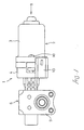
- a motor 2 of the electric motor unit 1 is composed of such members as an armature shaft, an armature core and commutator (not shown) attached to the armature shaft in one united body, a yoke 3 for housing the armature unit, and a brush 5 stowed in a brush holder 4 that will be described later.
- a reduction gear unit 6 is, as conventionally, composed of such members as a worm gear 7 formed as the distal part of the armature shaft, a worm wheel 8 to be engaged with the worm gear 7, and a gear housing 9 for housing the work gear and worm wheel.
- a yoke 3 is shaped like a bottomed cylinder having an opening on one side thereof.
- a cylindrical brush holder 4 is attached to the opening end of the yoke 3.
- Flanges 3a and 4a are formed on the outer circumference of the opening end of the yoke 3 and the outer circumference of the brush holder 4 respectively. The flanges 3a and 4a are met and fixed with screws 10, whereby the brush holder 4 is secured to the yoke 3.
- Brushes 5 are mounted in the distal ends of brush springs 11 that are metallic blade springs.
- the proximal ends of the brush springs 11 are fixed to one ends of lead stays 12 by performing welding or the like so that the brush springs can be electrically connected to the lead stays 12.
- Feeding terminals 14 to be incorporated in a feeding coupler 13 that will be described later are formed as integral parts of the lead stays 12 at the other ends of the lead stays. Power is fed to the brushes 5 through the feeding terminals 14 via the lead stays 12 and brush springs 11.
- the feeding coupler 13 is connected to an external coupler (not shown) of an external power supply in order to feed power to the brushes 5.
- a coupler case 15 that outlines the feeding coupler 13 is formed as an integral part of the brush holder 4 so that the coupler case 15 juts out on the outer circumference of the flange 4a.
- the coupler case 15 is located at a position coincident with a position on the outer circumference of the yoke flange 3a at which an external coupler will not be interfered with the yoke flange 3a when connected.
- the coupler case 15 is shaped like a bottomed cylinder having an opening on a side thereof opposed to the yoke flange 3a.
- a concave groove 4b having an opening on a side thereof opposed to the yoke flange 3a is bored in a region of the brush holder flange 4a leading to the coupler case 15 so that the concave groove 4b can communicate the cylindrical interior of the coupler case 15 with the inner circumferential part of the brush holder 4.
- a brush unit A composed of the brushes 5, brush springs 11, lead stays 12, and feeding terminals 14 is fitted in the brush holder 4 and coupler case 15. At this time, the feeding terminals 14 and the other ends of the lead stays 12 succeeding the feeding terminals are put through the openings of the coupler case 15 and flange concave groove 4b. A retainer 16 that will be described later is put through the opening of the coupler case 15. The feeding terminals 14 can thus be positioned in and supported by the coupler case 15. One ends of the lead stays 12 are fixed to the brush holder 4 by inserting screws 17 into screw holes 12a bored in the brush springs 11 and locking them in screw seats 4c.
- the retainer 16 includes a terminal supporting part 16a to be engaged with the coupler case 15, and a coming-off preventing portion 16b to be engaged with an end of the concave groove 4b on the side of the coupler case 15.
- the bottoms of the terminal supporting part 16a and coming-off preventing portion 16b are formed continuously.
- Stay engagement grooves 16c with which the other ends of the lead stays 12 are engaged are formed over the bottoms.
- Terminal through holes 16d through which the feeding terminals 14 are put and supported are bored in the terminal supporting part 16a so that the terminal through holes communicate with the stay engagement grooves 16c.
- the coming-off preventing portion 16b is formed so that the top of the coming-off preventing portion 16b abuts on the yoke flange 3a in a state in which the retainer 16 is put in the coupler case 15 and concave groove 4b until the retainer 16 abuts on the bottoms thereof, and the brush holder flange 4a and yoke flange 3a are met.
- the coming-off preventing portion 16b is thus sandwiched between the yoke flange 3a and the bottom of the concave groove 4b, and will therefore not come off.
- the feeding terminals 14 are formed as integral parts of the lead stays 12 at the other ends of the lead stays.
- the coupler case 15 is shaped like a bottomed cylinder having an opening on a side thereof opposed to the yoke flange 3a.
- the concave groove 4b having an opening on a side thereof opposed to the yoke flange 3a is bored in the brush holder flange 4a leading to the coupler case 15.
- the feeding terminals 14 and the other ends of the lead stays 12 are put through the openings, and the retainer 16 is then incorporated in order to position and support the feeding terminals 14 and the other ends of the lead stays 12.
- the feeding coupler 13 is thus constructed.
- the retainer 16 is prevented from coming off through the openings because the retainer coming-off preventing portion 16b is sandwiched between the yoke flange 3a and the bottom of the concave groove 4b with the brush holder flange 4a and yoke flange 3a met.
- the brush holder 4 can be molded readily. This contributes to a cost reduction. Furthermore, even when feeding terminals 14 having a different shape that matches any of various external couplers is incorporated, the brush holder 4 can be used in common. Thus, the common use of parts can be attained and a further cost reduction can be achieved.
- the feeding terminals 14 are formed as integral parts of the lead stays 12. Compared with a known structure in which a brush holder is molded using a resin with feeding terminals inserted therein, and the feeding terminals and lead stays are separate parts, the number of parts can be reduced. Furthermore, the work of joining the feeding terminals 14 with the lead stays 12 becomes unnecessary. This results in improved workability and a reduced number of electrical contacts. High reliability can be guaranteed.
- locking claws 12b may be jutted out from the lead stays 12 and press-fitted and secured into the brush holder 4 in order to fix the brush supporting parts of the lead stays 12 to the brush holder 4.
- the retainer 16 is made of a sealing material such as rubber.
- An annular sealing part 16e for sealing the yoke flange 3a and brush holder 4a is formed as an integral part of the retainer 16.
- the yoke and brush holder can be sealed without a dedicated sealing member. This contributes to a reduction in the number of parts.
- there is the merit that incorporation of a seal can be carried out simultaneously with incorporation of a retainer.
Landscapes
- Engineering & Computer Science (AREA)
- Power Engineering (AREA)
- Motor Or Generator Frames (AREA)
- Motor Or Generator Current Collectors (AREA)
Claims (5)
- Eine Versorgungsstruktur in einem elektrischen Motor aufweisend einen Bürstenhalter (4), in dem Bürsten (5) angeordnet sind, und ein Versorgungskopplergehäuse (15), in dem Versorgungsanschlüsse (14) eingepaßt sind, um die Bürsten (5) mit Strom zu versorgen, indem ein externer Koppler verbunden wird, wobei der Bürstenhalter an einem Joch (3) angebracht wird und eine Kantenfläche (4a) hat, die an eine offene Endfläche (3a) des Jochs stößt, und wobei das Versorgungskopplergehäuse (15) integral mit dem Bürstenhalter (4) geformt ist und eine Öffnung hat, die der offenen Endfläche des Jochs (3) gegenüber liegt, wobei die Versorgungsanschlüsse (14) und ein Halter (16) zum Positionieren und Halten der Versorgungsanschlüsse (14) im Versorgungskopplergehäuse (15) in einer Öffnung des Versorgungskopplergehäuses (15) eingepaßt sind, wobei der Halter (16) einen Herausfallschutzabschnitt (16b) aufweist, der zwischen den Bürstenhaltern (4) und dem Joch (3) gehalten wird, um zu verhindern, daß der Halter (16) aus der Öffnung des Versorgungsgehäuses (15) fällt, dadurch gekennzeichnet, daß:
das Versorgungskopplergehäuse (15) wie ein Zylinder mit Boden geformt ist mit einem Schlitz der längs in der Wand gegenüber vom Joch (3) geformt ist, wobei der Herausfallschutzabschnitt (16b) im Schlitz angeordnet ist, um eine im wesentlichen durchgängige Innenwand mit der Wand des Versorgungskopplergehäuses (15) zu bilden. - Versorgungsstruktur in einem elektrischen Motor nach Anspruch 1, dadurch gekennzeichnet, daß eine konkave Nut (4b) auf einer Seite des Bürstenhalters (4) geformt ist, die an das Joch (3) anstößt, so daß sich die konkave Nut (4b) vom Versorgungskopplergehäuse (15) erstreckt und der Herausfallschutzabschnitt (16b) mit der konkaven Nut im Eingriff ist, um ein Herausfallen des Halters (16) aus der Öffnung des Versorgungskopplergehäuses (15) zu verhindern.
- Versorgungsstruktur in einem elektrischen Motor nach Anspruch 1 oder 2 dadurch gekennzeichnet, daß die Versorgungsanschlüsse (14) integral mit Verbindungsankern (12) geformt sind, um die Bürsten (5) zu stützen, und Enden der Verbindungsanker (12), auf deren Seite die Bürste gestützt werden, am Bürstenhalter (4) befestigt sind.
- Versorgungsstruktur in einem elektrischen Motor nach Anspruch 3, dadurch gekennzeichnet, daß Verschlußklauen (12b) herausstehend aus den Verbindungsankern (12) geformt sind und in den Bürstenhalter (4) durch Preßpassung und Sichern eingefügt werden, um die Verbindungsanker (12) am Bürstenhalter (4) zu befestigen.
- Versorgungsstruktur in einem elektrischen Motor nach Anspruch 1, 2, 3 oder 4, dadurch gekennzeichnet, daß ein runder Dichtungsabschnitt (16e) integral mit dem Halter (16) geformt ist, um das offene Ende (3a) des Jochs (3) und die Kantenfläche (4a) des Halters (4) abzudichten.
Applications Claiming Priority (3)
| Application Number | Priority Date | Filing Date | Title |
|---|---|---|---|
| JP22172196 | 1996-08-05 | ||
| JP221721/96 | 1996-08-05 | ||
| JP22172196A JP3274072B2 (ja) | 1996-08-05 | 1996-08-05 | 電動モータにおける給電部構造 |
Publications (2)
| Publication Number | Publication Date |
|---|---|
| EP0823768A1 EP0823768A1 (de) | 1998-02-11 |
| EP0823768B1 true EP0823768B1 (de) | 2001-10-24 |
Family
ID=16771226
Family Applications (1)
| Application Number | Title | Priority Date | Filing Date |
|---|---|---|---|
| EP97401831A Expired - Lifetime EP0823768B1 (de) | 1996-08-05 | 1997-07-31 | Struktur zum Versorgen eines elektrischen Motors |
Country Status (5)
| Country | Link |
|---|---|
| US (1) | US5886448A (de) |
| EP (1) | EP0823768B1 (de) |
| JP (1) | JP3274072B2 (de) |
| CA (1) | CA2211917C (de) |
| DE (1) | DE69707604T2 (de) |
Cited By (2)
| Publication number | Priority date | Publication date | Assignee | Title |
|---|---|---|---|---|
| DE10342222A1 (de) * | 2003-09-11 | 2005-05-04 | K Tec Kunststoffverarbeitung G | Topf- oder becherförmiger Träger |
| DE10342221B4 (de) * | 2003-09-11 | 2008-05-08 | K-Tec Kunststoffverarbeitung Gmbh | Anordnung zur elektrischen Versorgung eines Motors |
Families Citing this family (15)
| Publication number | Priority date | Publication date | Assignee | Title |
|---|---|---|---|---|
| DE19642132A1 (de) * | 1996-10-12 | 1998-04-16 | Bosch Gmbh Robert | Elektromotor |
| DE10003901B4 (de) * | 2000-01-29 | 2004-02-05 | Schunk Metall Und Kunststoff Gmbh | Tragplatte für zumindest eine Kohlebürste |
| US6548934B1 (en) * | 2000-07-31 | 2003-04-15 | Valeo Electrical Systems, Inc. | Brush holder lead frame with integral electrical terminals |
| DE10148705A1 (de) * | 2001-10-02 | 2003-04-10 | Valeo Auto Electric Gmbh | Bürstenhaltesystem und Antriebseinrichtung |
| JP4490030B2 (ja) * | 2002-07-18 | 2010-06-23 | 株式会社ミツバ | 電動モータ |
| US6756619B2 (en) * | 2002-08-26 | 2004-06-29 | Micron Technology, Inc. | Semiconductor constructions |
| DE10342219A1 (de) | 2003-09-11 | 2005-04-21 | K Tec Kunststoffverarbeitung G | Topf- oder becherförmiger Träger |
| WO2005077017A2 (en) * | 2004-02-06 | 2005-08-25 | Motor Products Corporation | Improved brush card apparatus and method |
| US6949861B1 (en) * | 2004-04-13 | 2005-09-27 | Su-Chen Liao | Carbon brush holder |
| JP5118548B2 (ja) * | 2007-05-14 | 2013-01-16 | アスモ株式会社 | モータ |
| JP5682301B2 (ja) * | 2010-12-24 | 2015-03-11 | アイシン精機株式会社 | 回転電機の製造方法 |
| FR2976411B1 (fr) * | 2011-06-08 | 2016-05-06 | Valeo Systemes Dessuyage | Assemblage support charbon |
| FR2976538B1 (fr) | 2011-06-17 | 2013-07-26 | Valeo Systemes Dessuyage | Support de connecteurs et dispositif de distribution de liquide lave-glace pour balais d'essuie-glace de vehicule automobile |
| JP5792530B2 (ja) * | 2011-06-30 | 2015-10-14 | アスモ株式会社 | モータ |
| JP5959499B2 (ja) | 2013-12-27 | 2016-08-02 | マブチモーター株式会社 | モータ |
Family Cites Families (15)
| Publication number | Priority date | Publication date | Assignee | Title |
|---|---|---|---|---|
| US4041339A (en) * | 1975-11-10 | 1977-08-09 | General Motors Corporation | Dynamoelectric machine with brush holding structure |
| FR2530885A1 (fr) * | 1982-07-22 | 1984-01-27 | Marchal Equip Auto | Sous-ensemble d'alimentation pour moteur electrique, et moteur comprenant un tel sous-ensemble |
| FR2571553B1 (fr) * | 1984-10-09 | 1987-10-23 | Marchal Equip Auto | Porte-balai pour machine electrique, et machine electrique equipee d'un tel porte-balai |
| DE8527874U1 (de) * | 1985-09-30 | 1986-08-07 | Siemens AG, 1000 Berlin und 8000 München | Kommutatormotor in geschlossener Bauart |
| DE3810961A1 (de) * | 1988-03-31 | 1989-10-19 | Schunk Motorensysteme | Becherfoermiger traeger bestimmt fuer einen elektromotor |
| DE3810963C2 (de) * | 1988-03-31 | 1995-11-23 | Schunk Motorensysteme | Gitter aus elektrisch leitendem Blechmaterial sowie Verfahren zur Herstellung eines Gitters |
| JPH0649084Y2 (ja) * | 1989-03-14 | 1994-12-12 | 自動車電機工業株式会社 | 小型モータの電源接続構造 |
| ES2054370T3 (es) * | 1989-08-25 | 1994-08-01 | Siemens Ag | Motor electrico del tipo de construccion cerrado. |
| US5231321A (en) * | 1989-08-28 | 1993-07-27 | Asmo Co., Ltd. | Noise preventing arrangement of a motor |
| JPH0649100Y2 (ja) * | 1989-12-04 | 1994-12-12 | 株式会社三ツ葉電機製作所 | 直流機の配線装置 |
| DE59005643D1 (de) * | 1990-08-17 | 1994-06-09 | Siemens Ag | Elektromotor, insbesondere feuchtigkeitsdicht geschlossener Kommutatormotor zum Antrieb einer axial angeflanschten Hydraulik-Pumpe. |
| US5444315A (en) * | 1992-12-18 | 1995-08-22 | Siemens Aktiengesellschaft | Bushing isolator for lead-through of electrical lines providing moisture sealing between two housings |
| EP0618659B2 (de) * | 1993-03-31 | 2001-07-04 | Siemens Aktiengesellschaft | Kommutatormotor-Getriebe-Antriebseinheit, insbesondere Kraftfahrzeug-Fensterheberantrieb |
| US5440186A (en) * | 1993-09-13 | 1995-08-08 | United Technologies Automotive, Inc. | Motor with isolated brush card assembly |
| DE19517667A1 (de) * | 1995-05-13 | 1996-11-14 | Vdo Schindling | Gleichstrommaschine |
-
1996
- 1996-08-05 JP JP22172196A patent/JP3274072B2/ja not_active Expired - Lifetime
-
1997
- 1997-07-29 CA CA002211917A patent/CA2211917C/en not_active Expired - Fee Related
- 1997-07-31 EP EP97401831A patent/EP0823768B1/de not_active Expired - Lifetime
- 1997-07-31 DE DE69707604T patent/DE69707604T2/de not_active Expired - Fee Related
- 1997-08-04 US US08/905,742 patent/US5886448A/en not_active Expired - Fee Related
Cited By (2)
| Publication number | Priority date | Publication date | Assignee | Title |
|---|---|---|---|---|
| DE10342222A1 (de) * | 2003-09-11 | 2005-05-04 | K Tec Kunststoffverarbeitung G | Topf- oder becherförmiger Träger |
| DE10342221B4 (de) * | 2003-09-11 | 2008-05-08 | K-Tec Kunststoffverarbeitung Gmbh | Anordnung zur elektrischen Versorgung eines Motors |
Also Published As
| Publication number | Publication date |
|---|---|
| CA2211917A1 (en) | 1998-02-05 |
| EP0823768A1 (de) | 1998-02-11 |
| DE69707604T2 (de) | 2002-09-05 |
| DE69707604D1 (de) | 2001-11-29 |
| US5886448A (en) | 1999-03-23 |
| CA2211917C (en) | 2003-04-22 |
| JPH1051993A (ja) | 1998-02-20 |
| JP3274072B2 (ja) | 2002-04-15 |
Similar Documents
| Publication | Publication Date | Title |
|---|---|---|
| EP0823768B1 (de) | Struktur zum Versorgen eines elektrischen Motors | |
| US8342880B2 (en) | Electrical connector with elastically held terminals | |
| CN100407507C (zh) | 防水接头 | |
| JP4650691B2 (ja) | 電気接続構造 | |
| US6955567B2 (en) | Junction terminal and connector having the same | |
| US6814581B2 (en) | Connector for towing vehicle and method of manufacturing same | |
| EP0520503B1 (de) | Bürstenlose Vorrichtung zur Übertragung elektrischer Signale | |
| US20100041268A1 (en) | Electrical Equipment | |
| EP1128472A1 (de) | Abgeschirmter Verbinder | |
| US6537105B2 (en) | Electrical connection box | |
| JP3859972B2 (ja) | 機器のシールドケースへの電線接続構造 | |
| EP0928900B2 (de) | Elektrische Lüftereinheit für Kraftfahrzeugklimaanlage | |
| JPH09161893A (ja) | コネクタの接続構造 | |
| US20020121019A1 (en) | Method of assembling starter lead wire | |
| JP2000127934A (ja) | アンチロックブレーキ装置の液圧ユニット | |
| JP2001297845A (ja) | ケーブルリール | |
| JP3869139B2 (ja) | 電気接続箱 | |
| JP4602264B2 (ja) | シールドコネクタ | |
| US20250364738A1 (en) | Terminal Connection Structure | |
| US6958558B2 (en) | Electric motor in particular for a steering system in a vehicle | |
| US20250364737A1 (en) | Terminal Connection Structure | |
| JP7512992B2 (ja) | コネクタ | |
| JP7810673B2 (ja) | コネクタおよびワイヤハーネス | |
| JP7744107B2 (ja) | 端子台 | |
| JP3356117B2 (ja) | 電気接続箱 |
Legal Events
| Date | Code | Title | Description |
|---|---|---|---|
| PUAI | Public reference made under article 153(3) epc to a published international application that has entered the european phase |
Free format text: ORIGINAL CODE: 0009012 |
|
| AK | Designated contracting states |
Kind code of ref document: A1 Designated state(s): DE FR IT |
|
| AX | Request for extension of the european patent |
Free format text: AL;LT;LV;RO;SI |
|
| 17P | Request for examination filed |
Effective date: 19980806 |
|
| AKX | Designation fees paid |
Free format text: DE FR IT |
|
| RBV | Designated contracting states (corrected) |
Designated state(s): DE FR IT |
|
| 17Q | First examination report despatched |
Effective date: 19991118 |
|
| GRAG | Despatch of communication of intention to grant |
Free format text: ORIGINAL CODE: EPIDOS AGRA |
|
| GRAG | Despatch of communication of intention to grant |
Free format text: ORIGINAL CODE: EPIDOS AGRA |
|
| GRAH | Despatch of communication of intention to grant a patent |
Free format text: ORIGINAL CODE: EPIDOS IGRA |
|
| GRAH | Despatch of communication of intention to grant a patent |
Free format text: ORIGINAL CODE: EPIDOS IGRA |
|
| RAP1 | Party data changed (applicant data changed or rights of an application transferred) |
Owner name: MITSUBA CORPORATION |
|
| GRAA | (expected) grant |
Free format text: ORIGINAL CODE: 0009210 |
|
| AK | Designated contracting states |
Kind code of ref document: B1 Designated state(s): DE FR IT |
|
| REF | Corresponds to: |
Ref document number: 69707604 Country of ref document: DE Date of ref document: 20011129 |
|
| ET | Fr: translation filed | ||
| PLBE | No opposition filed within time limit |
Free format text: ORIGINAL CODE: 0009261 |
|
| STAA | Information on the status of an ep patent application or granted ep patent |
Free format text: STATUS: NO OPPOSITION FILED WITHIN TIME LIMIT |
|
| 26N | No opposition filed | ||
| PGFP | Annual fee paid to national office [announced via postgrant information from national office to epo] |
Ref country code: DE Payment date: 20080814 Year of fee payment: 12 |
|
| PGFP | Annual fee paid to national office [announced via postgrant information from national office to epo] |
Ref country code: IT Payment date: 20080728 Year of fee payment: 12 Ref country code: FR Payment date: 20080718 Year of fee payment: 12 |
|
| REG | Reference to a national code |
Ref country code: FR Ref legal event code: ST Effective date: 20100331 |
|
| PG25 | Lapsed in a contracting state [announced via postgrant information from national office to epo] |
Ref country code: FR Free format text: LAPSE BECAUSE OF NON-PAYMENT OF DUE FEES Effective date: 20090731 |
|
| PG25 | Lapsed in a contracting state [announced via postgrant information from national office to epo] |
Ref country code: DE Free format text: LAPSE BECAUSE OF NON-PAYMENT OF DUE FEES Effective date: 20100202 |
|
| PG25 | Lapsed in a contracting state [announced via postgrant information from national office to epo] |
Ref country code: IT Free format text: LAPSE BECAUSE OF NON-PAYMENT OF DUE FEES Effective date: 20090731 |