EP0824062B1 - Article multicouche ayant une couche de surface efficacement liée et procédé pour sa fabrication - Google Patents
Article multicouche ayant une couche de surface efficacement liée et procédé pour sa fabrication Download PDFInfo
- Publication number
- EP0824062B1 EP0824062B1 EP97304233A EP97304233A EP0824062B1 EP 0824062 B1 EP0824062 B1 EP 0824062B1 EP 97304233 A EP97304233 A EP 97304233A EP 97304233 A EP97304233 A EP 97304233A EP 0824062 B1 EP0824062 B1 EP 0824062B1
- Authority
- EP
- European Patent Office
- Prior art keywords
- substratum
- intermediary
- surface application
- application material
- plastic member
- Prior art date
- Legal status (The legal status is an assumption and is not a legal conclusion. Google has not performed a legal analysis and makes no representation as to the accuracy of the status listed.)
- Expired - Lifetime
Links
Images

Classifications
-
- B—PERFORMING OPERATIONS; TRANSPORTING
- B29—WORKING OF PLASTICS; WORKING OF SUBSTANCES IN A PLASTIC STATE IN GENERAL
- B29C—SHAPING OR JOINING OF PLASTICS; SHAPING OF MATERIAL IN A PLASTIC STATE, NOT OTHERWISE PROVIDED FOR; AFTER-TREATMENT OF THE SHAPED PRODUCTS, e.g. REPAIRING
- B29C45/00—Injection moulding, i.e. forcing the required volume of moulding material through a nozzle into a closed mould; Apparatus therefor
- B29C45/16—Making multilayered or multicoloured articles
-
- B—PERFORMING OPERATIONS; TRANSPORTING
- B29—WORKING OF PLASTICS; WORKING OF SUBSTANCES IN A PLASTIC STATE IN GENERAL
- B29C—SHAPING OR JOINING OF PLASTICS; SHAPING OF MATERIAL IN A PLASTIC STATE, NOT OTHERWISE PROVIDED FOR; AFTER-TREATMENT OF THE SHAPED PRODUCTS, e.g. REPAIRING
- B29C70/00—Shaping composites, i.e. plastics material comprising reinforcements, fillers or preformed parts, e.g. inserts
- B29C70/68—Shaping composites, i.e. plastics material comprising reinforcements, fillers or preformed parts, e.g. inserts by incorporating or moulding on preformed parts, e.g. inserts or layers, e.g. foam blocks
- B29C70/78—Moulding material on one side only of the preformed part
-
- B—PERFORMING OPERATIONS; TRANSPORTING
- B32—LAYERED PRODUCTS
- B32B—LAYERED PRODUCTS, i.e. PRODUCTS BUILT-UP OF STRATA OF FLAT OR NON-FLAT, e.g. CELLULAR OR HONEYCOMB, FORM
- B32B27/00—Layered products comprising a layer of synthetic resin
- B32B27/12—Layered products comprising a layer of synthetic resin next to a fibrous or filamentary layer
-
- B—PERFORMING OPERATIONS; TRANSPORTING
- B32—LAYERED PRODUCTS
- B32B—LAYERED PRODUCTS, i.e. PRODUCTS BUILT-UP OF STRATA OF FLAT OR NON-FLAT, e.g. CELLULAR OR HONEYCOMB, FORM
- B32B5/00—Layered products characterised by the non- homogeneity or physical structure, i.e. comprising a fibrous, filamentary, particulate or foam layer; Layered products characterised by having a layer differing constitutionally or physically in different parts
- B32B5/02—Layered products characterised by the non- homogeneity or physical structure, i.e. comprising a fibrous, filamentary, particulate or foam layer; Layered products characterised by having a layer differing constitutionally or physically in different parts characterised by structural features of a fibrous or filamentary layer
- B32B5/024—Woven fabric
-
- B—PERFORMING OPERATIONS; TRANSPORTING
- B32—LAYERED PRODUCTS
- B32B—LAYERED PRODUCTS, i.e. PRODUCTS BUILT-UP OF STRATA OF FLAT OR NON-FLAT, e.g. CELLULAR OR HONEYCOMB, FORM
- B32B5/00—Layered products characterised by the non- homogeneity or physical structure, i.e. comprising a fibrous, filamentary, particulate or foam layer; Layered products characterised by having a layer differing constitutionally or physically in different parts
- B32B5/02—Layered products characterised by the non- homogeneity or physical structure, i.e. comprising a fibrous, filamentary, particulate or foam layer; Layered products characterised by having a layer differing constitutionally or physically in different parts characterised by structural features of a fibrous or filamentary layer
- B32B5/06—Layered products characterised by the non- homogeneity or physical structure, i.e. comprising a fibrous, filamentary, particulate or foam layer; Layered products characterised by having a layer differing constitutionally or physically in different parts characterised by structural features of a fibrous or filamentary layer characterised by a fibrous or filamentary layer mechanically connected, e.g. by needling to another layer, e.g. of fibres, of paper
-
- E—FIXED CONSTRUCTIONS
- E04—BUILDING
- E04C—STRUCTURAL ELEMENTS; BUILDING MATERIALS
- E04C2/00—Building elements of relatively thin form for the construction of parts of buildings, e.g. sheet materials, slabs, or panels
- E04C2/02—Building elements of relatively thin form for the construction of parts of buildings, e.g. sheet materials, slabs, or panels characterised by specified materials
- E04C2/26—Building elements of relatively thin form for the construction of parts of buildings, e.g. sheet materials, slabs, or panels characterised by specified materials composed of materials covered by two or more of groups E04C2/04, E04C2/08, E04C2/10 or of materials covered by one of these groups with a material not specified in one of the groups
-
- Y—GENERAL TAGGING OF NEW TECHNOLOGICAL DEVELOPMENTS; GENERAL TAGGING OF CROSS-SECTIONAL TECHNOLOGIES SPANNING OVER SEVERAL SECTIONS OF THE IPC; TECHNICAL SUBJECTS COVERED BY FORMER USPC CROSS-REFERENCE ART COLLECTIONS [XRACs] AND DIGESTS
- Y10—TECHNICAL SUBJECTS COVERED BY FORMER USPC
- Y10T—TECHNICAL SUBJECTS COVERED BY FORMER US CLASSIFICATION
- Y10T442/00—Fabric [woven, knitted, or nonwoven textile or cloth, etc.]
- Y10T442/10—Scrim [e.g., open net or mesh, gauze, loose or open weave or knit, etc.]
- Y10T442/102—Woven scrim
- Y10T442/171—Including a layer derived from a water-settable material [e.g., cement, gypsum, etc.]
-
- Y—GENERAL TAGGING OF NEW TECHNOLOGICAL DEVELOPMENTS; GENERAL TAGGING OF CROSS-SECTIONAL TECHNOLOGIES SPANNING OVER SEVERAL SECTIONS OF THE IPC; TECHNICAL SUBJECTS COVERED BY FORMER USPC CROSS-REFERENCE ART COLLECTIONS [XRACs] AND DIGESTS
- Y10—TECHNICAL SUBJECTS COVERED BY FORMER USPC
- Y10T—TECHNICAL SUBJECTS COVERED BY FORMER US CLASSIFICATION
- Y10T442/00—Fabric [woven, knitted, or nonwoven textile or cloth, etc.]
- Y10T442/10—Scrim [e.g., open net or mesh, gauze, loose or open weave or knit, etc.]
- Y10T442/102—Woven scrim
- Y10T442/172—Coated or impregnated
- Y10T442/176—Three or more layers
Definitions
- the invention relates generally to a multiple-layer article having a surface application material effectively bonded to a plastic member and a method of effectively bonding a surface application material to a plastic member, and more particularly to a multiple-layer article and a method of making same wherein an intermediary substratum is located between a plastic member and a hardened surface application material so that the hardened surface application material is effectively bonded to the plastic member.
- drywall, concrete slabs, plywood and other such materials are used as building components.
- a building component such as, for example, a wall of a building, must be able to bear a required load, insulate adequately, and resist moisture effectively.
- a building component typically must be either aesthetically pleasing to the eye, or at least must be capable of being modified so that it is aesthetically pleasing to the eye.
- a plastic sheet which is strong, insulating, moisture resistant and weldable by utilizing, for example, the method for molding a plastic article of varied density as described in United States Patent No. 5,437,823.
- adding a surface application material such as stucco, plaster, ceramic, cement, or concrete to a plastic sheet can often further endow the plastic sheet with certain qualities, or can at least enhance certain qualities of the plastic sheet.
- some types of surface application materials can protect the plastic sheet from bacteria, rot, or even ultra-violet light.
- surface application materials can often make the plastic sheet more flame resistant or can improve the overall aesthetic appearance of the plastic sheet. Therefore, applying a surface application material to a plastic sheet would be desirable in many circumstances.
- Another advantage of the present invention is to provide a multiple-layer article having a surface application material effectively bonded to a plastic member.
- a further advantage of the present invention is to provide a multiple-layer article having an intermediary substratum so that a surface application material is effectively bonded to a plastic member.
- Still another advantage of the present invention is to provide a plastic member which is not only load bearing, weldable, moisture resistant, and insulating, but can be enhanced with a surface application material in an economically feasible fashion.
- Yet another advantage of the present invention is to provide a multiple-layer article having a surface application material effectively bonded to a plastic member where the surface application material does not crack or break away from the plastic member due to the difference between the rate of expansion of the plastic member and the rate of expansion of the surface application material.
- Still a further advantage of the present invention is to provide a multiple-layer article which includes a relatively thin coating of surface application material which will remain effectively bonded to a plastic member.
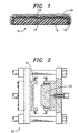
- FIG. 1 Shown in FIG. 1 is a multiple-layer article 10 including a plastic member 12 comprised of ethylene. While the present invention is, in fact, particularly useful when the plastic member 12 is comprised of ethylene, the plastic member 12 may instead be comprised of essentially any type of plastic. Regardless of which type of plastic is used in order to provide the plastic member 12, preferably the plastic member 12 is strong, insulating, moisture resistant and weldable so that the plastic member 12 is ideal when used as a building component such as a wall. As shown, the plastic member 12 is partially absorbed into and bonded to a first side 16 of an intermediary substratum 14. Preferably, the intermediary substratum 14 is a fabric such as woven fabric, needle-punched fabric, or a heavy spun fabric.
- the intermediary substratum 14 is a fabric such as woven fabric, needle-punched fabric, or a heavy spun fabric.
- the intermediary substratum 14 may be another type of fabric or may even be a non-fabric such as metal.
- a hardened surface application material 20 is partially absorbed into and bonded to a second side 18 of the intermediary substratum 14.
- the hardened surface application material 20 is stucco; however, the hardened surface application material 20 may be plaster, ceramic, cement, concrete or any other hardened surface material.
- the hardened surface material 20 further endows the plastic member 12 and therefore, the multiple-layer article 10 as a whole, with additional qualities, or at least enhances certain qualities of the plastic member 12 so that the multiple-layer article 10 becomes even more ideal for use as a building component.
- some types of surface application materials can protect plastic from bacteria, rot, or ultra-violet light. Additionally, the surface application material may make plastic more flame resistant or may improve the overall aesthetic appearance of the plastic member.
- the multiple-layer article 10 in FIG. 1 includes an intermediary substratum 14 between the plastic member 12 and the surface application material 20.
- the plastic member 12 is partially absorbed into and bonded to the first side 16 of the intermediary substratum 14, and the hardened surface application material 20 is partially absorbed into and bonded to the second side 18 of the intermediary substratum 14.
- the intermediary substratum 14 allows the surface application material 20 to be effectively bonded to the plastic member 12. While the rate of expansion of the plastic member 12 in response to, for example, heat, is typically dramatically different from the rate of expansion of the surface application material 20, the intermediary substratum 14 essentially accommodates this difference.
- the surface application material 20 does not crack or break away from the plastic member 12 even though the multiple-layer article 10 may be subjected to heat. Additionally, the surface application material 20 need not be very thick in order to remain bonded to the intermediary substratum 14, and therefore effectively bonded to the plastic member 12.
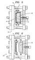
- a mold unit 22 may be provided where the mold unit 22 has a first mold section 24 and a second mold section 26. As shown in FIG. 4, the first mold section 24 and the second mold section 26 form a mold cavity 28 upon being clamped together. However, before clamping together the first mold section 24 and the second mold section 26 to form the mold cavity 28, preferably the intermediary substratum 14 is secured across the first mold section 24 so that the first side 16 of the intermediary substratum 14 faces the second mold section 26 as shown in FIG. 3. As mentioned, preferably the intermediary substratum 14 is a fabric such as woven fabric, needle-punched fabric, or a heavy spun fabric.
- the intermediary substratum 14 is secured across the first mold section 24 as shown in FIG. 3, the first mold section 24 is clamped together with the second mold section 26 to form the mold cavity 28 therebetween as shown in FIG. 4.
- the intermediary substratum 14 extends across the mold cavity 28.
- the intermediary substratum 14 may be secured across the second mold section 26 instead of the first mold section 24.
- a plastic injection material 30 such as an ethylene-based plastic injection material 30 is injected into the mold cavity 28.
- the plastic injection material 30 contacts and becomes partially absorbed into the first side 16 of the intermediary substratum 14.
- the plastic injection material 30 is allowed to at least partially cool in the mold cavity 28 to form the plastic member 12, and the cooling of the plastic injection material 30 provides a bonding relationship between the first side 16 of the intermediary substratum 14 and the plastic member 12.
- the mold cavity 28 is opened by moving apart the first mold section 24 and the second mold section 26 as shown in FIG. 6.
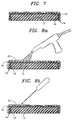
- the plastic member 12 and intermediary substratum 14 are removed from the mold unit 22, and the plastic member 12 and intermediary substratum 14 appear as shown in FIG. 7.
- the surface application material 20 is applied onto the second side 18 of the intermediary substratum 14.
- the surface application material 20 is stucco and is applied by spraying it onto the second side 18 of the intermediary substratum 14 as shown in FIG. 8a.
- the surface application material 20 can be hand troweled onto the second side 18 of the intermediary substratum 14 as shown in FIG. 8b, or a combination of spraying and hand troweling can be utilized.
- the surface application material 20 becomes partially absorbed into the second side 18 of the intermediary substratum 14.
- the hardening provides a bonding relationship between the surface application material 20 and the second side 18 of the intermediary substratum 14 to provide the multiple-layer article 10 as shown in FIG. 1.
- the multiple-layer article 10 can be initially provided without the surface application material 20, and the surface application material 20 can be added at the construction site.
- a plastic member 12 bonded to an intermediary substratum 14, such as is shown in FIG. 7 be supplied to a construction worker at a construction site. While at the construction site, the construction worker can apply the desired surface application material 20 to the intermediary substratum 14 in order to provide the resulting multiple-layer article 10 as shown in FIG. 1 which is then ideal to use as a building component.
- the multiple-layer article 10 in FIG. 1 includes an intermediary substratum 14 between the plastic member 12 and the surface application material 20.
- the plastic member 12 is partially absorbed into and bonded to the first side 16 of the intermediary substratum 14, and the hardened surface application material 20 is partially absorbed into and bonded to the second side 18 of the intermediary substratum 14.
- the intermediary substratum 14 allows the surface application material 20 to be effectively bonded to the plastic member 12. While the rate of expansion of the plastic member 12 is typically quite different from the rate of expansion of the surface application material 20, the intermediary substratum 14 essentially accommodates this difference.
- the surface application material 20 does not crack or break away from the plastic member 12 even though the multiple-layer article 10 may be subjected to heat such that the plastic member 12 expands. Additionally, the intermediary substratum 14 allows the surface application material 20 to be thinly applied, yet remain bonded to the intermediary substratum 14 when the plastic member 12 expands.
Landscapes
- Engineering & Computer Science (AREA)
- Architecture (AREA)
- Mechanical Engineering (AREA)
- Structural Engineering (AREA)
- Composite Materials (AREA)
- Civil Engineering (AREA)
- Chemical & Material Sciences (AREA)
- Manufacturing & Machinery (AREA)
- Textile Engineering (AREA)
- Laminated Bodies (AREA)
- Injection Moulding Of Plastics Or The Like (AREA)
- Moulds For Moulding Plastics Or The Like (AREA)
- Finishing Walls (AREA)
Claims (21)
- Procédé pour coller efficacement un matériau d'application de surface (20) sur un élément en matière plastique moulé par injection (12), ledit procédé comprenant les opérations suivantes :a) on procure une unité de moulage (22) ayant une première partie de moule (24) et une deuxième partie de moule (26), ladite première partie de moule (24) et ladite deuxième partie de moule (26) formant une cavité de moule (28) lorsqu'elles sont serrées ensemble ;b) on serre ladite première partie de moule (24) et ladite deuxième partie de moule (26) ensemble en formant ainsi ladite cavité de moule (28) entre elles ;c) on place au moins une partie d'un substrat intermédiaire (14) à l'intérieur de ladite cavité de moule (28), ledit substrat intermédiaire (14) ayant un premier côté (16) et un deuxième côté (18) ;d) on injecte un matériau d'injection en matière plastique (30) dans ladite cavité de moule (28), ledit matériau d'injection en matière plastique (30) venant contact avec, et devenant partiellement absorbé dans, au moins une partie dudit premier côté (16) dudit substrat intermédiaire (14) lorsque ledit matériau d'injection (30) est injecté dans ladite cavité de moule (28) ;e) on permet audit matériau d'injection (30) de se refroidir au moins partiellement dans ladite cavité de moule (28) pour former ledit élément en matière plastique (12), ledit refroidissement dudit matériau d'injection (30) réalisant une relation de collage entre ledit premier côté (16) dudit substrat intermédiaire (14) et ledit élément en matière plastique (12) ;f) on enlève ledit élément en matière plastique (12) et ledit substrat intermédiaire (14) collé sur ledit élément en matière plastique (12) depuis ladite cavité de moule (28) ;g) on applique ledit matériau d'application de surface (20) sur au moins une partie dudit deuxième côté (18) dudit substrat intermédiaire (14), ledit matériau d'application de surface (20) devenant partiellement absorbé dans ladite partie dudit deuxième côté (18) dudit substrat intermédiaire (14) ; eth) on permet audit matériau d'application de surface (20) de durcir au cours du temps, ledit durcissement dudit matériau d'application de surface (20) au cours du temps réalisant ainsi une relation de collage entre ledit matériau d'application de surface (20) et ledit deuxième côté (16) dudit substrat intermédiaire (14).
- Procédé selon la revendication 1, dans lequel ledit élément en matière plastique (12) présente un premier coefficient de dilatation, et ledit matériau d'application de surface (20) présente un deuxième coefficient de dilatation différent dudit premier coefficient de dilatation, et dans lequel, lors du durcissement dudit matériau d'application de surface (20), ledit substrat intermédiaire (14) stabilise ledit matériau d'application de surface (20) en conciliant ledit premier coefficient de dilatation et ledit deuxième coefficient de dilatation.
- Procédé selon l'une ou l'autre des revendications 1 et 2, dans lequel ledit matériau d'application de surface (20) est un matériau d'application de surface (20) choisi parmi le groupe comprenant le stuc, plâtre, céramique, ciment et béton.
- Procédé selon l'une quelconque des revendications précédentes, dans lequel ladite matière plastique (30) comprend de l'éthylène.
- Procédé selon l'une quelconque des revendications précédentes, dans lequel ledit substrat intermédiaire (14) comprend un tissu tissé.
- Procédé selon l'une quelconque des revendications 1 à 4, dans lequel ledit substrat intermédiaire (14) comprend un tissu poinçonné avec des aiguilles.
- Procédé selon l'une quelconque des revendications 1 à 5, dans lequel ledit substrat intermédiaire (14) comprend un tissu filé lourd.
- Procédé selon l'une quelconque des revendications précédentes, dans lequel l'opération d'application dudit matériau d'application de surface (20) comprend la pulvérisation dudit matériau d'application de surface (20) sur ledit substrat intermédiaire (14).
- Procédé selon l'une quelconque des revendications 1 à 7, dans lequel l'opération d'application dudit matériau d'application de surface (20) comprend l'application manuelle à la truelle dudit matériau d'application de surface (20) sur ledit substrat intermédiaire (14).
- Procédé selon l'une quelconque des revendications précédentes, dans lequel l'opération d'application dudit matériau d'application de surface (20) comprend la pulvérisation et l'application manuelle à la truelle dudit matériau d'application de surface (20) sur ledit substrat intermédiaire (14).
- Article multicouches (10) comprenant :a) un élément en matière plastique (12) ;b) un substrat intermédiaire (14) ayant un premier côté (16) et un deuxième côté (18), une partie dudit élément en matière plastique (12) étant partiellement absorbée dans au moins une partie dudit premier côté (16) dudit substrat intermédiaire (14), ladite partie dudit premier côté (16) dudit substrat intermédiaire (14) étant en relation de collage avec ladite partie dudit élément en matière plastique (12) ; etc) un matériau d'application de surface (20) durci et partiellement absorbé dans au moins une partie dudit deuxième côté (18) dudit substrat intermédiaire (14), ledit matériau d'application de surface (20) durci étant en relation de collage avec ladite partie dudit deuxième côté (18) dudit substrat intermédiaire (14).
- Article multicouches (10) selon la revendication 11, dans lequel ledit élément en matière plastique (12) présente un premier coefficient de dilatation et ledit matériau d'application de surface (20) présente un deuxième coefficient de dilatation différent dudit premier coefficient de dilatation, et dans lequel lors du durcissement dudit matériau d'application de surface (20) ledit substrat intermédiaire (14) stabilise ledit matériau d'application de surface (20) en conciliant à la fois ledit premier coefficient de dilatation et ledit deuxième coefficient de dilatation.
- Article multicouches (10) selon l'une ou l'autre des revendications 11 et 12, dans lequel ledit matériau d'application de surface (20) durci est un matériau d'application de surface (20) durci choisi parmi le groupe comprenant le stuc, plâtre, céramique, ciment et béton.
- Article multicouches (10) selon l'une quelconque des revendications 11 à 13, dans lequel ledit élément en matière plastique (12) comprend de l'éthylène.
- Article multicouches (10) selon l'une quelconque des revendications 11 à 14, dans lequel ledit substrat intermédiaire (14) comprend un tissu tissé.
- Article multicouches (10) selon l'une quelconque des revendications 11 à 14, dans lequel ledit substrat intermédiaire (14) comprend un tissu poinçonné avec des aiguilles.
- Article multicouches (10) selon l'une quelconque des revendications 11 à 15, dans lequel ledit substrat intermédiaire (14) comprend un tissu filé lourd.
- Article multicouches (10) selon l'une quelconque des revendications 11 à 17, dans lequel ledit matériau d'application de surface (20) a été appliqué par pulvérisation dudit matériau d'application de surface (20) sur ledit substrat intermédiaire (14).
- Article multicouches (10) selon l'une quelconque des revendications 11 à 18, dans lequel ledit matériau d'application de surface (20) durci a été appliqué par application manuelle à la truelle dudit matériau d'application de surface (20) sur ledit substrat intermédiaire (14).
- Article multicouches (10) selon l'une quelconque des revendications 11 à 19, dans lequel ledit matériau d'application de surface (20) durci a été appliqué par pulvérisation et par application manuelle à la truelle dudit matériau d'application de surface (20) sur ledit substrat intermédiaire (14).
- Procédé pour coller efficacement un matériau en stuc (20) sur un élément en matière plastique (12) moulé par injection, ledit procédé comprenant les opérations suivantes :a) on procure une unité de moule (22) ayant une première partie de moule (24) et une deuxième partie de moule (26), ladite première partie de moule (24) et ladite deuxième partie de moule (26) formant une cavité de moule (28) lorsqu'elles sont serrées ensemble ;b) on procure un substrat intermédiaire en tissu (14) ayant un premier côté (16) et un deuxième côté (18) ;c) on fixe ledit substrat intermédiaire en tissu (14) à travers ladite première partie de moule (24) de sorte que ledit premier côté (16) dudit substrat intermédiaire en tissu (14) fait face vers ladite deuxième partie de moule (26) ;d) on serre ladite première partie de moule (24) et ladite deuxième partie de moule (26) ensemble, en formant ainsi ladite cavité de moule (28) entre elles, ledit serrage ayant pour résultat qu'au moins une partie dudit substrat intermédiaire en tissu (14) s'étend à travers ladite cavité de moule (28) ;e) on injecte un matériau d'injection en matière plastique à base d'éthylène (30) dans ladite cavité de moule (28), ledit matériau d'injection (30) venant en contact avec, et devenant partiellement absorbé dans, au moins une partie dudit premier côté (16) dudit substrat intermédiaire en tissu (14) lorsque ledit matériau d'injection (30) est injecté dans ladite cavité de moule (28) ;f) on permet audit matériau d'injection (30) de se refroidir au moins partiellement dans ladite cavité de moule (28) pour former ledit élément en matière plastique moulé par injection (12), ledit refroidissement dudit matériau d'injection (30) réalisant une relation de collage entre ledit premier côté (16) dudit substrat intermédiaire en tissu (14) et dudit élément en matière plastique moulé par injection (12);g) on enlève ledit élément en matière plastique moulé par injection (12) et ledit substrat intermédiaire en tissu (14) collé sur ledit élément en matière plastique moulé par injection (12) depuis ladite cavité de moule (28) ;h) on pulvérise ledit matériau en stuc (20) sur au moins une partie dudit deuxième côté (18) dudit substrat intermédiaire en tissu (14), ledit matériau en stuc (20) devenant partiellement absorbé dans ladite partie dudit deuxième côté (18) dudit substrat intermédiaire en tissu (14) ; eti) on permet audit matériau en stuc (20) de durcir au cours du temps, ledit durcissement dudit matériau en stuc (20) au cours du temps réalisant ainsi une relation de collage entre ledit matériau en stuc (20) et ledit deuxième côté (18) dudit substrat intermédiaire en tissu (14).
Applications Claiming Priority (2)
| Application Number | Priority Date | Filing Date | Title |
|---|---|---|---|
| US689665 | 1996-08-13 | ||
| US08/689,665 US6071461A (en) | 1996-08-13 | 1996-08-13 | Method of making a multiple-layer article having a plastic member with a surface application material effectively bonded thereto |
Publications (3)
| Publication Number | Publication Date |
|---|---|
| EP0824062A2 EP0824062A2 (fr) | 1998-02-18 |
| EP0824062A3 EP0824062A3 (fr) | 1999-01-13 |
| EP0824062B1 true EP0824062B1 (fr) | 2001-10-17 |
Family
ID=24769422
Family Applications (1)
| Application Number | Title | Priority Date | Filing Date |
|---|---|---|---|
| EP97304233A Expired - Lifetime EP0824062B1 (fr) | 1996-08-13 | 1997-06-17 | Article multicouche ayant une couche de surface efficacement liée et procédé pour sa fabrication |
Country Status (10)
| Country | Link |
|---|---|
| US (1) | US6071461A (fr) |
| EP (1) | EP0824062B1 (fr) |
| JP (1) | JPH1076547A (fr) |
| KR (1) | KR19980018059A (fr) |
| AT (1) | ATE207005T1 (fr) |
| AU (1) | AU729025B2 (fr) |
| DE (1) | DE69707380T2 (fr) |
| ES (1) | ES2166507T3 (fr) |
| ID (1) | ID17939A (fr) |
| ZA (1) | ZA972460B (fr) |
Families Citing this family (1)
| Publication number | Priority date | Publication date | Assignee | Title |
|---|---|---|---|---|
| DE102006023847A1 (de) * | 2006-05-19 | 2007-11-22 | K + S Gmbh Modell- Und Formenbau | Zwei-Komponenten-Kunststoffbauteil und Verfahren zum Herstellen dieses Zwei-Komponenten-Kunststoffbauteils |
Family Cites Families (9)
| Publication number | Priority date | Publication date | Assignee | Title |
|---|---|---|---|---|
| US4068429A (en) * | 1975-04-21 | 1978-01-17 | Moore Alvin E | Wall and wall part |
| US4284447A (en) * | 1976-02-20 | 1981-08-18 | Dickens Luther I | Method of manufacturing a composite panel |
| AU8500682A (en) * | 1981-06-19 | 1982-12-23 | Formula Seven Pty. Ltd. | Moulded building panel, method of producing same |
| GB2118892A (en) * | 1982-04-23 | 1983-11-09 | Brian Thomas Grant | Moulding panels for plaster cladding |
| US4578915A (en) * | 1984-03-12 | 1986-04-01 | National Gypsum Company | Exterior wall |
| US4954694A (en) * | 1989-01-31 | 1990-09-04 | Matsushita Electric Industrial Co., Ltd. | Cooking oven having function to automatically clean soils attached to inner walls thereof |
| JPH0516271A (ja) * | 1991-07-17 | 1993-01-26 | Sekisui Chem Co Ltd | 積層体の製造方法並びに貼付剤の製造方法 |
| US5224316A (en) * | 1991-08-05 | 1993-07-06 | Fredericks Chester P | Textured insulated building panel |
| US5437823A (en) * | 1993-06-23 | 1995-08-01 | Hettinga; Siebolt | Method for molding a plastic article of varied density |
-
1996
- 1996-08-13 US US08/689,665 patent/US6071461A/en not_active Expired - Fee Related
-
1997
- 1997-03-20 ZA ZA9702460A patent/ZA972460B/xx unknown
- 1997-03-21 AU AU16438/97A patent/AU729025B2/en not_active Ceased
- 1997-03-31 KR KR1019970011573A patent/KR19980018059A/ko not_active Withdrawn
- 1997-04-02 JP JP9084167A patent/JPH1076547A/ja active Pending
- 1997-05-16 ID IDP971631A patent/ID17939A/id unknown
- 1997-06-17 EP EP97304233A patent/EP0824062B1/fr not_active Expired - Lifetime
- 1997-06-17 DE DE69707380T patent/DE69707380T2/de not_active Expired - Fee Related
- 1997-06-17 AT AT97304233T patent/ATE207005T1/de not_active IP Right Cessation
- 1997-06-17 ES ES97304233T patent/ES2166507T3/es not_active Expired - Lifetime
Also Published As
| Publication number | Publication date |
|---|---|
| ZA972460B (en) | 1997-09-29 |
| JPH1076547A (ja) | 1998-03-24 |
| DE69707380T2 (de) | 2002-07-04 |
| KR19980018059A (ko) | 1998-06-05 |
| DE69707380D1 (de) | 2001-11-22 |
| ES2166507T3 (es) | 2002-04-16 |
| ATE207005T1 (de) | 2001-11-15 |
| AU1643897A (en) | 1998-02-19 |
| US6071461A (en) | 2000-06-06 |
| AU729025B2 (en) | 2001-01-25 |
| ID17939A (id) | 1998-02-12 |
| EP0824062A2 (fr) | 1998-02-18 |
| EP0824062A3 (fr) | 1999-01-13 |
Similar Documents
| Publication | Publication Date | Title |
|---|---|---|
| WO2001065017A3 (fr) | Panneau en faux beton de pierre et procede de fabrication | |
| DK1128958T3 (da) | Stöbematerialer | |
| CY1109856T1 (el) | Στοιχειο καλουπιου και μεθοδος κατασκευης και επισκευης του | |
| JPH07502579A (ja) | ボードまたはウェブ形態を有する新改築建築物用断熱体 | |
| EP0714760A4 (fr) | Stratifie et procede de fabrication | |
| US5271781A (en) | Method of making a thermoplastic sheet with cement particles for use on concrete structures | |
| ATE230043T1 (de) | Bahnförmiges halbzeug, insbesondere putztapete, und verfahren zu dessen herstellung | |
| MY128454A (en) | Method of reinforcing an existing metal structure | |
| US6071461A (en) | Method of making a multiple-layer article having a plastic member with a surface application material effectively bonded thereto | |
| AU671591B2 (en) | A shuttering panel, contact layer and a method for producing shuttering panels | |
| ATE219720T1 (de) | Verfahren zum herstellen von rohranschlüssen und rohranschluss | |
| JP2730733B2 (ja) | 建築用複合板材の製造方法 | |
| KR102880973B1 (ko) | 방수 바닥 구조의 시공 방법 | |
| KR930013398A (ko) | 건축용 단열판넬 | |
| JP3089084B2 (ja) | 耐熱断熱複合パネル | |
| JP2867106B2 (ja) | コンクリート製品用の表面装飾材、それを取り付けたコンクリート製品、およびそのコンクリート製品の製造方法 | |
| JPH07112415A (ja) | 装飾板打込コンクリートパネルの製造方法 | |
| JPH08270117A (ja) | 埋設型枠の接合方法 | |
| JP3250619B2 (ja) | 裏波溶接用バッキング材 | |
| JP3388137B2 (ja) | 建築用ボードの取り付け方法 | |
| KR940015126A (ko) | 콘크리트 비접착성 마감재가 일체화된 콘크리트부재 및 그 제조방법 | |
| JP3016436U (ja) | 建材と壁・床構造 | |
| JPS6088183A (ja) | アスフアルトシ−ト | |
| JPH055337A (ja) | Pc板 | |
| JPH05179799A (ja) | コンクリート躯体の表面処理方法及びその表面処理部 |
Legal Events
| Date | Code | Title | Description |
|---|---|---|---|
| PUAI | Public reference made under article 153(3) epc to a published international application that has entered the european phase |
Free format text: ORIGINAL CODE: 0009012 |
|
| AK | Designated contracting states |
Kind code of ref document: A2 Designated state(s): AT BE CH DE DK ES FI FR GB GR IE IT LI LU MC NL PT SE |
|
| PUAL | Search report despatched |
Free format text: ORIGINAL CODE: 0009013 |
|
| AK | Designated contracting states |
Kind code of ref document: A3 Designated state(s): AT BE CH DE DK ES FI FR GB GR IE IT LI LU MC NL PT SE |
|
| 17P | Request for examination filed |
Effective date: 19990709 |
|
| AKX | Designation fees paid |
Free format text: AT BE CH DE DK ES FI FR GB GR IE IT LI LU MC NL PT SE |
|
| 17Q | First examination report despatched |
Effective date: 20000114 |
|
| GRAG | Despatch of communication of intention to grant |
Free format text: ORIGINAL CODE: EPIDOS AGRA |
|
| GRAG | Despatch of communication of intention to grant |
Free format text: ORIGINAL CODE: EPIDOS AGRA |
|
| GRAH | Despatch of communication of intention to grant a patent |
Free format text: ORIGINAL CODE: EPIDOS IGRA |
|
| GRAH | Despatch of communication of intention to grant a patent |
Free format text: ORIGINAL CODE: EPIDOS IGRA |
|
| GRAA | (expected) grant |
Free format text: ORIGINAL CODE: 0009210 |
|
| AK | Designated contracting states |
Kind code of ref document: B1 Designated state(s): AT BE CH DE DK ES FI FR GB GR IE IT LI LU MC NL PT SE |
|
| PG25 | Lapsed in a contracting state [announced via postgrant information from national office to epo] |
Ref country code: LI Free format text: LAPSE BECAUSE OF FAILURE TO SUBMIT A TRANSLATION OF THE DESCRIPTION OR TO PAY THE FEE WITHIN THE PRESCRIBED TIME-LIMIT Effective date: 20011017 Ref country code: FR Free format text: LAPSE BECAUSE OF FAILURE TO SUBMIT A TRANSLATION OF THE DESCRIPTION OR TO PAY THE FEE WITHIN THE PRESCRIBED TIME-LIMIT Effective date: 20011017 Ref country code: FI Free format text: LAPSE BECAUSE OF FAILURE TO SUBMIT A TRANSLATION OF THE DESCRIPTION OR TO PAY THE FEE WITHIN THE PRESCRIBED TIME-LIMIT Effective date: 20011017 Ref country code: CH Free format text: LAPSE BECAUSE OF FAILURE TO SUBMIT A TRANSLATION OF THE DESCRIPTION OR TO PAY THE FEE WITHIN THE PRESCRIBED TIME-LIMIT Effective date: 20011017 Ref country code: BE Free format text: LAPSE BECAUSE OF FAILURE TO SUBMIT A TRANSLATION OF THE DESCRIPTION OR TO PAY THE FEE WITHIN THE PRESCRIBED TIME-LIMIT Effective date: 20011017 Ref country code: AT Free format text: LAPSE BECAUSE OF FAILURE TO SUBMIT A TRANSLATION OF THE DESCRIPTION OR TO PAY THE FEE WITHIN THE PRESCRIBED TIME-LIMIT Effective date: 20011017 |
|
| REF | Corresponds to: |
Ref document number: 207005 Country of ref document: AT Date of ref document: 20011115 Kind code of ref document: T |
|
| REG | Reference to a national code |
Ref country code: CH Ref legal event code: EP |
|
| REG | Reference to a national code |
Ref country code: IE Ref legal event code: FG4D |
|
| REF | Corresponds to: |
Ref document number: 69707380 Country of ref document: DE Date of ref document: 20011122 |
|
| REG | Reference to a national code |
Ref country code: GB Ref legal event code: IF02 |
|
| PG25 | Lapsed in a contracting state [announced via postgrant information from national office to epo] |
Ref country code: SE Free format text: LAPSE BECAUSE OF FAILURE TO SUBMIT A TRANSLATION OF THE DESCRIPTION OR TO PAY THE FEE WITHIN THE PRESCRIBED TIME-LIMIT Effective date: 20020117 Ref country code: PT Free format text: LAPSE BECAUSE OF FAILURE TO SUBMIT A TRANSLATION OF THE DESCRIPTION OR TO PAY THE FEE WITHIN THE PRESCRIBED TIME-LIMIT Effective date: 20020117 Ref country code: DK Free format text: LAPSE BECAUSE OF FAILURE TO SUBMIT A TRANSLATION OF THE DESCRIPTION OR TO PAY THE FEE WITHIN THE PRESCRIBED TIME-LIMIT Effective date: 20020117 |
|
| PG25 | Lapsed in a contracting state [announced via postgrant information from national office to epo] |
Ref country code: GR Free format text: LAPSE BECAUSE OF FAILURE TO SUBMIT A TRANSLATION OF THE DESCRIPTION OR TO PAY THE FEE WITHIN THE PRESCRIBED TIME-LIMIT Effective date: 20020118 |
|
| REG | Reference to a national code |
Ref country code: ES Ref legal event code: FG2A Ref document number: 2166507 Country of ref document: ES Kind code of ref document: T3 |
|
| REG | Reference to a national code |
Ref country code: CH Ref legal event code: PL |
|
| PG25 | Lapsed in a contracting state [announced via postgrant information from national office to epo] |
Ref country code: MC Free format text: LAPSE BECAUSE OF NON-PAYMENT OF DUE FEES Effective date: 20020617 Ref country code: LU Free format text: LAPSE BECAUSE OF NON-PAYMENT OF DUE FEES Effective date: 20020617 Ref country code: IE Free format text: LAPSE BECAUSE OF NON-PAYMENT OF DUE FEES Effective date: 20020617 Ref country code: GB Free format text: LAPSE BECAUSE OF NON-PAYMENT OF DUE FEES Effective date: 20020617 |
|
| PG25 | Lapsed in a contracting state [announced via postgrant information from national office to epo] |
Ref country code: ES Free format text: LAPSE BECAUSE OF NON-PAYMENT OF DUE FEES Effective date: 20020618 |
|
| EN | Fr: translation not filed | ||
| PLBE | No opposition filed within time limit |
Free format text: ORIGINAL CODE: 0009261 |
|
| STAA | Information on the status of an ep patent application or granted ep patent |
Free format text: STATUS: NO OPPOSITION FILED WITHIN TIME LIMIT |
|
| 26N | No opposition filed | ||
| PG25 | Lapsed in a contracting state [announced via postgrant information from national office to epo] |
Ref country code: NL Free format text: LAPSE BECAUSE OF NON-PAYMENT OF DUE FEES Effective date: 20030101 |
|
| GBPC | Gb: european patent ceased through non-payment of renewal fee |
Effective date: 20020617 |
|
| NLV4 | Nl: lapsed or anulled due to non-payment of the annual fee |
Effective date: 20030101 |
|
| REG | Reference to a national code |
Ref country code: IE Ref legal event code: MM4A |
|
| PGFP | Annual fee paid to national office [announced via postgrant information from national office to epo] |
Ref country code: DE Payment date: 20031231 Year of fee payment: 7 |
|
| REG | Reference to a national code |
Ref country code: ES Ref legal event code: FD2A Effective date: 20030711 |
|
| PG25 | Lapsed in a contracting state [announced via postgrant information from national office to epo] |
Ref country code: DE Free format text: LAPSE BECAUSE OF NON-PAYMENT OF DUE FEES Effective date: 20050101 |
|
| PG25 | Lapsed in a contracting state [announced via postgrant information from national office to epo] |
Ref country code: IT Free format text: LAPSE BECAUSE OF NON-PAYMENT OF DUE FEES Effective date: 20050617 |