EP0824399B1 - Appareil d'exposition a laser - Google Patents
Appareil d'exposition a laser Download PDFInfo
- Publication number
- EP0824399B1 EP0824399B1 EP96913476A EP96913476A EP0824399B1 EP 0824399 B1 EP0824399 B1 EP 0824399B1 EP 96913476 A EP96913476 A EP 96913476A EP 96913476 A EP96913476 A EP 96913476A EP 0824399 B1 EP0824399 B1 EP 0824399B1
- Authority
- EP
- European Patent Office
- Prior art keywords
- bridge
- base member
- advancing device
- counterweight
- exposure apparatus
- Prior art date
- Legal status (The legal status is an assumption and is not a legal conclusion. Google has not performed a legal analysis and makes no representation as to the accuracy of the status listed.)
- Expired - Lifetime
Links
Images

Classifications
-
- G—PHYSICS
- G03—PHOTOGRAPHY; CINEMATOGRAPHY; ANALOGOUS TECHNIQUES USING WAVES OTHER THAN OPTICAL WAVES; ELECTROGRAPHY; HOLOGRAPHY
- G03F—PHOTOMECHANICAL PRODUCTION OF TEXTURED OR PATTERNED SURFACES, e.g. FOR PRINTING, FOR PROCESSING OF SEMICONDUCTOR DEVICES; MATERIALS THEREFOR; ORIGINALS THEREFOR; APPARATUS SPECIALLY ADAPTED THEREFOR
- G03F7/00—Photomechanical, e.g. photolithographic, production of textured or patterned surfaces, e.g. printing surfaces; Materials therefor, e.g. comprising photoresists; Apparatus specially adapted therefor
- G03F7/20—Exposure; Apparatus therefor
- G03F7/24—Curved surfaces
Definitions
- the invention relates to a laser exposure apparatus for exposing exposure material in form of fight-sensitive offset printing plates, said apparatus comprising a relatively heavy base member of for instance granite and an optical scanning unit employing a movable mirror deflecting a laser beam, and where the base member comprises a semi-cylindrical or planar exposure surface, on which the exposure material can be placed, and where a bridge is arranged above said base member, said bridge being displaceable along said base member in one direction thereof by means of an advancing device, and where the mirror is mounted on said bridge.
- a laser exposure apparatus which comprises a semi-cylindrical base member, and where a bridge in form of a carriage extends transverse to the base member, said carriage at one side being supported and advanced by an advancing device and at the opposite side resting on a guide.
- a mounting of the bridge is not quite satisfying due to a lack of accuracy.
- the object of the invention is to provide a laser exposure apparatus of the above type, which allows an improved accuracy during the exposure of the exposure material, and which furthermore allows an easy access for the mounting of said material on the base member.
- the laser exposure apparatus is characterised in that the advancing device is placed along one side of the base member, and that the bridge is mounted in a substantially balanced manner relative to the advancing device by means of a counterweight provided on a projecting portion of the bridge, the centre of gravity of said counterweight being placed opposite to the optical scanning unit relative to the advancing and in the vicinity of said device, and that the bridge rests on supporting surfaces on the base member.
- the resulting exposure is much more accurate than hitherto known, and as the advancing device is positioned at one side of the base member the access to the semi-cylindrical surface of the base member is easy when the exposure material is to be mounted thereon.
- the bridge may preferably rest on longitudinal supporting surfaces on the base member.
- the bridge may rest on the longitudinal supporting surfaces of the base member by means of non-contact bearings, such as air-cushion bearings or magnetic bearings, whereby the stability and consequently the position accuracy of the bridge are increased.
- non-contact bearings such as air-cushion bearings or magnetic bearings
- At least one of the supporting surfaces may be inclined relative to the longitudinal centre plane of the base member, whereby the stability of the bridge is further increased.
- the counterweight may be integrally formed with the bridge with the result that a particularly simple manufacture of the bridge is obtained.
- non-contact bearings may be provided between the counterweight and the base member at an inclined supporting surface and/or a substantially vertical supporting surface, respectively, on said base member, while a third non-contact bearing may be provided at the end of the bridge farthest away from the counterweight, said third non-contact bearing cooperating with a substantially horizontal supporting surface on the base member.
- the advancing device may be a screw drive, a stepping motor advancing device, a brushless DC motor advancing device or an accurate cable or chain drive with a speed control.
- a particularly reliable advancing is obtained of the bridge along the base member.
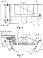
- the laser exposure apparatus of Fig. 1 comprises a relatively heavy base member 1 of for instance granite or metal, and an optical scanning unit 2 employing a movable, preferably rotating mirror for deflecting a laser beam directed towards a semi-cylindrical exposure surface 5 on the base member. Exposure material, such as a light-sensitive offset printing plate, can be placed on the above exposure surface 5.
- a bridge 7 is arranged above the base member 1, said bridge carrying the scanning unit and the mirror. The bridge is displaceable along the base member 1 in one direction thereof, cf. the double arrow A in Fig. 3, by means of an advancing device 8. The advancing device is arranged along one side 1a of the base member 1 in the entire length thereof.
- the bridge is mounted in a completely or almost completely balanced manner relative to the advancing device 8, whereby a projecting counterweight 9 is provided on the portion 7' of the bridge 7 projecting beyond the advancing device 8.
- the counterweight has a centre of gravity G, cf. Fig. 1, placed opposite to the optical scanning unit 2 relative to the advancing device 8 and in the vicinity of said device.
- the bridge 7 can optionally rest on the base member at some longitudinal supporting surfaces 10', 10'', 10''' on the latter.
- the support of the bridge at the supporting surfaces 10', 10'', 10''' can be provided by means of non-contact bearings 11', 11'', 11'''.
- These bearings can for instance be air-cushion bearings or magnetic bearings.
- One or more of the above supporting surfaces can be inclined relative to the longitudinal centre plane L of the base member 1, only one inclined supporting surface being shown in the embodiment shown in the Figures, viz. the supporting surface 10''.
- two non-contact bearings 11''a and 11''b can be provided between the counterweight 9 and the base member 1 at the inclined supporting surface 10'', and two non-contact bearings 11'a and 11'b can be provided at the substantially vertical supporting surface 10'.
- the supporting surface 10''' is substantially horizontal at the end 7'' of the bridge 7 being farthest away from the counterweight.
- the advancing device 8 can be a screw drive, a stepping motor device, a DC motor without brushes or an accurate cable or chain drive with a speed control.
- the advance device is a screw drive.
- Fig. 3 the bridge 7 is placed at one end of the base member.
- the bridge can be moved to the opposite end of the base member as illustrated.
- the bridge can also be made of steel or granite, and the counterweight can be made of steel.
- the device of the scanning unit 2 can be built of a rotatable polygonal mirror deflecting a laser beam from a laser fixed on the bridge.
- the laser beam is turned on and off in a conventional manner.
- the common centre of gravity of the bridge 7, the exposure equipment and of the counterweight 9 mounted thereon is placed substantially vertically above or below or within the advancing device 8.
- the invention can be modified in many ways without thereby deviating from the scope thereof.
Landscapes
- Physics & Mathematics (AREA)
- General Physics & Mathematics (AREA)
- Exposure And Positioning Against Photoresist Photosensitive Materials (AREA)
- Semiconductor Lasers (AREA)
- Laser Surgery Devices (AREA)
- Mechanical Optical Scanning Systems (AREA)
Claims (8)
- Appareil d'exposition à laser pour exposer un matériau d'exposition (6) comme des plaques d'impression offset sensibles à la lumière, ledit appareil comprenant un élément de base relativement lourd, par exemple, du granit et une unité de balayage optique (2) utilisant un miroir mobile pour dévier un faisceau laser et où l'élément de base (1) comprend une surface d'exposition plane ou semi-cylindrique (5) sur laquelle le matériau d'exposition (6) peut être placé et où un pont (7) est disposé au-dessus de l'élément de base (1), ledit pont étant susceptible d'être déplacé le long de l'élément de base dans une direction au moyen d'un dispositif d'avance (8), le miroir étant monté sur ledit pont, caractérisé en ce que le dispositif d'avance (8) est disposé sur et le long d'un côté (1a) de l'élément de base (1), en ce que le pont est monté d'une façon sensiblement équilibrée par rapport au dispositif d'avance (8) au moyen d'un contrepoids (9) prévu sur une partie se prolongeant (7') du pont (7), le centre de gravité dudit contrepoids (9) étant placé à l'opposé de l'unité de balayage optique (2) par rapport au dispositif d'avance (8) et au voisinage dudit dispositif, et en ce que le pont (7) prend appui sur des surfaces de support (10', 10'', 10''') sur l'élément de base (1).
- Appareil d'exposition au laser selon la revendication 1, caractérisé en ce que le pont (7) prend appui sur des surfaces de support longitudinales (10', 10'', 10''') sur l'élément de base.
- Appareil d'exposition à laser selon la revendication 1 ou 2, caractérisé en ce que le pont (7) prend appui sur les surfaces de support longitudinales (10', 10'', 10''') au moyen de supports sans contact (11'a, 11'b, 11''a, 11''b, 11''') comme des supports à coussin d'air ou des supports magnétiques.
- Appareil d'exposition à laser selon la revendication 1, 2 ou 3, caractérisé en ce qu'au moins l'une des surfaces de support (10'') est inclinée par rapport au plan central longitudinal (L) de l'élément de base (1).
- Appareil d'exposition à laser selon l'une ou plusieurs des revendications 1 à 4, caractérisé en ce que le contrepoids (9) est formé d'un seul tenant avec le pont (7).
- Appareil d'exposition à laser selon l'une ou plusieurs des revendications 1 à 5, caractérisé en ce que les paliers sans contact (11''a, 11''b, 11'a, 11'b) sont prévus entre le contrepoids (9) et l'élément de base (1) sur une surface de support inclinée (10'') et/ou une surface de support sensiblement verticale (10') respectivement sur l'élément de base (1) et en ce qu'un troisième support sans contact (11''') est prévu à l'extrémité (7'') du pont (7) la plus éloignée du contrepoids (9), ledit troisième support sans contact (11''') coopérant avec une surface de support sensiblement horizontale (10''') sur l'élément de base (1).
- Appareil d'exposition à laser selon l'une ou plusieurs des revendications 1 à 6, caractérisé en ce que le centre commun de gravité du pont (7), de l'agencement et du contrepoids monté sur celui-ci est positionné sensiblement verticalement au-dessus ou en dessous ou dans le dispositif d'avance (8).
- Appareil d'exposition à laser selon l'une ou plusieurs des revendications 1 à 7, caractérisé en ce que le dispositif d'avance (8) est un dispositif d'avance à moteur pas à pas, un entraínement à vis, un dispositif d'avance à moteur à courant continu sans balai ou un entraímement à chaíne ou à câble précis avec une commande de vitesse.
Applications Claiming Priority (3)
| Application Number | Priority Date | Filing Date | Title |
|---|---|---|---|
| DK17295 | 1995-05-02 | ||
| DK9500172U DK9500172U3 (da) | 1995-05-02 | 1995-05-02 | Lasereksponeringsapparat |
| PCT/DK1996/000200 WO1996034747A1 (fr) | 1995-05-02 | 1996-05-01 | Appareil d'exposition a laser |
Publications (2)
| Publication Number | Publication Date |
|---|---|
| EP0824399A1 EP0824399A1 (fr) | 1998-02-25 |
| EP0824399B1 true EP0824399B1 (fr) | 1999-08-18 |
Family
ID=8155172
Family Applications (1)
| Application Number | Title | Priority Date | Filing Date |
|---|---|---|---|
| EP96913476A Expired - Lifetime EP0824399B1 (fr) | 1995-05-02 | 1996-05-01 | Appareil d'exposition a laser |
Country Status (7)
| Country | Link |
|---|---|
| US (1) | US5909236A (fr) |
| EP (1) | EP0824399B1 (fr) |
| AT (1) | ATE183440T1 (fr) |
| AU (1) | AU5644496A (fr) |
| DE (1) | DE69603845T2 (fr) |
| DK (1) | DK9500172U3 (fr) |
| WO (1) | WO1996034747A1 (fr) |
Families Citing this family (2)
| Publication number | Priority date | Publication date | Assignee | Title |
|---|---|---|---|---|
| WO2000049463A1 (fr) * | 1999-02-17 | 2000-08-24 | Kodak Polychrome Graphics Company Ltd. | Système support de composition à plaque et à plat |
| DE60237252D1 (de) * | 2001-02-07 | 2010-09-23 | Dainippon Screen Mfg | Bildaufzeichnungsgerät |
Family Cites Families (5)
| Publication number | Priority date | Publication date | Assignee | Title |
|---|---|---|---|---|
| CH497714A (de) * | 1968-03-16 | 1970-10-15 | Bio Bielefelder Offsetdruckpla | Kopiergerät für Offsetdruckplatten |
| US4099800A (en) * | 1977-05-26 | 1978-07-11 | The Bendix Corporation | Coordinate measuring machine having auxiliary air bearing |
| US4455641A (en) * | 1978-09-12 | 1984-06-19 | Dennesen Electrostatics, Inc. | Linear tracking system |
| DK207090D0 (da) * | 1990-08-29 | 1990-08-29 | Andersen Allan V | Fremgangsmaade og apparat til udfoerelse af tromlescanning |
| JP2742006B2 (ja) * | 1993-09-22 | 1998-04-22 | 大日本スクリーン製造株式会社 | 円筒内面走査装置 |
-
1995
- 1995-05-02 DK DK9500172U patent/DK9500172U3/da not_active IP Right Cessation
-
1996
- 1996-05-01 AT AT96913476T patent/ATE183440T1/de not_active IP Right Cessation
- 1996-05-01 EP EP96913476A patent/EP0824399B1/fr not_active Expired - Lifetime
- 1996-05-01 WO PCT/DK1996/000200 patent/WO1996034747A1/fr not_active Ceased
- 1996-05-01 DE DE69603845T patent/DE69603845T2/de not_active Expired - Fee Related
- 1996-05-01 US US08/952,317 patent/US5909236A/en not_active Expired - Fee Related
- 1996-05-01 AU AU56444/96A patent/AU5644496A/en not_active Abandoned
Also Published As
| Publication number | Publication date |
|---|---|
| DE69603845T2 (de) | 2000-01-20 |
| EP0824399A1 (fr) | 1998-02-25 |
| WO1996034747A1 (fr) | 1996-11-07 |
| DK9500172U3 (da) | 1996-08-02 |
| DE69603845D1 (de) | 1999-09-23 |
| AU5644496A (en) | 1996-11-21 |
| US5909236A (en) | 1999-06-01 |
| ATE183440T1 (de) | 1999-09-15 |
Similar Documents
| Publication | Publication Date | Title |
|---|---|---|
| US6683433B2 (en) | Exposure apparatus and method utilizing isolated reaction frame | |
| ES2071239T3 (es) | Aparato de mecanizacion. | |
| KR960024695A (ko) | 노광 장치 | |
| IT1247367B (it) | Centro monoblocco per taglio automatico di lastre di pietra come marmo, granito e simili | |
| US5909236A (en) | Laser exposure apparatus | |
| US5101223A (en) | Image-reproducing apparatus | |
| ES2101414T3 (es) | Procedimiento para el cambio de las herramientas de recorte en una prensa de platinas y dispositivo para su realizacion. | |
| US5658186A (en) | Jig for polishing the edge of a thin solid state array panel | |
| TR200000493A2 (tr) | Tünellerin kapatılması ve tünel muhafazalarının açığa çıkarılması için tertibat | |
| JPH11503532A (ja) | プレートセッタ | |
| JPH06262383A (ja) | レーザ加工装置 | |
| CA2155883A1 (fr) | Appareil de montage de scanner pour imprimante electrostatique | |
| JP3299279B2 (ja) | シリンダー,特に抄紙機のローラの表面を研磨するための装置 | |
| RU2002121501A (ru) | Установка для формования и маркировки объекта и установка для изготовления укупорочных язычков для вскрытия банок | |
| JPH0646125Y2 (ja) | 画像読取装置 | |
| ATE112052T1 (de) | Ladeeinrichtung für dynamische wiegemaschinen. | |
| JPH0222740Y2 (fr) | ||
| US6556232B2 (en) | Base structure, processing device, and image forming device | |
| DE59913846D1 (de) | Lagerung für einen Spiegel zur Führung eines Laserstrahls an einer Laserbearbeitungsmaschine sowie Spiegelflächenträger als Teil einer derartigen Lagerung | |
| JP2023125419A (ja) | 金型装置 | |
| JPH10137969A (ja) | レーザ加工機の加工テーブル | |
| JPH044989A (ja) | レーザ加工機 | |
| JPH10337902A (ja) | 記録装置 | |
| JPH0734575B2 (ja) | 原稿読取装置 | |
| KR19990039741U (ko) | 반도체 웨이퍼 노광장비의 스테이지 기울어짐 검출장치 |
Legal Events
| Date | Code | Title | Description |
|---|---|---|---|
| PUAI | Public reference made under article 153(3) epc to a published international application that has entered the european phase |
Free format text: ORIGINAL CODE: 0009012 |
|
| 17P | Request for examination filed |
Effective date: 19971028 |
|
| AK | Designated contracting states |
Kind code of ref document: A1 Designated state(s): AT BE CH DE DK ES FR GB IT LI NL SE |
|
| GRAG | Despatch of communication of intention to grant |
Free format text: ORIGINAL CODE: EPIDOS AGRA |
|
| 17Q | First examination report despatched |
Effective date: 19980805 |
|
| GRAG | Despatch of communication of intention to grant |
Free format text: ORIGINAL CODE: EPIDOS AGRA |
|
| GRAH | Despatch of communication of intention to grant a patent |
Free format text: ORIGINAL CODE: EPIDOS IGRA |
|
| GRAH | Despatch of communication of intention to grant a patent |
Free format text: ORIGINAL CODE: EPIDOS IGRA |
|
| GRAA | (expected) grant |
Free format text: ORIGINAL CODE: 0009210 |
|
| AK | Designated contracting states |
Kind code of ref document: B1 Designated state(s): AT BE CH DE DK ES FR GB IT LI NL SE |
|
| PG25 | Lapsed in a contracting state [announced via postgrant information from national office to epo] |
Ref country code: SE Free format text: THE PATENT HAS BEEN ANNULLED BY A DECISION OF A NATIONAL AUTHORITY Effective date: 19990818 Ref country code: NL Free format text: LAPSE BECAUSE OF FAILURE TO SUBMIT A TRANSLATION OF THE DESCRIPTION OR TO PAY THE FEE WITHIN THE PRESCRIBED TIME-LIMIT Effective date: 19990818 Ref country code: LI Free format text: LAPSE BECAUSE OF FAILURE TO SUBMIT A TRANSLATION OF THE DESCRIPTION OR TO PAY THE FEE WITHIN THE PRESCRIBED TIME-LIMIT Effective date: 19990818 Ref country code: FR Free format text: LAPSE BECAUSE OF FAILURE TO SUBMIT A TRANSLATION OF THE DESCRIPTION OR TO PAY THE FEE WITHIN THE PRESCRIBED TIME-LIMIT Effective date: 19990818 Ref country code: ES Free format text: THE PATENT HAS BEEN ANNULLED BY A DECISION OF A NATIONAL AUTHORITY Effective date: 19990818 Ref country code: CH Free format text: LAPSE BECAUSE OF FAILURE TO SUBMIT A TRANSLATION OF THE DESCRIPTION OR TO PAY THE FEE WITHIN THE PRESCRIBED TIME-LIMIT Effective date: 19990818 Ref country code: BE Free format text: LAPSE BECAUSE OF FAILURE TO SUBMIT A TRANSLATION OF THE DESCRIPTION OR TO PAY THE FEE WITHIN THE PRESCRIBED TIME-LIMIT Effective date: 19990818 Ref country code: AT Free format text: LAPSE BECAUSE OF FAILURE TO SUBMIT A TRANSLATION OF THE DESCRIPTION OR TO PAY THE FEE WITHIN THE PRESCRIBED TIME-LIMIT Effective date: 19990818 |
|
| REF | Corresponds to: |
Ref document number: 183440 Country of ref document: AT Date of ref document: 19990915 Kind code of ref document: T |
|
| REG | Reference to a national code |
Ref country code: CH Ref legal event code: EP |
|
| REF | Corresponds to: |
Ref document number: 69603845 Country of ref document: DE Date of ref document: 19990923 |
|
| ITF | It: translation for a ep patent filed | ||
| PG25 | Lapsed in a contracting state [announced via postgrant information from national office to epo] |
Ref country code: DK Free format text: LAPSE BECAUSE OF FAILURE TO SUBMIT A TRANSLATION OF THE DESCRIPTION OR TO PAY THE FEE WITHIN THE PRESCRIBED TIME-LIMIT Effective date: 19991118 |
|
| EN | Fr: translation not filed | ||
| NLV1 | Nl: lapsed or annulled due to failure to fulfill the requirements of art. 29p and 29m of the patents act | ||
| REG | Reference to a national code |
Ref country code: CH Ref legal event code: PL |
|
| PGFP | Annual fee paid to national office [announced via postgrant information from national office to epo] |
Ref country code: GB Payment date: 20000426 Year of fee payment: 5 |
|
| PGFP | Annual fee paid to national office [announced via postgrant information from national office to epo] |
Ref country code: DE Payment date: 20000519 Year of fee payment: 5 |
|
| PLBE | No opposition filed within time limit |
Free format text: ORIGINAL CODE: 0009261 |
|
| STAA | Information on the status of an ep patent application or granted ep patent |
Free format text: STATUS: NO OPPOSITION FILED WITHIN TIME LIMIT |
|
| 26N | No opposition filed | ||
| PG25 | Lapsed in a contracting state [announced via postgrant information from national office to epo] |
Ref country code: GB Free format text: LAPSE BECAUSE OF NON-PAYMENT OF DUE FEES Effective date: 20010501 |
|
| GBPC | Gb: european patent ceased through non-payment of renewal fee |
Effective date: 20010501 |
|
| PG25 | Lapsed in a contracting state [announced via postgrant information from national office to epo] |
Ref country code: DE Free format text: LAPSE BECAUSE OF NON-PAYMENT OF DUE FEES Effective date: 20020301 |
|
| PG25 | Lapsed in a contracting state [announced via postgrant information from national office to epo] |
Ref country code: IT Free format text: LAPSE BECAUSE OF NON-PAYMENT OF DUE FEES;WARNING: LAPSES OF ITALIAN PATENTS WITH EFFECTIVE DATE BEFORE 2007 MAY HAVE OCCURRED AT ANY TIME BEFORE 2007. THE CORRECT EFFECTIVE DATE MAY BE DIFFERENT FROM THE ONE RECORDED. Effective date: 20050501 |