EP0825390A2 - Unité d'intérieur pour dispositif de conditionnement d'air - Google Patents
Unité d'intérieur pour dispositif de conditionnement d'air Download PDFInfo
- Publication number
- EP0825390A2 EP0825390A2 EP97305768A EP97305768A EP0825390A2 EP 0825390 A2 EP0825390 A2 EP 0825390A2 EP 97305768 A EP97305768 A EP 97305768A EP 97305768 A EP97305768 A EP 97305768A EP 0825390 A2 EP0825390 A2 EP 0825390A2
- Authority
- EP
- European Patent Office
- Prior art keywords
- air
- air outlet
- diffused
- vane
- indoor unit
- Prior art date
- Legal status (The legal status is an assumption and is not a legal conclusion. Google has not performed a legal analysis and makes no representation as to the accuracy of the status listed.)
- Granted
Links
Images








Classifications
-
- F—MECHANICAL ENGINEERING; LIGHTING; HEATING; WEAPONS; BLASTING
- F24—HEATING; RANGES; VENTILATING
- F24F—AIR-CONDITIONING; AIR-HUMIDIFICATION; VENTILATION; USE OF AIR CURRENTS FOR SCREENING
- F24F1/00—Room units for air-conditioning, e.g. separate or self-contained units or units receiving primary air from a central station
- F24F1/0007—Indoor units, e.g. fan coil units
- F24F1/0011—Indoor units, e.g. fan coil units characterised by air outlets
-
- F—MECHANICAL ENGINEERING; LIGHTING; HEATING; WEAPONS; BLASTING
- F24—HEATING; RANGES; VENTILATING
- F24F—AIR-CONDITIONING; AIR-HUMIDIFICATION; VENTILATION; USE OF AIR CURRENTS FOR SCREENING
- F24F1/00—Room units for air-conditioning, e.g. separate or self-contained units or units receiving primary air from a central station
- F24F1/0007—Indoor units, e.g. fan coil units
- F24F1/0043—Indoor units, e.g. fan coil units characterised by mounting arrangements
- F24F1/0057—Indoor units, e.g. fan coil units characterised by mounting arrangements mounted in or on a wall
-
- F—MECHANICAL ENGINEERING; LIGHTING; HEATING; WEAPONS; BLASTING
- F24—HEATING; RANGES; VENTILATING
- F24F—AIR-CONDITIONING; AIR-HUMIDIFICATION; VENTILATION; USE OF AIR CURRENTS FOR SCREENING
- F24F13/00—Details common to, or for air-conditioning, air-humidification, ventilation or use of air currents for screening
- F24F13/02—Ducting arrangements
- F24F13/06—Outlets for directing or distributing air into rooms or spaces, e.g. ceiling air diffuser
Definitions
- the present invention relates to an indoor unit for an air conditioner which has an essential part constituted by a cross flow fan.
- Figures 15 and 16 there is shown an indoor unit for an air conditioner which is similar to a conventional air conditioner indoor unit disclosed in e.g. JP-Y-749288.
- Figure 15 is a vertical sectional view of the indoor unit
- Figure 16 is a schematic view to show how air is diffused from the indoor unit of Figure 15.
- reference 1 designates a housing for the indoor unit prepared as a separate type air conditioner, which is installed in a room (not shown), and which has an essential part constituted by a cross flow fan.
- Reference numeral 2 designates an impeller of the cross flow fan.
- Reference numeral 3 designates a diffused air path which is arranged downstream the impeller 2, i.e. on an air outlet side of the impeller 2, and opens on the housing 1.
- the diffused air path is constituted by a rear side plate 4 forming a rear side and a front side plate 5 forming a front side, and is formed with an air outlet 6.
- Reference numeral 7 designates two vanes which are apart from each other in the air outlet 6 and are arranged in parallel therein in a longitudinal direction thereof, and which are pivoted on the air outlet 6 through horizontal shafts so as to be swingable within a range of an angle E as shown in Figure 15.
- Reference numeral 8 designates a heat exchanger which is arranged upstream the impeller 2 in the housing 1.
- the conventional air conditioner indoor unit is constructed as stated earlier, and the impeller 2 is driven by an electric motor (not shown) for rotation to give energy to air, supplying the air in a raised pressure.
- the air supplied in such a raise pressure is directed through the diffused air path 3, which is formed in a linearly tapered form with a constant expanding angle to gradually expand toward the air outlet 6, directs the supplied air to the air outlet 6, and blows the supplied air out off the air outlet 6 as shown by arrows P in Figure 16.
- Such an arrangement allows the diffused air path 3 to realize the static pressure regain of the diffused air to some extent and to establish a diffusing function to some extent.
- the vanes 7 can be driven by a driving device (not shown) to change their positions, controlling the issuing direction of the diffused air.
- the indoor air When indoor air passes through the heat exchanger 8, the indoor air is subjected to heat exchange to become cool air or warm air, and the cool air or the warm air is blown out off the air outlet 6 into the room to carry out an air conditioning function.
- the diffusing function by the diffused air path 3 is insufficient, which requires that the expanding angle of the diffused air path 3 be great.
- the expanding angle of the diffused air path 3 is excessively great, the diffused air becomes unstable to increase noise.
- an air conditioner indoor unit comprising a housing; an impeller arranged in the housing and forming a cross flow fan; a rear side plate arranged downstream the impeller and forming a rear side of a diffused air path; a front side plate forming a front side of the diffused air path and including a first air outlet surface, a second air outlet surface and a third air outlet surface; the first air outlet surface arranged near to the impeller and having a portion on a side of an air outlet of the diffused air path slanted in a direction away from a reference surface defined by the rear side plate; the second air outlet surface arranged next to the first air outlet surface on the side of the air outlet and having a portion on the side of the air outlet slanted in a direction away from the reference surface; and the third air outlet surface arranged next to the second air outlet surface on the side of the air outlet end and having a portion on the side of the air outlet slanted at 20° - 30° in the
- the reference surface means an outermost surface of the rear side plate on the side of the air outlet, which is indicated by 10 in Figure 10, and which is parallel with the first air outlet surface.
- an air conditioner indoor unit wherein the first air outlet surface has the portion on the side of the air outlet slanted at 0° - 5° in a direction away from the reference surface, the second air outlet surface has the portion on the side of the air outlet slanted at 7°- 15° in the direction away from the reference surface, and the first, second and third air outlet surfaces have each of connected portions therebetween formed with a curved surface so as to provide a successively changed slant.
- an air conditioner indoor unit wherein a ratio of depth size of the first air outlet surface to height size of the diffused air path, a ratio of depth size of the second air outlet surface to the height size of the diffused air path and a ratio of depth size of the third air outlet surface to the height size of the diffused air path are respectively set to not less than 0.3.
- an air conditioner indoor unit wherein there are provided an edge portion forming an air outlet edge of the rear side plate and a deflecting member arranged on the rear side plate near to the air outlet and located nearer to the impeller than the edge portion, depth size of the deflecting portion in the air outlet along an diffusing direction is not greater than 0.3 times the height size of the diffused air path, and the deflecting portion has an upper surface with a leading portion and a base portion, the leading edge arranged to be slanted at 10° - 25° in a direction away from the reference surface in comparison with the base portion so as to direct an air flow along the rear side plate in the diffused air path to a direction along a vane provided in the air outlet.
- an air conditioner indoor unit wherein a vane is arranged in the air outlet and is pivoted therein through a horizontal axis so as to make a position controllable, the vane is set at a first position to diffuse cool air generated by the cross flow fan in a horizontal or upward direction on start-up, the vane is displaced from the first position to a second position to diffuse the air more downwardly than the vane in the first position after elapse of a vapor condensation limit time for cool air supplied by the vane in the first position so as to eliminate vapor condensation on the vane, and the vane is returned to the first position after elimination of the vapor condensation, the vapor condensation limit time determined based on a diffused air temperature of the cool air, and a temperature and a humidity in a room with the indoor unit installed.
- an air conditioner indoor unit wherein the vane in the second position has a lower diffusing speed of the cool air than the vane in the first position.
- an air conditioner indoor unit wherein a vane is arranged in the air outlet and is pivoted therein through a horizontal shaft so as to make a position controllable, and a frame member for having a vane drive motor fixed thereto is provided with a receiving portion for supporting the shaft.
- an air conditioner indoor unit wherein a vane is arranged in the air outlet and is pivoted therein through a horizontal shaft so as to make a position controllable, and a frame member for having a vane drive motor fixed thereto is provided with a hole for supporting the shaft.
- an air conditioner indoor unit wherein the frame member is made of a material different from the shaft, and the frame member is integrally provided with a bearing portion having the hole for receiving the shaft in the eighth aspect.
- an air conditioner indoor unit wherein the air outlet is made of an air outlet member, the air outlet member is formed with a through hole, the bearing portion is formed to project from the frame member, and the bearing portion is inserted in the through hole in the air outlet member in the ninth aspect.
- the third air outlet surface has the portion on the side of the air outlet slanted at 25 - 30° in the direction away from the reference surface, allowing the diffused air path to regain a dynamic pressure of air sucked by the cross flow fan to a static pressure in a sufficient manner, and conditioned air to be diffused without coming off the front side plate.
- an effective diffusing function can be obtained to make the diffused air stable, obtaining quiet operation and a required diffusing function by the diffused air path.
- the first air outlet surface, the second air outlet surface and the third air outlet surface have the respective portions on the side of the air outlet slanted in the direction away from the reference surface, allowing the diffused air path to regain the dynamic pressure of the suction air by the cross flow fan to a static pressure in a sufficient manner, and the diffused air to be blown off in a wide range without coming off the front side plate.
- an effective diffusing function can be obtained to make the diffused air stable, obtaining quiet operation and a required diffusing function by the diffused air path.
- the third air outlet surface as the portion of the side of the air outlet slanted at 20° - 30° in the direction away from the reference surface, allowing the diffused air path to regain the dynamic pressure of the suction air by the cross flow fan to a static pressure in a sufficient manner, and the diffused air to be blown off without coming off the front side plate.
- an effective diffusing function can be obtained to make the diffused air stable, obtaining quiet operation and a required diffusing function by the diffused air path.
- the dynamic pressure of the suction air generated by the impeller of the cross flow fan can be regained to a static pressure in a sufficient manner by providing the diffused air path with such a structure that the ratio of the depth size of each of the air outlet surfaces to the height size of the diffused air path is set to not to less than 0.3.
- Such arrangement can offer such a diffusing function that air volume increases when the impeller rotates at the same speed and noise decreases when the same air volume is maintained.
- the third air outlet surface as the portion on the side of the air outlet slanted at 20° - 30° in the direction away from the reference surface, allowing the diffused air path to regain the dynamic pressure of the suction air by the cross flow fan to a static pressure in a sufficient manner, and the conditioned air to be diffused without coming off the front side plate.
- an effective diffusing function can be obtained to make the diffused air stable, obtaining quiet operation and a required diffusing function by the diffused air path.
- the deflecting portion is arranged on the rear side plate near to the air outlet to be slanted at 10 - 25 ° in the direction away from the reference surface, it is easy to obtain a required horizontal air flow or downward air flow even if a vane arranged in the air outlet is set at a small deflection angle.
- the air outlet pressure loss of the horizontal air flow or downward air flow by the vane can be minimized, offering an advantage in that diffusing performance can be obtained with an increased air volume in comparison with a case with the same air flow direction and the same noise.
- the depth size of the deflecting portion in the air outlet in the diffusing direction is not greater than 0.3 times the height size of the diffused air path. As a result, it is easy to obtain a required horizontal air flow or downward air flow even if the vane is set at a small deflection angle.
- FIGs 1 - 5 there is shown a first embodiment of the present invention.
- Figure 1 there is shown a vertical sectional view of the air conditioner indoor unit according to the first embodiment.
- Figure 2 it is shown how conditioned air is diffused from the indoor unit of Figure 1.
- Figures 3(a) - (c) there are shown graphs showing the characteristics of noise and air volume relevant to the structure of a diffused air path stated later.
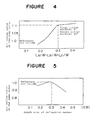
- Figure 4 there is shown a graph showing the characteristics of noise and air volume relevant to depth size of air outlet surfaces in the diffused air path stated later.
- Figure 5 there is shown a graph showing the characteristics of noise and air volume relevant to depth size of a deflecting member in the diffused air path stated later.
- reference numeral 1 designates a housing for a separate type air conditioner which is installed in a room (not shown), and which has an essential part constituted by a cross flow fan.
- Reference numeral 2 designates an impeller of the cross flow fan.
- Reference numeral 3 designates a diffused air path which is arranged downstream the impeller 2, i.e. on an air outlet side, and opens on the housing 1, which is constituted by a rear side plate 4 forming a rear side and a front side plate 5 forming a front side, and which is constructed as stated later and is formed with an air outlet 6.
- Reference numeral 7 designates a plurality of vanes (two vanes in Figure 1) which are apart from each other in the air outlet 6 and are arranged in parallel in the air outlet 6 in a longitudinal direction thereof, which are pivoted to the air outlet 6 through horizontal axes, and which are arranged to be swingable within a range of an angle E.
- Reference numeral 8 designates an heat exchanger which is upstream the impeller 2 in the housing 1.
- the front side plate 5 is constituted by a first air outlet surface, a second air outlet surface and a third air outlet surface which will be explained.
- reference numeral 9 designates the first air outlet surface which is located near to the impeller 2, and which has a portion on a side of the air outlet of the diffused air path 3 arranged in a direction away from reference surface 10 defined by the rear side plate 4 so as to be slanted at 0° - 5° with respect to the reference surface 10 in an angle X shown in Figure 1.
- Reference numeral 11 designates the second air outlet surface which is located next to the first air outlet surface 9 on the side of the air outlet, and which has a portion of the side of air outlet of the diffused air path 3 arrange din a direction away from the reference surface 10 so as to be slanted at 7° - 15° with respect to the reference surface 10 in an angle Y shown in Figure 1.
- Reference numeral 12 designates the third air outlet surface which is located next to the second air outlet surface 11 on the side of the air outlet, and which has a portion on the side of the air outlet of the diffused air path 3 arranged in a direction away from the reference surface 10 so as to be slanted at 20° - 30° with respect to the reference surface 10 in an angle Z in Figure 1.
- the first air outlet surface 9, the second air outlet surface 11 and the third air outlet surface 12 have each of connected portions therebetween formed with a curved surface so as to provide a successively changed slant.
- reference LA designates depth size of the first air outlet surface 9
- reference LB designates depth size of the second air outlet surface 11
- reference LC designates depth size of the third air outlet surface 12
- reference W designates height size of the diffused air path.
- Reference numeral 13 designates a deflecting member which is located on the rear side plate 4 near to the air outlet 6 and is arranged in parallel with the air outlet 6 in the longitudinal direction thereof, which has a leading portion arranged in a direction away from the reference surface 10 in comparison with a base portion thereof, and which has an upper surface placed so as to be slanted at 10° - 25° with respect to the reference surface 10 in an angle ⁇ shown in Figure 1.
- the length of the deflecting member 13 in a diffusing direction at the air outlet 6, i.e. the depth size of the deflecting member is set to not greater than 0.3 times the height size of the diffused air path.
- Reference numeral 131 designates an edge portion which is provided on the rear side plate 4 nearer to the air outlet 6 than the deflecting member 13, and which forms the edge of the air outlet 6.
- Reference numeral 14 designates a front vane which is placed next to the third air outlet surface 12 on the side of the air outlet 6, and which is arranged in parallel with the air outlet 6 in the longitudinal direction thereof.
- the impeller 2 is driven by an electric motor (not shown) for rotation to give energy to air, supplying the air in a raised pressure.
- the diffused air path 3 is constituted as follows. Specifically, the diffused air path is provided with a structure shown in Figure 2 by the first air outlet surface 9, the second air outlet surface 11 and the third air outlet surface 12, i.e. is formed so that the diffused air path is constituted by the rear side plate 4 and the front side plate 5 curved in a convex shape with an intermediate portion in the depth direction projected in a vertical section, and that the front side is thus curved to provide a divergent shape to the diffusing air path on the side of the air outlet 6.
- a flow of of the air supplied in such a raised pressure is directed through the diffused air path 3, and is blown out off the air outlet 6 as shown by arrows Q in Figure 2.
- the diffused air path 3 allows the diffused air to regain a static pressure and a diffusing function to be created.
- the direction of the diffused air can be controlled by using a driving device (not shown) to drive the vanes 7 so as to change the positions of the respective vanes.
- the air When indoor air is passing through the heat exchanger 8, the air is subjected to heat exchange to become cool air or warm air, and the cool air or the warm air is blown out off the air outlet 6 into the room, carrying out air conditioning.
- the third air outlet surface 12 is arranged to be slanted at 20° - 30° with respect to the reference surface 10 in the angle Z shown in Figure 1. This allows the diffusing air path 3 to regain the dynamic pressure of air sucked by the cross flow fan to a static pressure in an effective manner.
- the diffused air can be blown out off without coming off the front side plate 5.
- an effective diffusing function can be obtained to make the diffused air stable, reducing noise and obtaining a diffusing function required for the diffused air by the diffused air path 3.
- the first air outlet surface 9 is arranged to be slanted at 0° - 5° with respect to the reference surface 10 in the angle X shown in Figure 1.
- the second air outlet surface 11 is arranged to be slanted 7° - 15° with respect to the reference surface 10 in the angle Y shown in Figure 1.
- the third air outlet surface 12 is arranged to be slanted at 20° - 30° with respect to the reference surface 10 in the angle Z shown in Figure 1. This arrangement allows the diffused air path 3 to blow out the diffused air in a wide range as shown by the arrows Q in Figure 2 according to the characteristics shown in Figures 3(a) - (c).
- the deflection angle of the vanes 7 which are arranged in the air outlet 6 to obtain a horizontal air flow or downward air flow can be made small.
- diffusing pressure loss of the horizontal air flow or downward air flow by the vanes 7 can be minimized to prevent the air volume from decreasing or noise from increasing, offering advantages in that quiet operation can be established and required diffusing performance can be obtained easily.
- the depth size LA of the first air outlet surface 9, the depth size LB of the second air outlet surface 11 and the depth size LC of the third air outlet surface 12 to the height size W of the diffused air path 3 shown in Figure 1 are set to satisfy the requirement of LA/W, LB/W, LC/W ⁇ 0.3. It is possible to regain the dynamic pressure of the suction air caused by the impeller 2 of the cross flow fan to a static pressure in a sufficient manner by providing the diffused air path 3 with a shape satisfying the requirement.
- the deflecting member 13 is arranged on the rear side plate 4 near to the air outlet 6, and the deflection member has the upper surface arranged to be slanted at 10° - 25° with respect to the reference surface 10 in the angle ⁇ shown in Figure 1.
- the length of the deflecting member 13 along the diffusing direction in the air outlet 6, i.e. the depth size of the deflecting member is set to not greater than 0.3 times the height size of the diffused air path 3.
- Such arrangement can obtain a required horizontal air flow or downward air flow easily even if the vanes 7 are set at a small deflection angle.
- the deflection angle of the vanes 7 can be minimized with keeping the horizontal air flow or downward air flow at the same direction.
- the diffusing pressure loss of the horizontal air flow or downward air flow by the vanes 7 can be minimized, obtaining such diffusing performance that the air volume increases in comparison with a case with the same air flow and the same noise as seen from the characteristics shown in Figure 5.
- FIG 6 there is shown a view of a second embodiment of the present invention, which is similar to Figure 1.
- the air conditioner indoor unit according to the second embodiment is constituted in the same manner as the embodiment shown in Figures 1 - 5 except for features shown in Figure 6.
- identical or corresponding parts are indicated by the same reference numeral as those in Figures 1 - 5.
- Reference numeral 15 designates a deflecting member which is located on the rear side plate 4 near to the air outlet 6, and which is arranged in parallel with the air outlet 6 in the longitudinal direction thereof.
- the deflecting member has a leading portion arranged in a direction away from the reference surface 10 in comparison with a base portion thereof.
- the deflecting member has an upper surface arranged to be slanted at a suitable angle with respect to the reference surface 10 as shown in Figure 6.
- the deflecting member has a dented recess formed near to the air outlet 6.
- the length of the deflection member 15 along the diffusing direction in the air outlet 6, i.e. the depth size of the deflecting member is set to not greater than 0.3 times the height size of the diffused air path 3.
- the impeller 2 is driven by the electric motor, and the diffused air path 3 is constituted by the rear side plate 4 and the front side plate 5 which is constituted by the first air outlet surface 9, the second air outlet surface 11 and the third air outlet surface 12.
- the deflecting member 15 and the leading vane 14 are also provided.
- the deflecting member 15 When the deflecting member 15 is made of a heat insulating material, the deflecting member can have improved resistance to vapor condensation when cooled air is passing through the diffused air path 3.
- the edge portion 131 on the rear side plate 4 which forms the edge of the air outlet 6, and the deflecting member 15 which is placed on the rear side plate 4 near to the air outlet 6 and is arranged nearer to the impeller 2 than the edge portion 131.
- Both members can provide the vented recess therebetween with good separation of the air flow with respect to the deflecting member 15 in the diffused air path 3 to avoid vapor condensation and can to carry out vapor condensation treatment more easily.
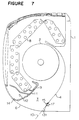
- FIG 7 there is shown a view of a third embodiment of the present invention, which is similar to Figure 1.
- the air conditioner indoor unit according to the third embodiment is constituted in the same manner as the embodiment of Figures 1 - 5 except for the features shown in Figure 7.
- identical or corresponding parts are indicated by the same reference numerals as those of Figures 1 - 5 and Figure 6.
- Reference numeral 17 designates a sheet with fluff which is attached to a rear side of the deflecting member 15 in a plate shape.
- the impeller 2 is driven by the electric motor, and the diffused air path 3 is constituted by the rear side plate 4 and the front side plate which is constituted by the first air outlet surface 9, the second air outlet surface 11 and the third air outlet surface 12.
- the deflecting member 15 and the leading vane 14 are also provided.
- FIGs 8 and 9 there is shown views of a fourth embodiment of the present invention.
- a flow chart to show an air flow control manner for the air conditioner indoor unit.
- Figure 9 there is shown a graph showing vapor condensation limit times in a horizontal air flow or upward air flow with respect to humidity at predetermined room temperatures and diffused air temperatures in the air flow control manner of Figure 9.
- FIGs 10 - 13 there are views to explain the air conditioner indoor unit.
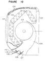
- Figure 10 there is shown a vertical sectional view of the indoor unit to explain how to control the air flow in the indoor unit.
- Figure 11 there is shown an enlarged view of the essential parts of Figure 10 to explain how conditioned air is diffused from the indoor unit of Figure 10.
- Figure 12 there is shown a vertical sectional view to explain a state of a room with the indoor unit of Figure 10 installed.
- Figure 13 there is shown a vertical sectional view to show another state of the room with the indoor unit of Figure 10 installed.
- reference numeral 101 designates the room where the indoor unit 102 is installed.
- reference numeral 103 designates an impeller which forms a cross flow fan arranged in the indoor unit 102.
- Reference numeral 104 designates air inlets which are arranged upstream the impeller 103.
- Reference numeral 105 designates a heat exchanger which is arranged between the air inlets 104 and the impeller 103.
- Reference numeral 106 designates a diffused air path which is arranged downstream the impeller 103.
- Reference numeral 107 designates an air outlet which communicates with the diffused air path 106 and opens on the indoor unit 102.
- Reference numeral 108 designates a plurality of vanes (two vanes in Figures 10 and 11) which are apart from each other in the air outlet 107 and are arranged in parallel in the air outlet 107 in the longitudinal direction thereof, and which are pivoted to the air outlet 107 through horizontal axes.
- the vanes are arranged to be swingable around respective pivoted axes as shown in Figure 10.
- Reference numeral 109 designates cooled air which is supplied by the cross flow fan.
- Reference numeral 110 designates air flows in the room 101.
- Reference numeral 111 designates vapor condensation which is deposited on lower surfaces of the vanes 8.
- the polygonal lines shown in Figures 12 and 13 designate isothermal lines in the room 101.
- the intermediate portion of the room 101 in the height direction is at a low temperature.
- air having a low temperature is flowing at a high position in the room 101.
- the air conditioner carries out cooling operation or dehumidifying operation as follows.
- the impeller 103 is driven by an electric motor (not shown) for rotation to diffuse cool air from the air outlet 107 through the diffused air path 106.
- the vanes 108 are swung by a driving device (not shown) to change the diffusing direction of the cool air.
- an upward diffusing mode selection is made at Step 114 to set the vanes 108 to the first position 112, diffusing the cool air 109 supplied by the cross flow fan in the horizontal or upward direction.
- a detection portion (not shown) which is provided in the room 101 detects the room temperature TR1 (°C) in the room 101, the diffused air temperature T (Ta>Tb>Tc) of the cool air 109 supplied by the cross flow fan, and the humidity in the room.
- the controller of the indoor unit carries out such a control operation to command the upward diffusing mode wherein the vanes 108 take the first position 112 to diffuse the cool air 109 supplied by the cross flow fan in the horizontal or upward direction for tw (min.) based on the room temperature TR1 (°C) in the room 101.
- the controller commands the downward mode with a short period of time wherein the vanes 108 take the second position 113 to diffuse the cool air 109 supplied by the cross flow fan in a direction which is more downward than the upward diffusing mode.
- the controller issues a command to repeat the upward diffusing mode and the downward diffusing mode.
- the humidity for a predetermined room temperature and a vapor condensation limit time for a diffused air temperature of the cool air 109 in the upward diffusing mode by the cross flow fan are set at a microcomputer of the controller so as to correspond to the room temperature TR1 (°C) in the room 101 according to the relation shown in Figure 9.
- the detection portion 115 detects factors such as the room temperature TR1 (°C), and the vapor condensation limit time tw (min.) is set by the setting operation 116 based in the results of the detection.
- the controller of the indoor unit issues the control operation 117 to carry out the upward blowing mode wherein the vanes 108 take the first position 112 to diffuse the cool air in the horizontal or upward direction for tw (min.).
- tw (min.) pass, the vanes 108 take the second position 113, and the downward blowing mode is carried out to diffuse the cool air 109 for a short period of time in the downward direction which is more downward than the upper blowing mode. After that, diffusing air by the upward blowing mode and diffusing air by the downward blowing mode are repeated.
- the upward blowing mode is normally carried out to set the vanes 108 to the first position 112 so as to diffuse the cool air 109 in the horizontal or upward direction.
- Such arrangement can solve a problem in that the cool air hits directly on a person in the room 101 to make him or her feel chilly or uncomfortable.
- the vanes 108 take the second position 113 to carry out the downward blowing mode for a short period of time to diffuse the cool air 106 in the downward direction which is more downward than the upward blowing mode.
- the vapor condensation 111 deposited on the lower surfaces of the vanes 108 is eliminated. In that manner, the time to hit the cool air directly on a person in the room can be minimized, obtaining a comfortable air conditioning function or a comfortable dehumidifying function which is free from problems due to an increase in the vapor condensation 111.
- the cool air has a lower diffusing speed than the cool air which is diffused when the vanes 108 take the first position 112.
- the cool air which is diffused when the vanes 108 take the second position 113 can have a low diffusing speed to weaken the cool air hitting on a person in the room, improving comfort during the cooling operation or the dehumidifying operation.
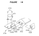
- reference numeral 201 designates a vane drive motor.
- Reference numeral 202 designates a frame which is constituted by an upper plate 203 and a side plate 204 combined in an L character shape, which has the side plate 204 formed integrally with a bearing portion 205 in a projection manner, and which has the bearing portion 205 formed with a through hole 205a.
- Reference numeral 206 designates screws for fixing the vane drive motor 201 to the frame 202.
- Reference numeral 207 designates an air outlet member which is fitted in the air outlet (not shown).
- Reference numeral 207a designates a through hole which is formed in a side surface of the air outlet member 207.
- Reference numeral 208 designates a vane which is housed in the air outlet member 207.
- Reference numeral 208a designates a shaft of the vane.
- the frame 202 is made of a material different from that of the vane 208.
- Reference numeral 209 designates a screw for fixing the frame 202 to the air outlet member 207.
- the vane drive motor 201 is assembled to the upper plate 203 of the frame 207, and the vane drive motor is fixed to the frame by the screws 206.
- the frame 202 thus assembled is assembled to the air outlet member 207 by inserting the bearing portion 205 of the side plate 204 into the through hole 207a of the air outlet member 207.
- the side plate 204 is fixed to the air outlet member 207 by the screw 209.
- the shaft 208a of the vane is inserted into the through hole 205a of the bearing portion 205.
- the through hole 205a of the bearing portion 205 works as a receiving portion for supporting the shaft 208a of the vane 208, and since the bearing portion 205 is integral with the frame 202, a bearing separate from the frame 2 is not necessary unlike prior art. As a result, the number of required parts and the number of required processes decrease, and required cost reduces. Because positioning of the frame 202 is carried out by inserting the bearing portion 205 into the through hole 207a of the air outlet member 207, the assembly can be made easily, and the number of required screws decreases. Since the frame 202 is made of a different material from the vane 208, the vane 208 can operates in a smooth manner.
- fixing the vane drive motor 201 is made by the screws 206 and fixing the frame 202 is made by the screw 209 in this embodiment, the fixing of both parts is not limited to use of screws. Another fixing member may be used to make the fixing of both parts.
Landscapes
- Engineering & Computer Science (AREA)
- Chemical & Material Sciences (AREA)
- Combustion & Propulsion (AREA)
- Mechanical Engineering (AREA)
- General Engineering & Computer Science (AREA)
- Air-Flow Control Members (AREA)
- Air Filters, Heat-Exchange Apparatuses, And Housings Of Air-Conditioning Units (AREA)
- Air-Conditioning Room Units, And Self-Contained Units In General (AREA)
- Air Humidification (AREA)
- Cooling Or The Like Of Electrical Apparatus (AREA)
Applications Claiming Priority (9)
| Application Number | Priority Date | Filing Date | Title |
|---|---|---|---|
| JP22235396 | 1996-08-23 | ||
| JP222354/96 | 1996-08-23 | ||
| JP222353/96 | 1996-08-23 | ||
| JP8222354A JPH1061999A (ja) | 1996-08-23 | 1996-08-23 | 空気調和機用室内機の風向制御方法 |
| JP22235396A JP3589803B2 (ja) | 1996-08-23 | 1996-08-23 | 空気調和機用室内機 |
| JP22235496 | 1996-08-23 | ||
| JP24936696A JP3458617B2 (ja) | 1996-09-20 | 1996-09-20 | 空気調和機のベーン駆動モータ取付装置及びその取付方法 |
| JP249366/96 | 1996-09-20 | ||
| JP24936696 | 1996-09-20 |
Publications (3)
| Publication Number | Publication Date |
|---|---|
| EP0825390A2 true EP0825390A2 (fr) | 1998-02-25 |
| EP0825390A3 EP0825390A3 (fr) | 1998-04-01 |
| EP0825390B1 EP0825390B1 (fr) | 2001-12-19 |
Family
ID=27330658
Family Applications (1)
| Application Number | Title | Priority Date | Filing Date |
|---|---|---|---|
| EP97305768A Expired - Lifetime EP0825390B1 (fr) | 1996-08-23 | 1997-07-31 | Unité d'intérieur pour dispositif de conditionnement d'air |
Country Status (7)
| Country | Link |
|---|---|
| US (1) | US5924923A (fr) |
| EP (1) | EP0825390B1 (fr) |
| AT (1) | ATE211243T1 (fr) |
| AU (1) | AU719205B2 (fr) |
| DE (1) | DE69709268D1 (fr) |
| ES (1) | ES2170334T3 (fr) |
| ID (1) | ID21279A (fr) |
Cited By (4)
| Publication number | Priority date | Publication date | Assignee | Title |
|---|---|---|---|---|
| ES2258372A1 (es) * | 2001-10-15 | 2006-08-16 | Lg Electronics Inc. | Unidad interior de aparato compacto de aire acondicionado. |
| EP1553361A4 (fr) * | 2002-09-25 | 2007-02-14 | Sharp Kk | Conditionneur d'air |
| CN102734866A (zh) * | 2011-04-13 | 2012-10-17 | 珠海格力电器股份有限公司 | 空调室内机及其运行控制方法 |
| EP2405206A4 (fr) * | 2009-03-06 | 2013-12-18 | Mitsubishi Electric Corp | Climatiseur |
Families Citing this family (16)
| Publication number | Priority date | Publication date | Assignee | Title |
|---|---|---|---|---|
| AU733063B2 (en) * | 1996-05-23 | 2001-05-03 | Techmetal Industries Pty Ltd | A diffuser for an air outlet |
| US6338676B1 (en) | 1998-12-28 | 2002-01-15 | Mitsubishi Denki Kabushiki Kaisha | Air conditioner |
| KR100315518B1 (ko) | 1999-09-10 | 2001-11-30 | 윤종용 | 공기 조화기의 횡류 팬 |
| DK1370810T3 (da) * | 2001-03-20 | 2006-11-20 | Aermec Spa | Luftdistributionshætte til en konvektor |
| US20040109753A1 (en) * | 2002-12-10 | 2004-06-10 | Huan-Tu Lin | Cross flow fan |
| JP4311212B2 (ja) * | 2004-01-26 | 2009-08-12 | ダイキン工業株式会社 | 天井埋込型空気調和装置及びその制御方法 |
| JP4803297B2 (ja) * | 2009-10-30 | 2011-10-26 | ダイキン工業株式会社 | コントローラ及び空気調和機 |
| JP4803296B2 (ja) * | 2009-10-30 | 2011-10-26 | ダイキン工業株式会社 | 室内機及びそれを備えた空気調和機 |
| JP5533969B2 (ja) * | 2012-09-28 | 2014-06-25 | ダイキン工業株式会社 | 空気調和機 |
| JP6242300B2 (ja) * | 2014-06-25 | 2017-12-06 | 三菱電機株式会社 | 空気調和装置の室内機及び空気調和装置 |
| JP6734624B2 (ja) * | 2014-09-30 | 2020-08-05 | ダイキン工業株式会社 | 空気調和装置の室内ユニット |
| CN107278255B (zh) * | 2016-02-03 | 2019-12-31 | 三菱电机株式会社 | 空调的室内机 |
| WO2018029828A1 (fr) * | 2016-08-10 | 2018-02-15 | 三菱電機株式会社 | Unité intérieure de climatiseur |
| CN208831238U (zh) * | 2017-12-22 | 2019-05-07 | 珠海格力节能环保制冷技术研究中心有限公司 | 一种压缩机及制冷循环装置 |
| CN108489064B (zh) * | 2018-05-07 | 2023-07-14 | 珠海格力电器股份有限公司 | 出风结构及具有其的空调器 |
| CN114963303B (zh) * | 2022-07-01 | 2023-04-25 | 珠海格力电器股份有限公司 | 一种防凝露控制方法、系统及空调室内机 |
Citations (1)
| Publication number | Priority date | Publication date | Assignee | Title |
|---|---|---|---|---|
| JPH0749288Y2 (ja) | 1991-01-21 | 1995-11-13 | 株式会社富士通ゼネラル | 空気調和機の室内ユニット |
Family Cites Families (17)
| Publication number | Priority date | Publication date | Assignee | Title |
|---|---|---|---|---|
| DE1951115B2 (de) * | 1969-10-10 | 1976-10-21 | Böhler-Zenkner GmbH & Co KG Strömungstechnik, 4005 Meerbusch | Querstromgeblaese |
| GB2146426B (en) * | 1983-09-09 | 1987-04-29 | Actionair Equip | Dampers for ventilation systems |
| DE3418160A1 (de) * | 1984-05-16 | 1985-11-28 | Standard Elektrik Lorenz Ag, 7000 Stuttgart | Querstromluefter |
| JPS6144118A (ja) * | 1984-08-08 | 1986-03-03 | Nippon Steel Corp | 溶融金属の精錬法 |
| JPS62131139A (ja) * | 1985-12-02 | 1987-06-13 | Matsushita Electric Ind Co Ltd | 空気調和機の風向偏向方法 |
| KR900003870B1 (ko) * | 1986-11-19 | 1990-06-02 | 미츠비시 덴키 가부시키가이샤 | 공기조화기의 송풍 제어장치 |
| US5197850A (en) * | 1987-01-30 | 1993-03-30 | Sharp Kabushiki Kaisha | Cross flow fan system |
| JP2644837B2 (ja) * | 1988-07-29 | 1997-08-25 | 松下冷機株式会社 | 天井埋込型空気調和機 |
| US5194043A (en) * | 1989-05-25 | 1993-03-16 | Hitachi, Ltd. | Air conditioner air deflector arrangement |
| JPH0367844A (ja) * | 1989-08-04 | 1991-03-22 | Canon Inc | テープの巻取り装置及びこの装置により巻かれたテープリボン |
| CA2028374C (fr) * | 1989-10-25 | 1994-03-29 | Toru Ichikawa | Climatiseur d'automobile |
| JPH03279745A (ja) * | 1990-03-28 | 1991-12-10 | Sanyo Electric Co Ltd | 風向変更装置 |
| JPH0452450A (ja) * | 1990-06-20 | 1992-02-20 | Fujitsu General Ltd | 空気調和機の制御方法 |
| JPH0468251A (ja) * | 1990-07-06 | 1992-03-04 | Mitsubishi Electric Corp | 空気調和機の制御装置 |
| JPH07217985A (ja) * | 1993-12-10 | 1995-08-18 | Fujitsu General Ltd | 空気調和機 |
| JPH07217987A (ja) * | 1994-02-02 | 1995-08-18 | Daikin Ind Ltd | 空気調和機用熱交換器 |
| EP0668473B1 (fr) * | 1994-02-21 | 2001-04-04 | Kabushiki Kaisha Toshiba | Machine pour le conditionnement d'air |
-
1997
- 1997-07-29 AU AU32378/97A patent/AU719205B2/en not_active Expired
- 1997-07-30 US US08/903,409 patent/US5924923A/en not_active Expired - Lifetime
- 1997-07-31 ES ES97305768T patent/ES2170334T3/es not_active Expired - Lifetime
- 1997-07-31 DE DE69709268T patent/DE69709268D1/de not_active Expired - Lifetime
- 1997-07-31 EP EP97305768A patent/EP0825390B1/fr not_active Expired - Lifetime
- 1997-07-31 AT AT97305768T patent/ATE211243T1/de not_active IP Right Cessation
- 1997-08-07 ID IDP972753A patent/ID21279A/id unknown
Patent Citations (1)
| Publication number | Priority date | Publication date | Assignee | Title |
|---|---|---|---|---|
| JPH0749288Y2 (ja) | 1991-01-21 | 1995-11-13 | 株式会社富士通ゼネラル | 空気調和機の室内ユニット |
Cited By (4)
| Publication number | Priority date | Publication date | Assignee | Title |
|---|---|---|---|---|
| ES2258372A1 (es) * | 2001-10-15 | 2006-08-16 | Lg Electronics Inc. | Unidad interior de aparato compacto de aire acondicionado. |
| EP1553361A4 (fr) * | 2002-09-25 | 2007-02-14 | Sharp Kk | Conditionneur d'air |
| EP2405206A4 (fr) * | 2009-03-06 | 2013-12-18 | Mitsubishi Electric Corp | Climatiseur |
| CN102734866A (zh) * | 2011-04-13 | 2012-10-17 | 珠海格力电器股份有限公司 | 空调室内机及其运行控制方法 |
Also Published As
| Publication number | Publication date |
|---|---|
| US5924923A (en) | 1999-07-20 |
| ATE211243T1 (de) | 2002-01-15 |
| HK1005950A1 (en) | 1999-02-05 |
| EP0825390A3 (fr) | 1998-04-01 |
| DE69709268D1 (de) | 2002-01-31 |
| AU3237897A (en) | 1998-02-26 |
| ES2170334T3 (es) | 2002-08-01 |
| AU719205B2 (en) | 2000-05-04 |
| EP0825390B1 (fr) | 2001-12-19 |
| ID21279A (id) | 1999-05-12 |
Similar Documents
| Publication | Publication Date | Title |
|---|---|---|
| US5924923A (en) | Air conditioner indoor unit | |
| CN109812869B (zh) | 空调室内机、空调器及空调器的控制方法 | |
| CN108332293B (zh) | 空调柜机和空调器 | |
| JP2003130381A (ja) | 空気調和機 | |
| US5722484A (en) | Louver assembly for fan discharge duct | |
| WO2013035218A1 (fr) | Appareil de conditionnement d'air | |
| CN208936310U (zh) | 空调器 | |
| JP4196445B2 (ja) | 空気調和機の風向調節用垂直羽根 | |
| JPH11270896A (ja) | 空気調和機 | |
| JP4752142B2 (ja) | 空気調和機用室内機 | |
| CN212431296U (zh) | 导风构件和空调室内机 | |
| HK1005950B (en) | Air conditioner indoor unit | |
| EP3722685B1 (fr) | Unité intérieure de climatiseur, climatiseur et procédé de commande de climatiseur | |
| JP3784753B2 (ja) | 空気調和装置の風向調整装置 | |
| JP2021021543A (ja) | 空気調和機 | |
| JPH0421100B2 (fr) | ||
| EP0770829B1 (fr) | Dispositif de conditionnement d'air | |
| KR20070060879A (ko) | 공기조화기 | |
| KR100334931B1 (ko) | 공조기용실내기의취출각제어방법 | |
| CN219550787U (zh) | 空调及其导风装置 | |
| KR19990004452A (ko) | 상하송풍방식의 히트펌프형 에어콘과 그 제어방법 | |
| JP2004218877A (ja) | 送風装置 | |
| JPH10110967A (ja) | 空気調和システム | |
| KR200319290Y1 (ko) | 발을 향한 풍향조절수단을 가진 자동차용 공조유니트 | |
| KR0176802B1 (ko) | 창문형 에어콘 |
Legal Events
| Date | Code | Title | Description |
|---|---|---|---|
| PUAI | Public reference made under article 153(3) epc to a published international application that has entered the european phase |
Free format text: ORIGINAL CODE: 0009012 |
|
| PUAL | Search report despatched |
Free format text: ORIGINAL CODE: 0009013 |
|
| AK | Designated contracting states |
Kind code of ref document: A2 Designated state(s): AT BE CH DE ES FR GB IT LI |
|
| AX | Request for extension of the european patent |
Free format text: AL;LT;LV;RO;SI |
|
| AK | Designated contracting states |
Kind code of ref document: A3 Designated state(s): AT BE CH DE DK ES FI FR GB GR IE IT LI LU MC NL PT SE |
|
| AX | Request for extension of the european patent |
Free format text: AL;LT;LV;RO;SI |
|
| 17P | Request for examination filed |
Effective date: 19980622 |
|
| AKX | Designation fees paid |
Free format text: AT BE CH DE ES FR GB IT LI |
|
| RBV | Designated contracting states (corrected) |
Designated state(s): AT BE CH DE ES FR GB IT LI |
|
| GRAG | Despatch of communication of intention to grant |
Free format text: ORIGINAL CODE: EPIDOS AGRA |
|
| 17Q | First examination report despatched |
Effective date: 20010216 |
|
| GRAG | Despatch of communication of intention to grant |
Free format text: ORIGINAL CODE: EPIDOS AGRA |
|
| GRAH | Despatch of communication of intention to grant a patent |
Free format text: ORIGINAL CODE: EPIDOS IGRA |
|
| GRAH | Despatch of communication of intention to grant a patent |
Free format text: ORIGINAL CODE: EPIDOS IGRA |
|
| GRAA | (expected) grant |
Free format text: ORIGINAL CODE: 0009210 |
|
| AK | Designated contracting states |
Kind code of ref document: B1 Designated state(s): AT BE CH DE ES FR GB IT LI |
|
| PG25 | Lapsed in a contracting state [announced via postgrant information from national office to epo] |
Ref country code: LI Free format text: LAPSE BECAUSE OF FAILURE TO SUBMIT A TRANSLATION OF THE DESCRIPTION OR TO PAY THE FEE WITHIN THE PRESCRIBED TIME-LIMIT Effective date: 20011219 Ref country code: CH Free format text: LAPSE BECAUSE OF FAILURE TO SUBMIT A TRANSLATION OF THE DESCRIPTION OR TO PAY THE FEE WITHIN THE PRESCRIBED TIME-LIMIT Effective date: 20011219 Ref country code: BE Free format text: LAPSE BECAUSE OF FAILURE TO SUBMIT A TRANSLATION OF THE DESCRIPTION OR TO PAY THE FEE WITHIN THE PRESCRIBED TIME-LIMIT Effective date: 20011219 Ref country code: AT Free format text: LAPSE BECAUSE OF FAILURE TO SUBMIT A TRANSLATION OF THE DESCRIPTION OR TO PAY THE FEE WITHIN THE PRESCRIBED TIME-LIMIT Effective date: 20011219 |
|
| REF | Corresponds to: |
Ref document number: 211243 Country of ref document: AT Date of ref document: 20020115 Kind code of ref document: T |
|
| REG | Reference to a national code |
Ref country code: CH Ref legal event code: EP |
|
| REG | Reference to a national code |
Ref country code: GB Ref legal event code: IF02 |
|
| REF | Corresponds to: |
Ref document number: 69709268 Country of ref document: DE Date of ref document: 20020131 |
|
| PG25 | Lapsed in a contracting state [announced via postgrant information from national office to epo] |
Ref country code: DE Free format text: LAPSE BECAUSE OF FAILURE TO SUBMIT A TRANSLATION OF THE DESCRIPTION OR TO PAY THE FEE WITHIN THE PRESCRIBED TIME-LIMIT Effective date: 20020320 |
|
| REG | Reference to a national code |
Ref country code: GB Ref legal event code: 727 |
|
| ET | Fr: translation filed | ||
| REG | Reference to a national code |
Ref country code: CH Ref legal event code: PL |
|
| REG | Reference to a national code |
Ref country code: ES Ref legal event code: FG2A Ref document number: 2170334 Country of ref document: ES Kind code of ref document: T3 |
|
| PLBE | No opposition filed within time limit |
Free format text: ORIGINAL CODE: 0009261 |
|
| STAA | Information on the status of an ep patent application or granted ep patent |
Free format text: STATUS: NO OPPOSITION FILED WITHIN TIME LIMIT |
|
| REG | Reference to a national code |
Ref country code: GB Ref legal event code: 727A |
|
| 26N | No opposition filed | ||
| REG | Reference to a national code |
Ref country code: GB Ref legal event code: 727B |
|
| REG | Reference to a national code |
Ref country code: GB Ref legal event code: 746 Effective date: 20051025 |
|
| REG | Reference to a national code |
Ref country code: FR Ref legal event code: PLFP Year of fee payment: 20 |
|
| PGFP | Annual fee paid to national office [announced via postgrant information from national office to epo] |
Ref country code: ES Payment date: 20160613 Year of fee payment: 20 |
|
| PGFP | Annual fee paid to national office [announced via postgrant information from national office to epo] |
Ref country code: FR Payment date: 20160613 Year of fee payment: 20 |
|
| PGFP | Annual fee paid to national office [announced via postgrant information from national office to epo] |
Ref country code: IT Payment date: 20160720 Year of fee payment: 20 Ref country code: GB Payment date: 20160727 Year of fee payment: 20 |
|
| REG | Reference to a national code |
Ref country code: GB Ref legal event code: PE20 Expiry date: 20170730 |
|
| PG25 | Lapsed in a contracting state [announced via postgrant information from national office to epo] |
Ref country code: GB Free format text: LAPSE BECAUSE OF EXPIRATION OF PROTECTION Effective date: 20170730 |
|
| REG | Reference to a national code |
Ref country code: ES Ref legal event code: FD2A Effective date: 20180508 |
|
| PG25 | Lapsed in a contracting state [announced via postgrant information from national office to epo] |
Ref country code: ES Free format text: LAPSE BECAUSE OF EXPIRATION OF PROTECTION Effective date: 20170801 |