EP0825399A1 - Connexion entre accumulateur et déflecteur, et procédé de connexion - Google Patents
Connexion entre accumulateur et déflecteur, et procédé de connexion Download PDFInfo
- Publication number
- EP0825399A1 EP0825399A1 EP97400922A EP97400922A EP0825399A1 EP 0825399 A1 EP0825399 A1 EP 0825399A1 EP 97400922 A EP97400922 A EP 97400922A EP 97400922 A EP97400922 A EP 97400922A EP 0825399 A1 EP0825399 A1 EP 0825399A1
- Authority
- EP
- European Patent Office
- Prior art keywords
- accumulator
- deflector
- outlet
- passage
- bushing
- Prior art date
- Legal status (The legal status is an assumption and is not a legal conclusion. Google has not performed a legal analysis and makes no representation as to the accuracy of the status listed.)
- Granted
Links
Images

Classifications
-
- F—MECHANICAL ENGINEERING; LIGHTING; HEATING; WEAPONS; BLASTING
- F25—REFRIGERATION OR COOLING; COMBINED HEATING AND REFRIGERATION SYSTEMS; HEAT PUMP SYSTEMS; MANUFACTURE OR STORAGE OF ICE; LIQUEFACTION SOLIDIFICATION OF GASES
- F25B—REFRIGERATION MACHINES, PLANTS OR SYSTEMS; COMBINED HEATING AND REFRIGERATION SYSTEMS; HEAT PUMP SYSTEMS
- F25B43/00—Arrangements for separating or purifying gases or liquids; Arrangements for vaporising the residuum of liquid refrigerant, e.g. by heat
-
- F—MECHANICAL ENGINEERING; LIGHTING; HEATING; WEAPONS; BLASTING
- F25—REFRIGERATION OR COOLING; COMBINED HEATING AND REFRIGERATION SYSTEMS; HEAT PUMP SYSTEMS; MANUFACTURE OR STORAGE OF ICE; LIQUEFACTION SOLIDIFICATION OF GASES
- F25B—REFRIGERATION MACHINES, PLANTS OR SYSTEMS; COMBINED HEATING AND REFRIGERATION SYSTEMS; HEAT PUMP SYSTEMS
- F25B43/00—Arrangements for separating or purifying gases or liquids; Arrangements for vaporising the residuum of liquid refrigerant, e.g. by heat
- F25B43/006—Accumulators
-
- F—MECHANICAL ENGINEERING; LIGHTING; HEATING; WEAPONS; BLASTING
- F25—REFRIGERATION OR COOLING; COMBINED HEATING AND REFRIGERATION SYSTEMS; HEAT PUMP SYSTEMS; MANUFACTURE OR STORAGE OF ICE; LIQUEFACTION SOLIDIFICATION OF GASES
- F25B—REFRIGERATION MACHINES, PLANTS OR SYSTEMS; COMBINED HEATING AND REFRIGERATION SYSTEMS; HEAT PUMP SYSTEMS
- F25B2400/00—Component parts or details not otherwise provided for in this subclass
- F25B2400/03—Suction accumulators with deflectors
-
- Y—GENERAL TAGGING OF NEW TECHNOLOGICAL DEVELOPMENTS; GENERAL TAGGING OF CROSS-SECTIONAL TECHNOLOGIES SPANNING OVER SEVERAL SECTIONS OF THE IPC; TECHNICAL SUBJECTS COVERED BY FORMER USPC CROSS-REFERENCE ART COLLECTIONS [XRACs] AND DIGESTS
- Y10—TECHNICAL SUBJECTS COVERED BY FORMER USPC
- Y10T—TECHNICAL SUBJECTS COVERED BY FORMER US CLASSIFICATION
- Y10T29/00—Metal working
- Y10T29/49—Method of mechanical manufacture
- Y10T29/49394—Accumulator making
Definitions
- the present invention generally relates to air-conditioning systems. More particularly the present invention relates to an accumulator dehydrator and a method of manufacturing an accumulator dehydrator for use in an automobile's air-conditioning system, the accumulator including a connection for the deflector, or baffle, within the accumulator can and outlet tube.
- Accumulator dehydrators for vehicular air conditioning systems function to change liquid refrigerant to a gas after separating the liquid refrigerant from the gaseous refrigerant.
- One type of vehicle air conditioning system includes a compressor, a condenser, an evaporator and an accumulator dehydrator.
- the accumulator receives liquid and gaseous refrigerant from the evaporator through an inlet tube and returns only gaseous or vaporous refrigerant to the compressor by means of an outlet tube.
- accumulator assemblies incorporate a baffle plate or deflector situated within the accumulator can, usually located near the top of the accumulator, to help prevent liquid refrigerant from reaching the inlet end of the outlet tube.
- the refrigerant fluid flows onto the deflector and is dispersed down the sides of the accumulator housing.
- An outlet tube usually a "J"-shaped tube, passes through the deflector and through the top of the accumulator to return vapor to the compressor.
- U.S. Patent No. 4,768,355 discloses a cartridge positioned within the accumulator housing for processing the flow of refrigerant fluid.
- the cartridge casing includes retention and locating members extending from the cartridge and contacting embossments located on the inner surface of the accumulator housing.
- Breuhan et al. disclose an accumulator utilizing a straight outlet tube having the cartridge connected to the outlet tube.
- the cartridge has a passage vertically therethrough in which an outlet tube is received.
- Similar to the '355 reference is U.S. Patent No. 4,800,737, to Smith et al.
- the '737 reference is an improvement of the '355 reference including an evaporative pressure regulator. Both of these references disclose the coupling of a refrigerant processing cartridge to the outlet tube of an accumulator.
- the accumulator is very bulky, expensive and difficult to manufacture.
- the cartridge of the present invention is not reliable in service.
- U.S. Patent No. 5,184,479 to Koberstein, et al., discloses an accumulator with an outlet tube within the housing which exits at the bottom of the housing, and a deflector, mounted at the top of the housing, to temporarily impede the flow of refrigerant passing between the inlet tube and the outlet tube.
- the outlet tube shield is welded or brazed to the inlet tube between the housing and the free end of the outlet tube.
- U.S. Patent 4,111,005 awarded to Livesay, discloses a press-on baffle that is made entirely of plastic.
- the baffle is secured by three, spaced apart upwardly tapered webs each of which supports a vertically extending arcuate rib portion providing a press fit with the standpipe or outlet tube.
- This design is inflexible since there are no options with respect to the design of the plastic baffle.
- the baffle must be designed around a specific standpipe diameter to successfully retain the standpipe. The costs associated with a large die for intricate plastic molding are very high.
- the plastic baffle surface is not as durable as aluminum or steel in an area which must withstand refrigerant fluid pulsing in from the compressor at relatively high pressures and cycle rates.
- An accumulator for use in a vehicle air-conditioning system includes a housing including a can and an end, an inlet tube connected and communicating with the housing, an outlet tube connected to the housing, and a deflector connected to the outlet tube.
- the accumulator housing has an inlet opening, to which the inlet tube is connected and an outlet bpening to which the outlet tube and deflector are connected.
- the inlet tube is connected to the top of the accumulator housing for introducing fluid refrigerant into the accumulator.
- the deflector, or baffle, made preferably of thermoplastic material such as nylon, is located below the inlet opening and deflects incoming refrigerant fluid to the sides of the accumulator housing.
- the deflector prevents liquid refrigerant from being sent to the compressor of the air-conditioning system by means of the inlet end of the outlet tube which is located below the deflector.
- the deflector connection includes a cylindrical bushing located in the outlet passage in the end of the housing, a cylindrical extension of the deflector located within the cylindrical bushing, and the outlet end of the outlet tube located within the cylindrical extension of the deflector. Furthermore, the deflector connection of the present invention also includes crimping the cylindrical bushing once the deflector and outlet end of the outlet tube are positioned therein and it includes the addition of knurling located on the outlet end of the outlet tube.
- the deflector connection of the present invention further includes the thermoplastic cylindrical extension of the deflector being molded to the knurling on the outlet end of the outlet tube to prevent the outlet tube from rotating.
- the molding of the thermoplastic to the knurling prevents blow by of liquid refrigerant fluid past the deflector connection.
- an object of the present invention to provide an accumulator having a deflector connected to the outlet tube.
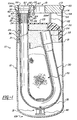
- Fig. 1 is a cross-sectional view of an accumulator having a deflector connection according to the present invention.
- Fig. 2 shows an expanded view of the accumulator of Fig. 1, detailing the assembly of the parts of the accumulator deflector connection according to the present invention.
- Fig. 3 is a perspective view of an outlet end of an outlet tube, detailing part of the deflector connection according to the preferred embodiment of the present invention.
- Fig. 4 is a perspective view of an outlet end of an outlet tube, detailing part of the deflector connection according to a first altemative embodiment of the present invention.
- Fig. 5 is a perspective view of an outlet end of an outlet tube, detailing part of the deflector connection according to a second alternative embodiment of the present invention.
- an accumulator generally indicated as 10, according to the present invention for use in an automotive air-conditioning system.
- the accumulator 10 is designed to be connected into an air-conditioning system including a compressor (not shown), a condenser (not shown) and an evaporator (not shown).
- the accumulator 10 has a first end 10a, a second end 10b, includes a housing composed of a can 12, a baffle or deflector 20, an outlet tube 30, an oil filter 40, a puck 50, a deflector connection 60 and a desiccant bag 70.
- the can 12 is preferably made from a light alloy material, such as aluminum, of a quality and grade appropriate for accumulators.
- the can 12 is manufactured using a deep draw process resulting in an open end 13.
- the second end 10b of the accumulator 10 is formed in the can 12 during the deep draw process.
- the first end 10a of the accumulator 10 is formed by the puck 50 of the present invention.
- the puck 50 can be manufactured using any known appropriate process, however, the puck is preferably manufactured using a machining process.
- the puck includes an inlet passage 51 and an outlet passage 52 which have an external inlet hose (not shown) and an external outlet hose (not shown) connected thereto, respectively, for connection to the air-conditioning system of the automobile.
- the outlet passage 52 includes a first counterbore 53 located on an inner side 54 of the puck 50 creating a stop or land 55, as more fully described below.
- the outlet passage 52 further includes a second counterbore 56 and a third counterbore 57 that are used by the external outlet hose that is connected to the puck 50.
- the machining of the first, second and third counterbores 53, 56 and 57, respectively, results in a hole 58 in the middle of the inlet passage 52.
- the puck 50 includes a reduced diameter portion 59 which is inserted in the open end 13 of the can 12.
- the puck 50 is connected to the can 12 using a M.I.G. welding process or other appropriate process for welding the can 12 to the puck 50 as is well known in the art.
- the welding process results in a weld 14 between the can 12 and the puck 50.
- the deflector 20 of the present invention has a general cup shape, upside down in Figs 1 and 2, and is preferably manufactured from a thermoplastic material such as nylon. However, it is possible to use a metal or alloy material.
- the deflector is located within the can 12 and includes radially spaced tab extensions 21 for maintaining the position of the deflector 20 within the housing of the accumulator 10.
- the deflector 20 further includes a vertical extension 22 extending from an upper surface 23 of the deflector 20.
- the vertical extension 22 has an end 22a which abuts the inner surface 54 of the puck 50 to help keep the deflector 20 in position and prevent vibration and movement of the deflector 20 during operation.
- the deflector 20 of the preferred embodiment includes a tab 24 which coacts with an inlet end 33 of the outlet tube to also help keep thc deflector 20 in place during operation.
- the tab 24 preferably has a relatively narrow width, which would be into the page in Fig. 1 and Fig. 2, as compared to the inlet end 33 of the outlet tube 30 to prevent blocking flow of the gaseous refrigerant fluid in the housing of the accumulator 10.
- the deflector 20 also includes a cylindrical extension 25 which is preferably integral and unitary with the deflector 20, the tabs 21, vertical extension 22, upper surface 23, and tab 24. It is also possible to have multiple vertical extension 22 balance and spaced from the cylindrical extension 50 of the deflector 20.
- the cylindrical extension 25 has a passage 26 which has the outlet end 32 of the outlet tube 30 located therein. The cylindrical extension 25 is located within and constitutes part of the connection 60 as described below.
- the outlet tube 30 of the present invention is formed as a "J" tube having a bight portion 31.
- the oil filter 40 of the accumulator 10 is located in a hole 35 located in the bottom of the bight portion 31 of the outlet tube 30 for entraining oil in the gaseous refrigerant fluid sent to the compressor.
- the outlet tube 30 further includes an anti-siphon hole 36 as is well known in the art.
- the outlet tube 30 includes knurling 34 which consists of lines formed in the outlet end 32 of the outlet tube 30.
- the knurling 34 is formed using any known process to create the lines altering the surface of the outlet end 32 of the outlet tube 30 sufficient to create areas into which the thermoplastic cylindrical extension 25 of the deflector 20 may flow when heated as described below.
- a tube 130 includes an end 132 and knurling 134.
- the tube 130 of the present embodiment differs in that a radial groove 138 is formed in the end 132 within the knurling 134.
- the radial groove 138 functions with the connection 60 as more fully described below.
- the radial groove 138 may be formed in the end 132 using any known process, however, it is preferable to use a rolling process for forming the radial groove 138.
- the tube 230 has and end 232 having knurling 234 which consists of criss-crossing lines.
- knurling 234 which consists of criss-crossing lines.
- the desiccant bag 70 is connected to the outlet tube 30 in any known manner.
- the desiccant bag 70 is connected within and near the bight portion 31 of the outlet tube 30 such that the desiccant bag 70 is carried by the outlet tube 30 and can be inserted within the can 12 of the housing of the accumulator 10 during manufacture.
- the oil filter 40 is connected to the bight portion 31 of the outlet tube 30 to siphon oil from the end 10b of the accumulator 10 for lubrication of the compressor, as is well known in the art.
- the connection 60 of the preferred embodiment includes a bushing 61 having a passage 64 located in the first counterbore 53 of the outlet passage 52, the cylindrical extension 25 of the deflector 20 located in the passage 64 of the bushing 61 and a reduced diameter or crimp 63 of the bushing 61.
- the bushing 61 is preferably inserted in the first counterbore 53 such that there is a low mechanical press fit such that the bushing 61 will not become removed from the counterbore 53.
- the connection between the puck 50 and the bushing 61 preferably is made more secure by spiking the puck around the outer periphery of the bushing 61 resulting in a spike mark 67 around the circumference of the bushing 61.
- the spiking of the bushing is preferably made using a similarly shaped tool having a leading edge designed to spike the material of the puck into the outer periphery of the bushing 61 during manufacture of the accumulator 10.
- connection 60 all of the sub parts of the accumulator 10 are connected to the puck 50, such that the only remaining step is to insert the outlet tube 30, oil filter 40, connection 60 and desiccant bag 70 into the can 12 and then weld the puck 50 into the open end 13 of the can 12 such that the reduced diameter portion 59 of the puck is located within the can 12.
- weld 14 can be made as described above, which creates a buildup of heat in the connection 60.
- the welding process can be controlled to create an appropriate amount of heat build up in the connection 60 such that the thermoplastic material of the deflector 20 is allowed to soften sufficiently to conform to the lines of the knurling 34 on the outlet end 32 of the outlet tube 30.
Landscapes
- Engineering & Computer Science (AREA)
- Chemical & Material Sciences (AREA)
- Analytical Chemistry (AREA)
- Power Engineering (AREA)
- Physics & Mathematics (AREA)
- Mechanical Engineering (AREA)
- Thermal Sciences (AREA)
- General Engineering & Computer Science (AREA)
- Air-Conditioning For Vehicles (AREA)
- Compressor (AREA)
- Supply Devices, Intensifiers, Converters, And Telemotors (AREA)
- Lining Or Joining Of Plastics Or The Like (AREA)
- Branch Pipes, Bends, And The Like (AREA)
- Injection Moulding Of Plastics Or The Like (AREA)
- Pressure Vessels And Lids Thereof (AREA)
- Transmission Of Braking Force In Braking Systems (AREA)
Applications Claiming Priority (2)
| Application Number | Priority Date | Filing Date | Title |
|---|---|---|---|
| US701174 | 1996-08-21 | ||
| US08/701,174 US5746065A (en) | 1996-08-21 | 1996-08-21 | Accumulator deflector connection and method |
Publications (2)
| Publication Number | Publication Date |
|---|---|
| EP0825399A1 true EP0825399A1 (fr) | 1998-02-25 |
| EP0825399B1 EP0825399B1 (fr) | 2001-06-27 |
Family
ID=24816347
Family Applications (1)
| Application Number | Title | Priority Date | Filing Date |
|---|---|---|---|
| EP97400922A Expired - Lifetime EP0825399B1 (fr) | 1996-08-21 | 1997-04-23 | Connexion entre accumulateur et déflecteur, et procédé de connexion |
Country Status (12)
| Country | Link |
|---|---|
| US (1) | US5746065A (fr) |
| EP (1) | EP0825399B1 (fr) |
| JP (1) | JPH1078274A (fr) |
| KR (1) | KR100232917B1 (fr) |
| CN (1) | CN1174316A (fr) |
| AR (1) | AR010989A1 (fr) |
| BR (1) | BR9703113A (fr) |
| CA (1) | CA2204694C (fr) |
| CZ (1) | CZ177297A3 (fr) |
| DE (1) | DE69705368T2 (fr) |
| ES (1) | ES2158463T3 (fr) |
| ZA (1) | ZA973046B (fr) |
Cited By (5)
| Publication number | Priority date | Publication date | Assignee | Title |
|---|---|---|---|---|
| EP1046872A3 (fr) * | 1999-04-20 | 2001-02-07 | Ti Group Automotive Systems Limited | Accumulateur à déshydration pour systémes frigorifiques |
| EP1353134A1 (fr) * | 2002-04-11 | 2003-10-15 | SKG Italiana S.P.A. | Accumulateur sécheur |
| EP1319909A3 (fr) * | 2001-12-14 | 2004-02-04 | Ti Automotive Cisliano S.r.l. | Accumulateur/dessicateur à structure simplifiée pour circuits frigorifiques |
| EP1607698A3 (fr) * | 2004-05-27 | 2006-10-25 | Tgk Company, Ltd. | Circuit de refrigeration |
| EP4488602A1 (fr) | 2023-07-07 | 2025-01-08 | Hutchinson Fluid Management Systems, Inc. | Accumulateur pour un circuit de climatisation |
Families Citing this family (20)
| Publication number | Priority date | Publication date | Assignee | Title |
|---|---|---|---|---|
| US6430958B1 (en) | 2001-01-22 | 2002-08-13 | Halla Climate Control Canada, Inc. | Suction accumulator for air conditioning systems |
| US6453697B1 (en) | 2001-04-23 | 2002-09-24 | Designed Metal Products, Inc. | Seal for vessel and method of forming same |
| US6463757B1 (en) | 2001-05-24 | 2002-10-15 | Halla Climate Controls Canada, Inc. | Internal heat exchanger accumulator |
| US6438972B1 (en) | 2001-08-29 | 2002-08-27 | Automotive Fluid Systems, Inc. | Vessel assembly and related manufacturing method |
| US6481241B1 (en) * | 2001-08-29 | 2002-11-19 | Automotive Fluid Systems, Inc. | Accumulator desiccant bag and method of assembling |
| US6568204B2 (en) * | 2001-10-30 | 2003-05-27 | Automotive Fluid Systems, Inc. | Baffle connection for an accumulator and related method of manufacturing |
| US6915646B2 (en) * | 2002-07-02 | 2005-07-12 | Delphi Technologies, Inc. | HVAC system with cooled dehydrator |
| DE10300802B4 (de) * | 2003-01-13 | 2007-10-11 | Hansa Metallwerke Ag | Akkumulator für eine Klimaanlage, insbesondere Fahrzeugklimaanlage |
| US20050081559A1 (en) * | 2003-10-20 | 2005-04-21 | Mcgregor Ian A.N. | Accumulator with pickup tube |
| US7461519B2 (en) | 2005-02-03 | 2008-12-09 | Halla Climate Control Canada, Inc. | Accumulator with deflector |
| DE102006022024A1 (de) * | 2006-05-10 | 2007-11-15 | Behr Gmbh & Co. Kg | Akkumulator, insbesondere für eine Kraftfahrzeug-Klimaanlage |
| KR100789709B1 (ko) * | 2006-12-13 | 2008-01-03 | 삼성전자주식회사 | 공조기기 |
| DE102007033149A1 (de) * | 2007-07-13 | 2009-01-15 | Behr Gmbh & Co. Kg | Akkumulator, insbesondere für eine Klimaanlage, mit Schmutzfänger |
| CN101398240B (zh) * | 2007-09-29 | 2011-01-19 | 浙江三花制冷集团有限公司 | 一种回油装置和气液分离器 |
| US9043243B2 (en) * | 2008-06-02 | 2015-05-26 | Apple Inc. | System and method of generating a media package for ingesting into an on-line downloading application |
| DE102008028852A1 (de) * | 2008-06-19 | 2009-12-24 | Behr Gmbh & Co. Kg | Kältemittelsammler mit Flüssigkeitsabscheider |
| KR101474819B1 (ko) * | 2011-11-23 | 2014-12-22 | 한라비스테온공조 주식회사 | 차량용 히트 펌프 시스템 |
| CN103307821B (zh) * | 2013-05-21 | 2015-09-16 | 浙江盾安冷链系统有限公司 | 一种气液分离器 |
| JP6173558B2 (ja) * | 2014-02-28 | 2017-08-02 | 三菱電機株式会社 | アキュムレータ及びこのアキュムレータを備えた冷凍装置 |
| JP6661345B2 (ja) * | 2015-07-14 | 2020-03-11 | 株式会社不二工機 | アキュームレータ |
Citations (7)
| Publication number | Priority date | Publication date | Assignee | Title |
|---|---|---|---|---|
| US3938353A (en) * | 1973-05-11 | 1976-02-17 | Virginia Chemicals, Inc. | Liquid trapping suction accumulator |
| US4651540A (en) * | 1986-03-21 | 1987-03-24 | Tecumseh Products Company | Suction accumulator including an entrance baffle |
| US4675971A (en) * | 1985-12-03 | 1987-06-30 | Michigan Special Products, Inc. | Desiccant assembly for refrigeration circuit and method |
| US4835986A (en) * | 1987-12-30 | 1989-06-06 | Carlisle Jr Billy M | Universal accumulator |
| US4994185A (en) * | 1989-03-23 | 1991-02-19 | Multiform Desiccants, Inc. | Combined heat shielding and bonding device for adsorbent packet in refrigerant receiver |
| US5191775A (en) * | 1988-10-31 | 1993-03-09 | Showa Aluminum Corporation | Refrigerant receiver |
| US5365751A (en) * | 1993-09-13 | 1994-11-22 | General Motors Corporation | Universal accumulator dehydrator assembly |
Family Cites Families (11)
| Publication number | Priority date | Publication date | Assignee | Title |
|---|---|---|---|---|
| US3754409A (en) * | 1972-03-06 | 1973-08-28 | Virginia Chemicals Inc | Liquid trapping suction accumulator |
| US4111005A (en) * | 1977-04-07 | 1978-09-05 | General Motors Corporation | Press-on plastic baffle for accumulator-dehydrator |
| US4627247A (en) * | 1986-03-21 | 1986-12-09 | Tecumseh Products Company | Suction accumulator |
| US4768355A (en) * | 1987-01-27 | 1988-09-06 | Ford Motor Company | Accumulator with refrigerant processing cartridge for automotive air conditioning system |
| US4800737A (en) * | 1987-04-17 | 1989-01-31 | Ford Motor Company | Automotive air conditioning system accumulator with refrigerant processing cartridge including evaporator pressure regulator |
| US5075967A (en) * | 1990-08-03 | 1991-12-31 | Bottum Edward W | Method of assembing a suction accumulator |
| US5184479A (en) * | 1991-12-23 | 1993-02-09 | Ford Motor Company | Accumulator for vehicle air conditioning system |
| US5184480A (en) * | 1991-12-23 | 1993-02-09 | Ford Motor Company | Accumulator for vehicle air conditioning system |
| US5245842A (en) * | 1992-05-01 | 1993-09-21 | Fayette Tubular Technology Corporation | Receiver dryer |
| US5479790A (en) * | 1993-07-06 | 1996-01-02 | Bottum, Jr.; Edward W. | Suction accumulator structure |
| US5507159A (en) * | 1994-04-25 | 1996-04-16 | Tecumseh Products Company | Suction accumulator vibration damper |
-
1996
- 1996-08-21 US US08/701,174 patent/US5746065A/en not_active Expired - Fee Related
-
1997
- 1997-04-10 ZA ZA9703046A patent/ZA973046B/xx unknown
- 1997-04-23 EP EP97400922A patent/EP0825399B1/fr not_active Expired - Lifetime
- 1997-04-23 DE DE69705368T patent/DE69705368T2/de not_active Expired - Fee Related
- 1997-04-23 ES ES97400922T patent/ES2158463T3/es not_active Expired - Lifetime
- 1997-05-07 CA CA002204694A patent/CA2204694C/fr not_active Expired - Fee Related
- 1997-05-09 BR BR9703113A patent/BR9703113A/pt not_active IP Right Cessation
- 1997-05-30 CN CN97105510A patent/CN1174316A/zh active Pending
- 1997-06-09 CZ CZ971772A patent/CZ177297A3/cs unknown
- 1997-07-18 KR KR1019970033410A patent/KR100232917B1/ko not_active Expired - Fee Related
- 1997-08-20 AR ARP970103778A patent/AR010989A1/es unknown
- 1997-08-21 JP JP9224678A patent/JPH1078274A/ja active Pending
Patent Citations (7)
| Publication number | Priority date | Publication date | Assignee | Title |
|---|---|---|---|---|
| US3938353A (en) * | 1973-05-11 | 1976-02-17 | Virginia Chemicals, Inc. | Liquid trapping suction accumulator |
| US4675971A (en) * | 1985-12-03 | 1987-06-30 | Michigan Special Products, Inc. | Desiccant assembly for refrigeration circuit and method |
| US4651540A (en) * | 1986-03-21 | 1987-03-24 | Tecumseh Products Company | Suction accumulator including an entrance baffle |
| US4835986A (en) * | 1987-12-30 | 1989-06-06 | Carlisle Jr Billy M | Universal accumulator |
| US5191775A (en) * | 1988-10-31 | 1993-03-09 | Showa Aluminum Corporation | Refrigerant receiver |
| US4994185A (en) * | 1989-03-23 | 1991-02-19 | Multiform Desiccants, Inc. | Combined heat shielding and bonding device for adsorbent packet in refrigerant receiver |
| US5365751A (en) * | 1993-09-13 | 1994-11-22 | General Motors Corporation | Universal accumulator dehydrator assembly |
Cited By (7)
| Publication number | Priority date | Publication date | Assignee | Title |
|---|---|---|---|---|
| EP1046872A3 (fr) * | 1999-04-20 | 2001-02-07 | Ti Group Automotive Systems Limited | Accumulateur à déshydration pour systémes frigorifiques |
| US6442965B1 (en) | 1999-04-20 | 2002-09-03 | Ti Group Automotive Systems Limited | Dehydrating accumulator for refrigeration systems |
| EP1319909A3 (fr) * | 2001-12-14 | 2004-02-04 | Ti Automotive Cisliano S.r.l. | Accumulateur/dessicateur à structure simplifiée pour circuits frigorifiques |
| EP1353134A1 (fr) * | 2002-04-11 | 2003-10-15 | SKG Italiana S.P.A. | Accumulateur sécheur |
| EP1607698A3 (fr) * | 2004-05-27 | 2006-10-25 | Tgk Company, Ltd. | Circuit de refrigeration |
| EP4488602A1 (fr) | 2023-07-07 | 2025-01-08 | Hutchinson Fluid Management Systems, Inc. | Accumulateur pour un circuit de climatisation |
| FR3150852A1 (fr) * | 2023-07-07 | 2025-01-10 | Hutchinson Fluid Management Systems, Inc. | Accumulateur pour un circuit de climatisation |
Also Published As
| Publication number | Publication date |
|---|---|
| DE69705368D1 (de) | 2001-08-02 |
| CA2204694A1 (fr) | 1998-02-21 |
| EP0825399B1 (fr) | 2001-06-27 |
| BR9703113A (pt) | 1998-09-01 |
| AR010989A1 (es) | 2000-08-02 |
| DE69705368T2 (de) | 2001-10-31 |
| ES2158463T3 (es) | 2001-09-01 |
| ZA973046B (en) | 1997-11-04 |
| KR100232917B1 (ko) | 1999-12-01 |
| CZ177297A3 (cs) | 1998-06-17 |
| CN1174316A (zh) | 1998-02-25 |
| CA2204694C (fr) | 2000-08-29 |
| KR19980018191A (ko) | 1998-06-05 |
| US5746065A (en) | 1998-05-05 |
| JPH1078274A (ja) | 1998-03-24 |
Similar Documents
| Publication | Publication Date | Title |
|---|---|---|
| EP0825399B1 (fr) | Connexion entre accumulateur et déflecteur, et procédé de connexion | |
| US4474035A (en) | Domed accumulator for automotive air conditioning system | |
| EP0916063B1 (fr) | Cartouche deshydratante et son procede de montage | |
| EP0713994B1 (fr) | Bloc de jonction avec inserts | |
| US4430868A (en) | Evaporator particularly suitable for air conditioners in automotive vehicles | |
| EP0800044A2 (fr) | Dessiccateur/accumulateur pour système de refroidissement et son procédé de fabrication | |
| US5749347A (en) | Fuel leakage prevention system having latch-engaged valve | |
| US5515696A (en) | Receiver/drier/filter assembly | |
| US5904055A (en) | Accumulator deflector having a plastic bushing | |
| US20080148768A1 (en) | Receiver tank for a condensor and method of manufacturing the same | |
| EP0142095A2 (fr) | Dispositif combiné d'accumulateur et de déshydrateur pour un système de conditionnement d'air | |
| EP0925816A1 (fr) | Filtre du type à montage par vessage et son procédé de fabrication | |
| US6062039A (en) | Universal accumulator for automobile air conditioning systems | |
| EP0704662B1 (fr) | Echangeur de chaleur à cartouche de filtre déshydrateur intégrale | |
| US6722155B2 (en) | Baffle connection for an accumulator and related method of manufacturing | |
| US20030080564A1 (en) | Pipe joint assembly and method for assembling the same | |
| KR20050084338A (ko) | 일체형 냉매 라인을 갖는 블록 밸브 | |
| US5970738A (en) | Accumulator oil filter/orifice having an extended tube | |
| US20010004010A1 (en) | Heat exchanger having snap-on bracket | |
| EP1584855B1 (fr) | Structure de raccordement de tuyau | |
| US20010040026A1 (en) | Heat exchanger having snap-on bracket | |
| EP1319908B1 (fr) | Echangeur thermique | |
| EP0669507B1 (fr) | Réservoir/Déshydrateur | |
| WO1998011396A1 (fr) | Deflecteur d'accumulateur a bague en matiere plastique | |
| EP1580500B1 (fr) | Cartouche filtrante pour système de climatisation de véhicule automobile |
Legal Events
| Date | Code | Title | Description |
|---|---|---|---|
| PUAI | Public reference made under article 153(3) epc to a published international application that has entered the european phase |
Free format text: ORIGINAL CODE: 0009012 |
|
| AK | Designated contracting states |
Kind code of ref document: A1 Designated state(s): DE ES FR GB IT |
|
| 17P | Request for examination filed |
Effective date: 19980702 |
|
| AKX | Designation fees paid |
Free format text: DE ES FR GB IT |
|
| RBV | Designated contracting states (corrected) |
Designated state(s): DE ES FR GB IT |
|
| GRAG | Despatch of communication of intention to grant |
Free format text: ORIGINAL CODE: EPIDOS AGRA |
|
| 17Q | First examination report despatched |
Effective date: 20000626 |
|
| GRAG | Despatch of communication of intention to grant |
Free format text: ORIGINAL CODE: EPIDOS AGRA |
|
| GRAH | Despatch of communication of intention to grant a patent |
Free format text: ORIGINAL CODE: EPIDOS IGRA |
|
| GRAH | Despatch of communication of intention to grant a patent |
Free format text: ORIGINAL CODE: EPIDOS IGRA |
|
| GRAA | (expected) grant |
Free format text: ORIGINAL CODE: 0009210 |
|
| AK | Designated contracting states |
Kind code of ref document: B1 Designated state(s): DE ES FR GB IT |
|
| REF | Corresponds to: |
Ref document number: 69705368 Country of ref document: DE Date of ref document: 20010802 |
|
| ET | Fr: translation filed | ||
| ITF | It: translation for a ep patent filed | ||
| REG | Reference to a national code |
Ref country code: ES Ref legal event code: FG2A Ref document number: 2158463 Country of ref document: ES Kind code of ref document: T3 |
|
| REG | Reference to a national code |
Ref country code: GB Ref legal event code: IF02 |
|
| PGFP | Annual fee paid to national office [announced via postgrant information from national office to epo] |
Ref country code: GB Payment date: 20020417 Year of fee payment: 6 Ref country code: ES Payment date: 20020417 Year of fee payment: 6 |
|
| PLBE | No opposition filed within time limit |
Free format text: ORIGINAL CODE: 0009261 |
|
| STAA | Information on the status of an ep patent application or granted ep patent |
Free format text: STATUS: NO OPPOSITION FILED WITHIN TIME LIMIT |
|
| 26N | No opposition filed | ||
| PG25 | Lapsed in a contracting state [announced via postgrant information from national office to epo] |
Ref country code: GB Free format text: LAPSE BECAUSE OF NON-PAYMENT OF DUE FEES Effective date: 20030423 |
|
| PG25 | Lapsed in a contracting state [announced via postgrant information from national office to epo] |
Ref country code: ES Free format text: LAPSE BECAUSE OF NON-PAYMENT OF DUE FEES Effective date: 20030424 |
|
| GBPC | Gb: european patent ceased through non-payment of renewal fee |
Effective date: 20030423 |
|
| REG | Reference to a national code |
Ref country code: ES Ref legal event code: FD2A Effective date: 20030424 |
|
| PG25 | Lapsed in a contracting state [announced via postgrant information from national office to epo] |
Ref country code: IT Free format text: LAPSE BECAUSE OF NON-PAYMENT OF DUE FEES;WARNING: LAPSES OF ITALIAN PATENTS WITH EFFECTIVE DATE BEFORE 2007 MAY HAVE OCCURRED AT ANY TIME BEFORE 2007. THE CORRECT EFFECTIVE DATE MAY BE DIFFERENT FROM THE ONE RECORDED. Effective date: 20050423 |
|
| PGFP | Annual fee paid to national office [announced via postgrant information from national office to epo] |
Ref country code: DE Payment date: 20080502 Year of fee payment: 12 |
|
| PGFP | Annual fee paid to national office [announced via postgrant information from national office to epo] |
Ref country code: FR Payment date: 20080414 Year of fee payment: 12 |
|
| REG | Reference to a national code |
Ref country code: FR Ref legal event code: ST Effective date: 20091231 |
|
| PG25 | Lapsed in a contracting state [announced via postgrant information from national office to epo] |
Ref country code: DE Free format text: LAPSE BECAUSE OF NON-PAYMENT OF DUE FEES Effective date: 20091103 |
|
| PG25 | Lapsed in a contracting state [announced via postgrant information from national office to epo] |
Ref country code: FR Free format text: LAPSE BECAUSE OF NON-PAYMENT OF DUE FEES Effective date: 20091222 |