EP0825581B1 - Unité mobile et système de soutien d'unités mobiles - Google Patents
Unité mobile et système de soutien d'unités mobiles Download PDFInfo
- Publication number
- EP0825581B1 EP0825581B1 EP97112721A EP97112721A EP0825581B1 EP 0825581 B1 EP0825581 B1 EP 0825581B1 EP 97112721 A EP97112721 A EP 97112721A EP 97112721 A EP97112721 A EP 97112721A EP 0825581 B1 EP0825581 B1 EP 0825581B1
- Authority
- EP
- European Patent Office
- Prior art keywords
- information
- mobile unit
- section
- unit
- receiving
- Prior art date
- Legal status (The legal status is an assumption and is not a legal conclusion. Google has not performed a legal analysis and makes no representation as to the accuracy of the status listed.)
- Expired - Lifetime
Links
Images














Classifications
-
- G—PHYSICS
- G08—SIGNALLING
- G08G—TRAFFIC CONTROL SYSTEMS
- G08G1/00—Traffic control systems for road vehicles
- G08G1/09—Arrangements for giving variable traffic instructions
- G08G1/0962—Arrangements for giving variable traffic instructions having an indicator mounted inside the vehicle, e.g. giving voice messages
- G08G1/0967—Systems involving transmission of highway information, e.g. weather, speed limits
- G08G1/096708—Systems involving transmission of highway information, e.g. weather, speed limits where the received information might be used to generate an automatic action on the vehicle control
- G08G1/096716—Systems involving transmission of highway information, e.g. weather, speed limits where the received information might be used to generate an automatic action on the vehicle control where the received information does not generate an automatic action on the vehicle control
-
- G—PHYSICS
- G08—SIGNALLING
- G08G—TRAFFIC CONTROL SYSTEMS
- G08G1/00—Traffic control systems for road vehicles
- G08G1/01—Detecting movement of traffic to be counted or controlled
- G08G1/0104—Measuring and analyzing of parameters relative to traffic conditions
-
- G—PHYSICS
- G08—SIGNALLING
- G08G—TRAFFIC CONTROL SYSTEMS
- G08G1/00—Traffic control systems for road vehicles
- G08G1/09—Arrangements for giving variable traffic instructions
-
- G—PHYSICS
- G08—SIGNALLING
- G08G—TRAFFIC CONTROL SYSTEMS
- G08G1/00—Traffic control systems for road vehicles
- G08G1/09—Arrangements for giving variable traffic instructions
- G08G1/0962—Arrangements for giving variable traffic instructions having an indicator mounted inside the vehicle, e.g. giving voice messages
- G08G1/0967—Systems involving transmission of highway information, e.g. weather, speed limits
- G08G1/096708—Systems involving transmission of highway information, e.g. weather, speed limits where the received information might be used to generate an automatic action on the vehicle control
- G08G1/096725—Systems involving transmission of highway information, e.g. weather, speed limits where the received information might be used to generate an automatic action on the vehicle control where the received information generates an automatic action on the vehicle control
-
- G—PHYSICS
- G08—SIGNALLING
- G08G—TRAFFIC CONTROL SYSTEMS
- G08G1/00—Traffic control systems for road vehicles
- G08G1/09—Arrangements for giving variable traffic instructions
- G08G1/0962—Arrangements for giving variable traffic instructions having an indicator mounted inside the vehicle, e.g. giving voice messages
- G08G1/0967—Systems involving transmission of highway information, e.g. weather, speed limits
- G08G1/096733—Systems involving transmission of highway information, e.g. weather, speed limits where a selection of the information might take place
- G08G1/09675—Systems involving transmission of highway information, e.g. weather, speed limits where a selection of the information might take place where a selection from the received information takes place in the vehicle
-
- G—PHYSICS
- G08—SIGNALLING
- G08G—TRAFFIC CONTROL SYSTEMS
- G08G1/00—Traffic control systems for road vehicles
- G08G1/09—Arrangements for giving variable traffic instructions
- G08G1/0962—Arrangements for giving variable traffic instructions having an indicator mounted inside the vehicle, e.g. giving voice messages
- G08G1/0967—Systems involving transmission of highway information, e.g. weather, speed limits
- G08G1/096766—Systems involving transmission of highway information, e.g. weather, speed limits where the system is characterised by the origin of the information transmission
- G08G1/096775—Systems involving transmission of highway information, e.g. weather, speed limits where the system is characterised by the origin of the information transmission where the origin of the information is a central station
Definitions
- the present invention relates to a mobile unit support system and a mobile unit, capable of transmitting information by transmitting and receiving signals between a plurality of modules installed at different positions.
- the use of a portable telephone or the like can realize the factors (4) and (5). Also, the radio or the like equipment permits acquisition of information on traffic congestion or the like.
- the factor (4) has no relation with the factors (1) to (3), and it seems that they can be processed independently of each other. If information to be communicated is of the type used with a navigator, however, the factor (4) may be related to the factors (1) to (3). It is not efficient, therefore, to realize the above-mentioned five factors independently of each other but an overall integrated system is desirably built up. By doing so, the road conditions can be accurately grasped, and the information used with the navigator can be generated based on the road conditions, thereby making it possible to supply information much more useful than the information obtained from a CD ROM or the like.
- a multiplicity of vehicles running on a road undesirably transmit a high-output radio wave.
- the conventional method of producing information on traffic congestion or the like has the problem that since the number and places of installation of automotive vehicle detection units are limited, the movement conditions of individual automotive vehicles cannot be grasped, and therefore it is impossible to acquire detailed road situations including accidents and traffic congestion. For this reason, the road situations within a small area can be known only in a range visible by eyes, thereby making it impossible to know the road situations out of sight.
- RACS road automobile communication system
- the RACS offers a road automobile communication function within a minimum radio zone using beacon stations connected to a wire transmission line, thus constituting a wide area network.
- the beacon stations transmit data to automobiles and receive data therefrom.
- Each such beacon station is connected with a control centre by a so-called cable transmission line.
- a static information beacon that offers fixed information, such as the position and road signs
- a dynamic information beacon that offers changing information, such as concerning traffic conditions and an individual communication beacon capable of a two-way communication function.
- the object of the present invention is to provide a mobile unit support system capable of grasping the movement conditions of individual mobile units and producing detailed road situations.
- (a) is a diagram showing an example of a transmission system according to the first embodiment, and (b) is a diagram for explaining the operation of the same system.
- a transmission system will be explained first with reference to Fig. 1 providing a diagram showing a configuration of a module used in the particular system.
- a receiving section 13 of a module 11 is a receiving unit for receiving an input signal 12 in accordance with a predetermined radio scheme.
- a transmission section 14 is a transmission unit for transmitting an output signal 15 in accordance with a predetermined radio scheme based on the input signal 12 received by the receiving section 13.
- the predetermined radio scheme is defined as a scheme for radio communication using radio wave, light (infrared ray, etc.), laser, sound wave or ultrasonic wave.
- the receiving section 13 is a receiving unit configured of a receiving circuit connected with a receiving antenna (receiving-end conversion section)
- the transmission section 14 is a transmission unit configured of a transmission circuit connected with a transmission antenna (transmitting-end conversion section).
- the receiving section 13 is a receiving unit configured of a receiving circuit connected with a photo-electric conversion circuit (receiving-end conversion section), and the transmission section 14 is a transmission unit configured of a transmission circuit connected with an electro-optic conversion circuit (transmitting-end conversion section).
- the receiving section 13 is a receiving unit configured of a receiving circuit connected with a microphone or a sound collector (receiving-end conversion section)
- the transmission section 14 is a transmission unit configured of a transmission circuit connected with a speaker (transmitting-endconversion section). In short,.
- the only difference lies in the receiving-end or the transmitting-end conversion section for converting radio wave, light (infrared ray or the like), laser, sound or ultrasonic wave into electric energy or converting electric energy into radio wave, light (infrared ray or the like), laser, sound wave or ultrasonic wave, respectively, whereas the associated receiving circuit or the associated transmission circuit, as the case may be, is configured based on a common operation mode.
- a configuration of a transmission system according to this embodiment will be explained with reference to Fig. 2(a) making up a diagram showing an example thereof.
- a transmission system according to this embodiment is configured by installing a plurality of modules 11 in spaced relation with each other along a center line 17 of a one-lane road 16.
- the transmission section 14 transmits an i-th output signal 15 based on the i-th input signal 12 received from the receiving section 13 in accordance with a predetermined radio scheme. Specifically, the transmission section 14 transmits an i-th output signal 15 containing the information contained in the i-th input signal 12.
- the receiving section 13 receives the i-th output signal 15 transmitted from the transmission section 14 of the i-th module 11 as the (i+1)th input signal 12 in accordance with a predetermined radio scheme.
- the transmission section 14 transmits the (i+1)th output signal 15 containing the information contained in the (i+1)th input signal 12 received by the receiving section 13 in accordance with a predetermined radio scheme.
- n modules 11 an integer of 2 or more
- i is assumed to be an integer satisfying the relation 1 ⁇ i ⁇ n.
- the receiving section 13 and the transmission section 14 of each of the plurality of the modules 11 installed along a road receive the input signal 12 and transmit the output signal 15, respectively, in accordance with a predetermined radio scheme, thereby making it possible to transmit the information contained in the particular signals along the particular road.
- the invention is not necessarily limited to this configuration, but the modules can alternatively be installed along either end of the one-lane road 16.
- the modules 11 can be installed along such a guard rail.
- the plurality of the modules 11 can be installed in such a manner that the information transmitted transverse a plurality of lanes. In short, each of the plurality of the modules can be installed at a different position on a road.
- each output signal 15 is transmitted to a destination along a road by transmitting each output signal 15 to an adjacent module 11 according to this embodiment
- the invention is not necessarily limited to such a configuration.
- the signal can be transmitted, for example, from the i-th module 11 to the (i-1)th module 11, from the (i-1)th module 11 to the (i+2)th module 11, from the (i+2)th module 11 to the (i+1)th module 11, and from the (i+1)th module to the (i+4)th module, so that the information contained in the signal may be transmitted along the road.
- each of the plurality of the modules is adapted to receive and transmit a signal thereby to transmit the information contained in the signal by relay along the whole or part of the road.
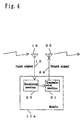
- a receiving antenna 18 is a receiving antenna for catching a radio wave radiated into space and arriving as electric power.
- a receiving section 20 is a radio receiving circuit for receiving as an input signal 19 a modulated high-frequency current making up a high-frequency current of a predetermined frequency (hereinafter called also a carrier frequency) modulated by a signal wave current containing the information to be transmitted, and demodulating the signal wave current from the particular input signal 19.
- the receiving circuit 20 or the transmission section 21 described later can include an amplifier circuit (not shown) for amplifying the signal wave current with a predetermined amplification factor.
- the transmission section 21 is a radio transmission circuit in which a high-frequency current having the same frequency as said predetermined frequency is modulated by the signal wave current demodulated by the receiving section 20 thereby to generate a modulated high-frequency current (output signal 22).
- the transmission antenna 23 is an antenna for radiating a radio wave into space by the output signal 22 generated by the transmission section 21.
- a transmission system is configured by installing a plurality of modules 11a in spaced relationship with each other along a predetermined route.
- the predetermined route may be a road (roadway or walkway), a corridor in a building, a route in a factor, a railway, a route in a parking lot, a route in a room, a route in a warehouse, a course of a ship, a route in an airport or the like.
- the radio wave arriving by being caught as an input signal 19 by the receiving antenna 18 corresponds to the input signal or the first input signal received by the receiving means or the first receiving means, respectively, of each module in a transmission system according to this invention.
- the radio wave radiated into space from the transmission antenna 23 corresponds to the output signal or the first output signal transmitted by the transmission means or the first transmission means, respectively, according to the present invention.
- the receiving antenna 18 and the receiving means 20 correspond to the receiving means or the first receiving means according to the invention, while the transmission section 21 and the transmission antenna 23 correspond to the transmission means or the first transmission means according to the present invention.
- Fig. 5 constituting a diagram for explaining the operation of a transmission system according to this embodiment.
- the receiving antenna 18 catches the arriving radio wave radiated into spaced as electric power.
- the receiving section 20 receives as an i-th input signal 19 a modulated high-frequency current which is a high-frequency current of a predetermined frequency modulated by a signal wave current containing the . information to be transmitted, from the power caught by the receiving antenna 18.
- the i-th module 11a receives the radio wave arriving thereat out of all the radio waves radiated from the transmission antenna 23 of the (i-1)th module 11a by the (i-1)th output signal 22.
- the receiving section 20 demodulates the signal wave current from the i-th input signal 19.
- the transmission section 21 generates a modulated high-frequency current (i-th output signal 22) in such a manner that the high-frequency current having the same frequency as the predetermined frequency of the high-frequency current contained in the i-th input signal is modulated by the signal wave current demodulated by the receiving section 20.
- the transmission antenna 23 radiates a radio wave into space by the i-th output signal.22.
- the radio wave output radiated from the transmission antenna 23 of each of the plurality of the modules 11a is the output.caught only by the receiving antenna 18 of another module 11a adjacent thereto.
- each of the plurality of the modules 11a is installed in spaced relation along a predetermined route in such a manner that the radio wave radiated from the transmission antenna 23 may be received only by an adjacent one module.
- the receiving antenna 18 is located on the side at which the transmitted information arrives, and the transmission antenna 23 is located on the side from which the information is transmitted.
- the receiving antenna 18 and the transmission antenna 23 are in predetermined spaced relation with each other.
- the predetermined distance of space is set on the basis of the radio wave output radiated from the transmission antenna 23 and the inter-module distance.
- the range in which the radio waves radiated from the transmission antennas 23 of the (i-1)th, i-th and (i+1)th modules 11a can be received is limited to the (i-1)th, i-th and (i+1)th transmission areas 24, respectively.
- the radio wave radiated from the transmission antenna 23 of the i-th module 11a is caught only by the receiving antenna 18 of the (i+1)th module 11a.
- the receiving antenna 18 catches the arriving radio wave radiated into space as electric power.
- the receiving section 20 receives a modulated high-frequency current as the (i+1)th input signal 19 which is a high-frequency current of a predetermined frequency modulated by a signal wave current containing the information to be transmitted, from the electric power caught by the receiving antenna 18.
- the (i+1)th module 11a receives the radio wave arriving at the (i+1)th module 11a from among all the radio waves radiated from the transmission antenna 23 belonging to the i-th module 11a.
- the receiving section 20 demodulates the signal wave current from the (i+1)th input signal 19.
- the transmission section 21 generates a modulated high-frequency current ((i+1)th output signal 22) in such a manner that a high-frequency current having the same frequency as the predetermined frequency of the high-frequency current contained in the (i+1)th input signal 19 is modulated by the signal wave current demodulated by the receiving section 20.
- the transmission antenna 23 radiates a radio wave into space by the (i+1)th output signal 22.
- n an integer not less than 2
- i is assumed to be an integer satisfying the relation 1 ⁇ i ⁇ n.
- the receiving section 20 and the transmission section 21 belonging to each of the plurality of the modules 11a installed along a predetermined route receives the input signal 19 and transmits-the output signal 22, respectively, in accordance with a radio wave communication scheme, thereby making it possible to transmit the information contained in the particular signals along the particular predetermined route.
- radio wave communication scheme is used as a radio scheme according to this embodiment
- the invention is not necessarily limited to such a scheme, but can employ a radio scheme using light, laser, sound wave or ultrasonic wave.
- a photo-electric conversion circuit for catching the arriving light or laser as electric energy is used in place of the receiving antenna 18, and an electro-optic conversion circuit for emitting light or laser into space by an output signal is used in place of the transmission antenna 23.
- the receiving section extracts the information from the electric energy caught by the photo-electric conversion circuit, and the transmission section generates an output signal containing the information extracted by the receiving section and applies the output signal thus generated to the electro-optic conversion circuit.
- a microphone or a sound collector for catching the arriving sound wave or ultrasonic wave as electric energy is used in place of the receiving antenna 18, and a speaker for transmitting sound wave or ultrasonic wave into space by an output signal is used in place of the transmission antenna 23.
- the receiving section extracts the information from the electric energy caught by the microphone or the sound collector, while the transmission section generates an output signal containing the information extracted by the receiving section and applies the output signal thus generated to the speaker.
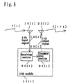
- a transmission system according to a third embodiment of the present invention will be explained with reference to Fig. 6 constituting a diagram showing a configuration of a module used in the system.
- a module 11[i] is used among i types of modules 11[i], where i is an integer not less than 2.
- a receiving antenna 18[i] is for catching the arriving radio wave radiated into space as electric power.
- a receiving section 20[i] is a radio receiving circuit for receiving, as an i-th input signal 19[i], a modulated high-frequency current which is a high-frequency current having a frequency f[i] modulated by a signal wave current containing the information to be transmitted, from the electric power caught by the receiving antenna 18[i], and for demodulating the signal wave current from the i-th input signal 19[i].
- the receiving section 20[i] or the transmission section 21[i] described later can include an amplifier circuit (not shown) for amplifying the signal wave current with a predetermined amplification factor.
- the transmission section 21[i] is a radio. transmission circuit for modulating a high-frequency current having a frequency f[i+1] different from f[i] by a signal wave current demodulated by the receiving section 20[i], and for generating a modulated high-frequency current (i-th output signal 22[i]).
- the transmission antenna 23[i] is for radiating a radio wave having a carrier frequency f[i+1] by the i-th output signal 22[i].
- the arriving radio wave caught as the input signal 19[i] by the receiving antenna 18[i] corresponds to the input signal or the first input signal received by the receiving means or the first receiving means, respectively, belonging to each module of a transmission system according to the present invention.
- the radio wave radiated into space from the transmission antenna 23[i] corresponds to the output signal or the first output signal transmitted by the transmission means or the first transmission means, respectively, according to the invention.
- the receiving antenna 18[i] and the receiving section 19[i] correspond to the receiving means or the first receiving means, respectively, according to the invention, while the transmission section 21[i] and the transmission antenna 23[i] correspond to the transmission means or the first transmission means, respectively, according to the present invention.
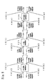
- n modules including a first module, a second module, a third module,...., a j-th module,...., a n-th module are installed in that order along a predetermined route, where j and n are integers and the predetermined route can be similar to the corresponding one in the transmission system according to the second embodiment of the invention.
- the radio wave radiated from the transmission antenna of each of the n modules is a radio wave of an output that can be received by up to the second module before and behind the module having the transmission antenna radiating the particular radio wave.
- the radio wave radiated from the transmission antenna 23[j] belong to the j-th module 11[j] can be received only by the modules 11[j-2], 11[j-1], 11[j+1] and 11[j+2].
- the carrier frequency f[1] of the radio wave caught by the receiving antenna 18[1] belonging to the first module 11[1] installed at an end of the i types of modules is equalized to the carrier frequency f[i+1] of the radio wave radiated from the transmission antenna 23[i] belonging to the i-th module 11[i] installed at the other end of the i types of modules, then, by installing a plurality of groups each including the i types of modules along a predetermined route of the desired length, information can be transmitted along the particular predetermined route.
- the present embodiment uses a radio wave communication scheme as a radio scheme
- the invention is not necessarily confined to such a scheme, but can employ a radio scheme using light, laser, sound wave or ultrasonic wave with equal effect.
- an optical demultiplexer for catching the light or laser of wavelength ⁇ [i] and converting it into electrical energy can be used instead of the receiving antenna 18[i], and a light source for emitting light or laser of wavelength ⁇ [i+1] by an output signal can be used in place of the transmission antenna 23[i].
- the receiving section extracts the information from the electric energy converted by the optical demultiplexer, while the transmission section generates an output signal containing the information extracted by the receiving section and applies the output signal thus generated to the light source thereof.
- an O/E converter for catching the light or laser of wavelength ⁇ and converting it into electrical energy can be used in place of the receiving antenna 18[i], and an E/O converter for converting the output signal into the light or laser of wavelength ⁇ in place of the transmission antenna 23[i].
- the receiving section extracts a modulated signal which is a signal of frequency f[i] modulated by a signal containing the information to be transmitted, from the electric energy converted by the O/E converter, and demodulates from the demodulated signal a signal containing the information to be transmitted.
- the transmission section modulates the signal of frequency f[i+1] with the signal demodulated by the receiving section and containing the information to be transmitted, and applies the particular demodulated signal as an output signal to the above-mentioned E/O converter.
- the receiving section extracts a demodulated signal which is an analog signal of an audio frequency band centered around the frequency f[i] modulated by a signal containing the information to be transmitted, from the electric energy caught by the microphone or the sound collector, and demodulates the signal containing the information to be transmitted.
- the transmission section modulates the analog signal of the audio frequency band centered around the frequency f[i+1] with the signal demodulated by the receiving section, and applies the modulated signal as an output signal to the speaker.
- a transmission system will be explained first with reference to Fig. 8 constituting a diagram showing a configuration of a module used with the system.
- a receiving section 13a belonging to a module 11b is a receiving unit for receiving two types of input signals 12[1], 12[2] in accordance with a predetermined radio scheme.
- the predetermined radio scheme can be similar to the predetermined radio scheme used with the transmission system according to the first embodiment of the invention.
- the transmission section 14a is a transmission unit for transmitting two types of output signals 15[1], 15[2] in accordance with a predetermined radio scheme on the basis of the two types of input signals 12[1], 12[2] received by the receiving section 13a.
- a transmission system is configured by installing a plurality of modules 11b in spaced relationship with each other along a predetermined route.
- the predetermined route can be similar to the counterpart of the transmission system according to the second embodiment of the invention.
- a receiving section 13a receives the (i-1)th output signal as an i-th input signal 12[1] transmitted from a transmission section 14a belonging to the (i-1)th module 11b in accordance with a predetermined radio scheme. Also, the receiving section 13a receives the (i+1)th output signal 15[2] as an i-th input signal 12[2] transmitted from a transmission section 14a belonging to the (i+1)th module 11b in accordance with a predetermined radio scheme.
- the transmission section 14a transmits the i-th output signal 15[1] containing the information contained in the i-th input signal 12[1] received by the receiving section 13a in accordance with a predetermined radio scheme. Also, the transmission section 14a transmits the i-th output signal 15[2] containing the information contained in the i-th input signal 12[2] received by the receiving section 13a in accordance with a predetermined radio scheme.
- the receiving section 13a receives the i-th output signal 15[1] as the (i+1)th input signal 12[1] transmitted from a transmission section 14a belonging to the i-th module 11b in accordance with a predetermined radio scheme. Also, the receiving section 13a receives the (i+2)th output signal 15[2] (not shown) as the (i+1)th input signal 12[2] transmitted from the transmission section 14a belonging to the (i+2)th module 11b in accordance with a predetermined radio scheme.
- the transmission section 14a transmits the (i+1)th output signal 15[1] containing the information contained in the (i+1)th input signal 12[1] received by the receiving section 13a thereof in accordance with a predetermined radio scheme. Also, the transmission section 14a transmits the (i+1)th output signal 15[2] containing the information contained in the (i+1)th input signal 12[2] received by the receiving section 13a in accordance with a predetermined radio scheme.
- the receiving section 13a and the transmission section 14a belonging to each of the plurality of the modules 11b installed along a predetermined route receive the input signals 12[1], 12[2] and transmit the output signals 15[1], 15[2], respectively, in accordance with a predetermined radio scheme, so that the information contained in the particular signals can be transmitted bidirectionally along the predetermined route.
- each of the plurality of the modules 11b includes the the receiving section 13a for receiving the two types of the input signals 12[1], 12[2] and the transmission section 14a for transmitting the two types of the output signals 15[1], 15[2].
- the invention is not necessarily confined to such a configuration.
- each of the plurality of the modules can include a receiving section for receiving i types of input signals 12[1],....,12[i] (i: natural number) and a transmission section for transmitting j types of output signals 15[1],...., 15[j] (j: natural number) on the basis of the i types of the input.signals 12[1],....,12[i] received by the receiving section.
- the.receiving means belonging to each of the plurality of the modules in a transmission system receives, as input signals thereto, the output signal transmitted from the transmission means belonging to another module adjacent thereto having the particular receiving means, and the output signal transmitted from the transmission means belonging to at least still another module adjacent thereto and different from said another module.
- the transmission means belonging to each of the plurality of the modules transmits an output signal in such a manner as to be received by the receiving means belonging to at least still another module adjacent to the first module having the first receiving means and different from the module having the transmission means that has transmitted the output signal received as an input signal by the receiving means belonging to the first module.
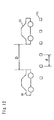
- a transmission system according to a fifth embodiment of the invention will be explained with reference to Fig. 10 providing a diagram showing a configuration of a part of the system.
- a first receiving section 25 is a receiving unit for receiving a first input signal 26 in accordance with a predetermined radio scheme.
- the predetermined radio scheme may be similar to the predetermined radio scheme used in the transmission system according to the first embodiment of the invention.
- a second transmission section 27 is a transmission unit for transmitting a second output signal 28 in accordance with a predetermined radio scheme on the basis of the first input signal received by the first receiving section 25.
- a second receiving section 29 is a receiving unit for receiving a second input signal 30 in accordance with a predetermined radio scheme.
- a first transmission section 31 is a transmission unit for transmitting a first output signal 32 in accordance with a predetermined radio scheme on the basis of the first input signal received by the first receiving section 25 and the second input signal 30 received by the second receiving section 29.
- the mobile unit 33 is an automotive vehicle.
- a receiving section 34 is a receiving unit for receiving a second output signal 28 as an input signal 35 transmitted from the second transmission section 27 belonging to the module 11c in accordance with a predetermined radio scheme.
- a transmission section 36 is a transmission unit for transmitting an output signal 37 containing the information to be transmitted in accordance with a predetermined radio scheme.
- the output signal 37 is received as the second input signal 30 by the second'receiving section 29 belonging to the module 11c.
- a transmission system like that of the first embodiment of the invention, is configured of a plurality of the modules 11c installed in spaced relationship with each other along a road.
- the length of the mobile unit 33 along the direction of movement thereof be L
- the distance between adjacent ones of the plurality of the modules 11c be d.
- the plurality of the modules 11c are installed along the road in such a manner as to satisfy the relation L > d.
- each of the plurality of the modules 11c is installed with an equal distance d apart from each other along the road in such a manner that at least one of the modules 11c is located within the length of the mobile unit 33 along the direction of movement thereof.
- the first receiving section 25 receives a first output signal 32 (not shown) as a first input signal 26 transmitted from a first transmission section 31 belonging to another module 11c adjacent to the transmitting end in accordance with a predetermined radio scheme.
- a second transmission section 27 transmits a second output signal 28 in accordance with a predetermined radio scheme on the basis of the first input signal 26 received by the first receiving section 25.
- the second transmission section 27 transmits the second output signal 28 containing the entire information contained in the first input signal 26 received by the first receiving section 25.
- the second receiving section 29 receives the second input signal 30 in accordance with a predetermined radio scheme.
- the first transmission section 31 transmits in accordance with a predetermined radio scheme the first output signal 32 containing the information contained in the first input signal 26 received by the first receiving section 25 and/or the information contained in the second input signal 30 received by the second receiving section 29. .
- the first output signal 32 is received as the first input signal 26 by the first receiving section 25 belonging to still another module 11c (not shown) adjacent to the transmitting end.
- a receiving section 34 receives the second output signal 28 as an input signal 35 transmitted from the second transmission section 27 belonging to the module 11c. By doing so, the mobile unit 33 can receive the information transmitted along the road.
- the transmission section 36 belonging to the mobile unit 33 transmits an output signal 37 containing the particular information to be transmitted in accordance with a predetermined radio scheme.
- This output signal 37 is received as the second input signal 30 by the second receiving section 29 belonging to the module 11c.
- the information to be transmitted is transmitted along the particular route as the necessary information.
- each of the plurality of the modules 11c installed along a road transfers the information transferred from another module 11c to still another module 11c.
- the particular information can be transmitted along the road, while at the same time making it possible to transmit along the same road the information received from the moving mobile unit 33. Further, the information transmitted along the road can be retransmitted to the mobile unit 33.
- the operation of the first receiving section 25 and the first transmission section 31 belonging to a module 11c with respect to another module 11c may be similar to the operation of the receiving means (the receiving section 13 in Fig. 1, the receiving antenna 18 and the receiving section 20 in Fig. 4, the receiving antenna 18[i] and the receiving section 20[i] in Fig. 6 or the receiving section 13a in Fig. 8) and the transmission means (the transmission section 14 in Fig. 1, the transmission section 21 and the transmission antenna 23 in Fig. 4, the transmission section 21[i] and the transmission antenna 23[i] in Fig. 6, or the transmission section 14b in Fig. 8), respectively, in the first to fourth embodiments.
- the receiving means the receiving section 13 in Fig. 1, the receiving antenna 18 and the receiving section 20 in Fig. 4, the receiving antenna 18[i] and the receiving section 20[i] in Fig. 6 or the receiving section 13a in Fig. 8
- the transmission means the transmission section 14 in Fig. 1, the transmission section 21 and the transmission antenna 23 in Fig. 4, the transmission section
- the mobile unit 33 equipped with the receiving section 34 and the transmission section 36 is an automotive vehicle
- the invention is not necessarily limited to it, but is equally applicable to a person having a portable telephone, an automatic cart in a factory, a train, a ship or an airplane.
- the invention is applicable to any mobile unit comprising the receiving section 34 and the transmission section 36.
- the plurality of the modules 11c are installed along a road according to the present embodiment, they may alternatively be installed along a predetermined route as in the transmission system according to the second embodiment of the invention.
- each of the plurality of the modules 11c can alternatively be installed in a manner to satisfy the relation D > d where D is the minimum following distance between the automotive vehicles running automatically as shown in Fig. 12.
- the second transmission section 27 transmits the second output signal 28 containing the entire information contained in the first input signal 26 received by the first receiving section 25 according to the present embodiment
- the invention is not necessarily limited to such a case,. but is equally applicable to a case in which the module 11c further includes an extraction section (not shown) for extracting the information on the mobile unit 33 from the information contained in the first input signal received by the first receiving section 25, so that the second transmission section 27 may transmit the second output signal 28 containing the information extracted by the extraction section.
- the second transmission section 27 can transmit the second output signal 28 containing the whole or part of the information contained in the first input signal 26 received by the first receiving section 25.
- first receiving section 25 and the second receiving section 29 can share a receiving unit of a common design.
- first transmission section 31 and the.second transmission section 27 may share a transmission unit of a common design.
- the output of the radio wave radiated from each module can be set with a margin, and also the design accuracy of each module can have a margin. Further, a longer processing time can be set for each module.
- information can be transmitted along a plurality of routes.
- information can be transmitted bidirectionally along a predetermined route.
- information can be transmitted along a predetermined route, while at the same time making it also possible to transmit along said route the information received from a mobile unit moving along said route. Further, it becomes possible to transmit to the mobile unit the information transmitted along said route.
- a transmission system using a module alternating between transfer and communication with a period including a plurality of transfer time zones and a specific or a common communication time zone, information can be transmitted along a predetermined route, while at the same time making it possible also to transmit along the particular route the information received from a mobile unit moving along the same route. Further, it becomes possible to transmit to the mobile unit the information transmitted along the route.
- a transmission system having a period including a specific communication time zone for transmitting and receiving signals in accordance with a radio wave communication scheme no interference occurs even in the case where each of'a plurality of modules communicates with a mobile unit using a radio wave of . a predetermined carrier frequency and where another adjacent module transmits and receives information with a mobile unit using a radio wave of the same carrier frequency.
- the information with the priority information added thereto can be transmitted and received in the order of priority.
- the information with the priority information for emergency application added thereto is processed in top priority and can be transmitted in priority even when the line is congested.
- a directional antenna for communication between a mobile unit and a module
- the communication between the mobile unit and the module can be set to one-to-one relation easily.
- the radio wave output is adjusted, the carrier frequencies of the radio waves transmitted and received in the plurality of the modules can be equalized. Further, the carrier frequency of the radio wave used for transmission and receiving between the modules can be equalized with the carrier frequency of the radio wave used for communication between a module and a mobile unit.
- the transmission of unnecessary information already received can be eliminated, thereby optimizing the conditions of transmission between modules. Also, even in the case where a response is required to the information transmitted from a mobile unit, the responding party can respond with the mobile unit identifier added to the information.
- the conditions of a predetermined route . can be accurately grasped by collecting the mobile unit detection information.
- each mobile unit moving along a predetermined route installed with a plurality of modules can measure the speed of another mobile unit and can measure the following distance at the same time based on the mobile unit detection information.
- Fig. 13 is a diagram showing a configuration of a mobile unit support system according to a 6th embodiment of the present invention.
- This mobile unit support system is configured of a mobile unit 301 represented by an automotive vehicle or the like running along a road as a route of movement, a detection source 302 including a plurality of objects to be detected installed in the direction in which the mobile unit 301 is driven on the road, and an information collection unit 303 for receiving the transmission signal from the mobile unit 301 and collecting information on the mobile unit 301 and the like.
- the mobile unit 301 is configured of a detection section 311 for detecting the detection source 302, an arithmetic processing section 312 for determining the information such as the velocity of the mobile unit and the position thereof on the road, for example, using the arrangement information such as the intervals and positions of the detection sources 302 stored in advance in a storage section (not shown) built therein on the basis of the detection signal from the detection section 311, and a transmission section 313 and a transmission antenna 34 for transmitting the output information of the arithmetic processing section 312 to the information collection unit 303.
- the information collection unit 303 is configured of a receiving antenna 333 and a receiving section 332 for receiving the transmission signal from the mobile unit 301 and a movement information processing section 331 for acquiring the moving conditions of the mobile unit 301 from the signal thus received.
- the types of energy applicable for a combination of the detection section 311 and the detection source 302 may include the magnetic field, radio wave, light, heat, sound wave, atmospheric pressure and the like.
- a permanent magnet is used as the detection source 302, thus eliminating the need of a drive source, and hence substantially no maintenance is required.
- the detection sources 302 can be arranged at intervals of, say, about a meter.
- the operation of detecting the detection sources 302 by the detection section 311 of the mobile unit 301 proceeds from left to right in the drawing, and the detection signal is output to the arithmetic processing section 312.
- the arithmetic processing section 312 arithmetically processes the detection signal input thereto with reference to the arrangement information of the detection sources 302 stored in advance in the storage section (not shown) such as a memory. This arithmetic processing is such that if the intervals at which the detection sources 302 are arranged is known, for example, the running speed of the mobile unit 301 can be calculated by measuring the temporal intervals of detection.
- the present position of the mobile unit 301 can be determined from the position information of the detection sources 302. Then, the mobile unit 301 transmits the information such as the velocity thus obtained through the transmission antenna 314 from the transmission section 313 using a radio wave to the information collection unit 303.
- the information collection unit 303 receives the radio wave transmitted from the mobile unit 301 by the receiving antenna 333 and the receiving section 332 and processes the received signal in the movement information processing section 331.
- the moving speed, the present position and the like information of the mobile unit 301 are extracted and the conditions of the mobile unit on the road are grasped, for example.
- the distance between the mobile units can be calculated by the mobile unit 301 or by the information collection unit 303 on the basis of the mobile detection information obtained by measuring the temporal intervals of mobile unit detection.
- the very information on mobile unit detection is transmitted to the information collection unit 303 from the mobile unit 303.
- Fig. 14 is a diagram showing a configuration of a mobile unit support system according to a 7th embodiment of the invention.
- This embodiment is different from the configuration of Fig. 13 in that in this embodiment, an information supply unit 304 is provided in place of the information collection unit 303, in that the mobile unit 301 includes a receiving section 315 and a receiving antenna 316 for receiving the signal from the information supply unit 304 in place of the transmission section 313 and the transmission antenna 314, and in that the arithmetic processing section 312 lacks the arrangement information of the detection sources 302.
- the information supply unit 304 is configured of a mobile unit information source 341 having information on the arrangement of the detection sources 341 and a transmission section 342 and a transmission antenna 343 for transmitting the information from the mobile unit information source 341 to the mobile unit 301, for example.
- the mobile unit 301 can determine the moving speed and the present position thereof on its own using the information on the arrangement of the detection sources 302 and the like transmitted from the information supply unit 304.
- Fig. 15 is a diagram showing a configuration of a mobile unit support system according to a 8th embodiment of the invention. This embodiment is different from the configuration of Fig. 13 shown above in that in this embodiment, the information collection unit 303 is lacking, the mobile unit 301 lacks the transmission section 313 and the transmission antenna 314, and that a display section 317 is provided for displaying the information obtained by the arithmetic processing section 312.
- the arithmetic processing section 312 causes the information such as the moving speed and the present position of the mobile unit 301 itself obtained in the same manner as in the 6th embodiment described above to be displayed on the display section 317.
- Fig. 16 is a diagram showing a configuration of a mobile unit support system according to a 9th embodiment of the invention. This embodiment is a combination of the configuration of Fig. 13 and that of Fig. 15.
- the arithmetic processing section 312 causes the information such as the moving, speed and the present position of the mobile unit 301 itself obtained in a manner similar to the embodiment 3-1 described above to be displayed on the display section 317, while at the same time transmitting the particular information to the information collection unit 303.
- the subsequent process is similar to that in the case shown in Fig. 13.
- Fig. 17 is a diagram showing a configuration of a mobile unit support system according to a 10th embodiment of the invention. This embodiment is a combination of the configuration of Fig. 14 and that of Fig. 15 described above.
- the information on the arrangement of the detection sources 302 transmitted from the information supply unit 304 and the like are received, and using the information thus received, the information including the moving speed and the present position of the mobile unit 301 itself obtained by the arithmetic processing section 312 is displayed on the display section 317.
- Fig. 18 is a diagram showing a configuration of a mobile unit support system according to an 11th embodiment of the invention. This embodiment includes a movement control section 318 for controlling the movement of the mobile unit 301 in place of the display section 317 shown in Fig. 15.
- the moving speed can be increased or decreased, the running direction can be changed or other control operations can be performed on the basis of the information such as the moving speed and the present position of the mobile unit 301 itself obtained in the same manner as in the 6th embodiment described above by the arithmetic processing section 312.
- Fig. 19 is a diagram showing a configuration of a mobile unit support system according to a 12th embodiment of the invention. This embodiment is a combination of the configuration of Fig. 13 and that of Fig. 18 shown above.
- the arithmetic processing section 312 causes such information as the moving speed and the present position of the mobile unit 301 itself obtained in the same manner as in the embodiment 3-1 described above to be transmitted to the information collection unit 303.
- the moving speed and the running direction of the mobile unit 301 are controlled by the movement control section 318 on the basis of such information.
- Fig. 20 is a diagram showing a configuration of a mobile unit support system according to a 13th embodiment of the invention. This embodiment is a combination of the configuration of Fig. 14 and that of Fig. 18 shown above.
- Fig. 21 is a diagram showing a configuration of a mobile unit support system according to a 14th embodiment of the invention.
- This mobile unit support system is configured of a mobile unit 301 represented by an automotive vehicle or the like running along a road making up a route of movement, a detection source unit 305 constituting a plurality of modules installed along the running direction of the mobile unit 301 on the road, and an information supply unit 304 for transmitting predetermined information to the detection source unit 305, for example.
- 300 detection source units 305 for example, are arranged in one zone as an object controlled by each information supply units 304.
- the detection source unit 305 is configured of, for example, a detection source 351 constituting a source of detection with the magnetic fluxes thereof controllable as energy generated thereby, a receiving antenna 354 and a receiving section 353 for receiving the information signal from the information supply unit 304, and a detection source control section 352 for controlling the energy of the detection source 351 on the basis of the information thus received.
- the mobile unit 301 is configured of, for example, a detection section 311 for detecting the detection source 351 of the detection source unit.305, an arithmetic processing section 312 for determining the information such as the speed and the position on the road of the mobile unit using the information on the interval and position of the detection source unit 305 stored in advance in a built-in storage section (not shown) on the basis of the detection signal from the detection section 311, and a display section 317 for displaying the output information of the arithmetic processing section 312.
- a detection section 311 for detecting the detection source 351 of the detection source unit.305
- an arithmetic processing section 312 for determining the information such as the speed and the position on the road of the mobile unit using the information on the interval and position of the detection source unit 305 stored in advance in a built-in storage section (not shown) on the basis of the detection signal from the detection section 311, and a display section 317 for displaying the output information of the arithmetic processing section 312.
- the information supply unit 304 is configured of, for example, a mobile unit information source 341 having such information as a point of accident on the road and a transmission section 342 and a transmission antenna 343 for transmitting the information held in the mobile unit information source 341 to the detection source unit 305.
- a mobile unit information source 341 having such information as a point of accident on the road
- a transmission section 342 and a transmission antenna 343 for transmitting the information held in the mobile unit information source 341 to the detection source unit 305.
- combinations of the detection section 311 and the detection source 351 are available in terms of the types of energy including the magnetic fluxes, radio wave, light, heat, sound wave or atmospheric pressure, for example.
- the detection source units 305 are arranged at intervals of about 1 m, for example.
- the detection section 311 of the mobile unit 301 proceeds to detect the detection sources 351 of the detection source units 305 from left to right in the drawing and outputs a detection signal to the arithmetic processing section 312.
- the arithmetic processing section 312 arithmetically processes the detection signal input thereto with reference to the information on the arrangement of the detection source units 305 stored in advance in a storage section (not shown) such as a memory.
- the arithmetic processing is such that in the case where the intervals at which the detection source units 305 are arranged are known, for example, the running speed of the mobile unit 301 can be calculated by measuring the detection time intervals. Also, the present position of the mobile unit 301 can be determined from the position information of the detection source units 305. Next, the mobile unit 301 displays the information such as the speed thus obtained on the display section 317.
- the information supply unit 304 transmits the information on the mobile unit information source 341 to the detection source units 305 through the transmission section 342 and the transmission antenna 343.
- the information that can be thus transmitted include the position information on a point of accident, information on a road section closed, information on a slow-down section or information on a congested section.
- Each detection' source unit 305 receives the information transmitted from the information supply unit 304 through the receiving antenna 354 and the receiving section 353, and on the basis of the information thus received, the detection source control section 352 changes the emission energy of the detection sources 351.
- the position information on a point of accident is involved, for instance, the energy of the detection source 351 located a predetermined distance on this side from that point is changed.
- the magnetic force which may constitute the particular energy, or the magnetic polarity thereof is changed, while if the energy is light, the luminescent light is changed from green to red, for example.
- the mobile unit 301 detects the change in the detection source 351 by means of the detection section 311 thereof, and arithmetically processes the detection result by means of the arithmetic processing section 312 thereof. After that, the result of the arithmetic operation is displayed on the display section 317.
- the driver thus can know in advance the conditions ahead of the road on which he is currently running and the action to be taken against it. Further, in such a case, if arrangement is made to change the energy of the detection source 351 in accordance with the type of the road conditions, which is involved, an accident or a congestion, can be determined.
- Fig. 22 is a diagram showing a configuration of a mobile unit support system according to a 15th embodiment of the invention.
- This embodiment is different from the configuration of Fig. 21 described above in that the present embodiment includes an information collection unit 303, and in that the mobile unit 301 includes a transmission section 313 and a transmission antenna 314 for transmitting the result of processing at the arithmetic processing section 312 to the information collection unit 303.
- the information collection unit 303 like in Fig. 13, is configured of a receiving antenna 333 and a receiving section 332 for receiving the transmission signal from the mobile unit 301 and a movement information processing section 331 for producing the movement conditions of the mobile unit 301 from the signal thus received.
- This embodiment can also be configured in such a manner as to be able to transmit information such as the movement conditions of the mobile unit 301 to the information supply unit 304 from the information collection unit 303.
- the energy of the detection source 351 is controlled, the change in the movement conditions of the mobile unit 301 that has detected it are collected by the information collection unit 303, and further the result of collection is fed back to the information supply unit 304. In this way, the road information or the like can accurately be notified to the mobile unit 301.
- Fig. 23 is a diagram showing a configuration of a mobile unit support system according to a 16th embodiment of the invention.
- a movement control section 318 for controlling the movement of the mobile unit 301 is provided in place of the display section 317 shown in Fig. 21.
- the process up to the arithmetic processing section 312 is similar to the case shown in Fig. 21 above.
- the moving speed of the mobile unit 301 can be increased or decreased, or the running direction thereof or the like can be changed or otherwise controlled automatically. This permits the action meeting the traffic conditions to be quickly to be taken very effectively to secure traffic safety.
- Fig. 24 is a diagram showing a configuration of a mobile unit support system according to a 17th embodiment of the invention.
- a movement control section 318 for controlling the movement of the mobile unit 301 is provided instead of the display section 317 shown in Fig. 22.
- the process up to the arithmetic processing section 312 is similar to the corresponding process in Fig. 22 described above.
- the moving speed of the mobile unit 301 can be decreased or increased, or the running direction thereof can be changed or otherwise controlled automatically.
- the appropriate action can be taken quickly meeting the traffic conditions, thereby very effectively contributing to traffic safety.
- Fig. 25 is a diagram showing a configuration of a mobile unit support system according to a 18th embodiment of the invention.
- This mobile unit support system is configured of, for example, a mobile unit 301 represented by an automotive vehicle or the like running along a road constituting a route of movement, a plurality of detection source units 306 making up modules installed on the road along the direction in which the mobile unit 301 runs, and an information supply unit 304 for transmitting predetermined information to the detection source units 306.
- a mobile unit 301 represented by an automotive vehicle or the like running along a road constituting a route of movement
- a plurality of detection source units 306 making up modules installed on the road along the direction in which the mobile unit 301 runs
- an information supply unit 304 for transmitting predetermined information to the detection source units 306.
- 300 detection source units 306 located in each zone constituting a unit of control are covered by each information supply unit 304, for example.
- the detection source units 306 is each configured of, for example, a detection source 351 for emitting such energy controllable as magnetic fluxes, a receiving antenna 354 and a receiving section 353 for receiving the information signal from the information supply unit 304 or from an adjacent detection source unit 306, a detection source control section 352 for controlling the energy of the detection source 351 on the basis of the information thus received, a signal converter 361 for converting the received signal, and a transmission section 362 and a transmission antenna 363 for transmitting the converted signal and the control signal from the detection source control section 352.
- the mobile unit 301 is configured of, for example, a detection section 311 for detecting the .detection source 351 of the detection source unit 306, an arithmetic processing section 312 for determining the information on the speed, the position on the road, etc. of the mobile unit'using the information stored in a built-in storage section (not shown) on the interval or position at which the detection sources 302 are arranged, on the basis of the detection signal from the detection section 311, and a display section 317 for displaying the output information of the arithmetic processing section 312.
- the information supply unit 304 is configured of, for example, a mobile unit information source 341 having the information on the point of an accident on the road, etc., and a transmission section 342 and a transmission antenna 343 for transmitting the information from the mobile unit information source 341 to the detection source unit 305.
- a combination of the detection section 311 and the detection source 351 is applicable which uses the magnetic field, radio wave, light, heat, sound wave, atmospheric pressure or the like in terms of energy type.
- the detection source units 306 are arranged at intervals of, say, about 1 m.
- the detection section 311 of the mobile unit 301 proceeds to detect the detection sources 351 of the detection source units 306 from left to right in the drawing, and outputs the resulting detection signal to the arithmetic processing section 312.
- the arithmetic processing section 312 arithmetically processes the detection signal input thereto with reference to the layout information of the detection source units 306 stored in advance in a storage section (not shown) such as a memory.
- This arithmetic processing is executed in such a manner that if the intervals at which the detection source units 306 are arranged is known, the running speed of the mobile unit 301 can be calculated by measuring the temporal intervals of detection. Also, it is possible to determine the present position of the mobile unit 301 from the position information of the detection source units 306. Next, the mobile unit 301 displays the information such as the speed thus obtained on the display section 317.
- the information supply unit 304 transmits the information from the mobile unit information source 341 to one of the detection source units 306 through the transmission section 342 and the transmission antenna 343.
- the information is transmitted to the detection source unit 306 located at an end of a zone covered by the particular information supply unit 304, and that the information is transmitted in relay to other detection source units 306 in the same zone.
- the detection source unit 306 that has received the information from the information supply unit 304 receives the particular information through the receiving antenna 354 and the receiving section 353, and on the basis of the information thus received, the detection source control section 352 changes the emission energy of the detection source 351.
- the signal converter 361 converts the signal.
- the signal thus converted and the detection source control information are transmitted to an adjacent detection source unit 306 through the transmission section 362 and the transmission antenna 363. After that, the information is transmitted similarly to each detection source unit 306 in the zone, and each detection source unit 306 changes the emission energy of the detection source on the basis of the received information.
- the position information on a point of accident for example, the energy of a detection source 351 located . a predetermined distance on this side from that point is changed.
- the magnetic force or the magnetic polarity is changed if the energy involved is the magnetic force, while if the energy is light, the luminescent light is changed from green to red, for example.
- the information transmitted has added thereto IDs of the information supply unit 304 and the detection source unit 306 thereby to prevent a recognition error.
- the information thus transmitted is considered to include the position information on a point of accident, information on a road closed section, information on a slow-down section, information on a congested section or the like information.
- the mobile unit 301 detects the change in the detection source 351 by means of the detection section 311 thereof, and the detection result is arithmetically processed by the arithmetic processing section 312. After that, the arithmetic result is displayed on the display section 317.
- the driver can therefore know in advance the conditions of the portions ahead of the road on which he is proceeding and how to act against it. Further, if arrangement is made to change the energy of the detection source 351 in the process in accordance with the type of the road conditions, then it is possible to determine which has happened, an accident or a congestion.
- Fig. 26 is a diagram showing a configuration of a mobile unit support system according to a 19th embodiment of the invention.
- This embodiment is different from the configuration of Fig. 25 described above in that this embodiment includes an information collection unit 303, and that the mobile unit 301 includes a transmission section 313 and a transmission antenna 314 for transmitting the result of processing in the arithmetic processing section 312 to the information collection unit 303.
- the information collection unit 303 like the corresponding one in Fig. 13, is configured of a receiving antenna 333 and a receiving section 332 for receiving a transmission signal from the mobile unit 301 and a movement information processing section 331 for producing the movement conditions of the mobile unit 301 from the signal thus received.
- this embodiment can alternatively be configured in such a manner that it is able to transmit such information as the movement conditions of the mobile unit 301 to the information supply unit 304 from the information collection unit 303.
- the energy of the detection sources 351 is controlled based on the information transmitted from the information supply unit 304, the change in the movement conditions of the mobile unit 301 that has detected the energy is collected by the information collection unit 303, and further, the result of collection is fed back to the information supply unit 304, thereby making it possible to notify the road information and the like to the mobile unit 301 accurately.
- Fig. 27 is a diagram showing a configuration of a mobile unit support system according to a 20th embodiment of the invention.
- This embodiment includes a movement control section 318 for controlling the movement of the mobile unit 301 in place of the display section 317 shown in Fig..
- the process up to the arithmetic processing section 312 is similar to the corresponding process in Fig. described above.
- the moving speed of the mobile unit 301 can be decreased or increased or the running direction thereof can be changed or otherwise controlled automatically. As a result, an action can be taken quickly meeting the prevailing traffic conditions, thereby very effectively contributing to traffic safety.
- Fig. 28 is a diagram showing a configuration of a mobile unit support system according to a 21st embodiment of the invention.
- This embodiment includes a movement control section 318 for controlling the movement of the mobile unit 301 in place of the display section 317 shown in Fig. 26 described above.
- the process up to the arithmetic processing section 312 is similar to the corresponding process in Fig. 26. According to this embodiment, however, the moving speed of the mobile unit 301 is decreased or increased or the running direction thereof is changed or otherwise controlled automatically on the basis of the information obtained by the arithmetic processing section 312. As a result, an appropriate action can be taken quickly meeting the prevailing traffic conditions, thereby very effectively contributing to traffic safety.
- the embodiment is described above with reference to the case where the mobile unit is an automotive vehicle, the invention is not limited to such a case but is applicable to any mobile unit such as a train, a ship, an airplane, a mobile robot or any other mobile object.
- a road is used as a route of movement according to this embodiment, the invention is not limited to it but is equally applicable also to a pass in a building, an internal pass of a factory, a railroad, a bridge, a tunnel path, a ship course, or the like.
- the mobile unit support system according to this embodiment described above has the advantage that the moving conditions of the mobile unit can be grasped quickly, accurately and positively.
- Another advantage is that since the information on the present conditions of the route of movement can be obtained immediately, the information display and automatic drive can be accurately carried out.
- the conditions on the route of movement can be notified to each mobile unit, thereby leading to a great advantage for traffic safety.
Landscapes
- Physics & Mathematics (AREA)
- General Physics & Mathematics (AREA)
- Life Sciences & Earth Sciences (AREA)
- Atmospheric Sciences (AREA)
- Chemical & Material Sciences (AREA)
- Analytical Chemistry (AREA)
- Traffic Control Systems (AREA)
- Mobile Radio Communication Systems (AREA)
- Road Signs Or Road Markings (AREA)
Claims (15)
- Unité mobile (301) comprenant :une section de mémorisation destinée à mémoriser à l'avance des informations sur une dispositif d'une pluralité d'unités de sources de détection (302, 305, 306) devant être détectées, ladite pluralité d'unités de source de détection (302, 305, 306) étant installée le long d'un trajet d'un déplacement de ladite unité mobile (301)une section de détection (311) destinée à détecter lesdites unités de source de détection (302, 305, 306) ; etune section de traitement arithmétique (312) destinée à produire des informations prédéterminées sur la base desdites informations de détection détectées et desdites informations mémorisées.
- Unité mobile (301) selon la revendication 1, comprenant de plus une section de transmission (313) destinée à transmettre lesdites informations prédéterminées obtenues par ladite section de traitement arithmétique (312).
- Unité mobile (301) selon la revendication 1 ou 2, comprenant de plus une section de réception (315) destinée à recevoir les informations de l'unité mobile, dans laquelle ladite section de traitement arithmétique (312) utilise lesdites informations d'unité mobile reçues afin d'obtenir lesdites informations prédéterminées.
- Unité mobile (301) selon l'une quelconque des revendications 1 à 3, comprenant de plus une section d'affichage (317) destinée à afficher les contenus traités par ladite section de traitement arithmétique (312).
- Unité mobile (301) selon l'une quelconque des revendications 1 à 4, comprenant de plus une section de commande d'unité mobile (318) destinée à commander le déplacement de ladite unité mobile (301) sur la base des contenus traités par ladite section de traitement arithmétique (312).
- Système de support d'unité mobile comprenant une pluralité d'unités de source de détection (302, 305, 306) devant être détectées, ladite pluralité d'unités de source de détection (302, 305, 306) étant installée selon un trajet de déplacement d'une unité mobile (301), et au moins une unité mobile (301) selon la revendication 1 se déplaçant selon ledit trajet, dans lequel ladite au moins une unité mobile (301) détecte lesdites unités de source de détection (302, 305, 306).
- Système de support d'unité mobile selon la revendication 6, dans lequel ladite au moins une unité mobile (301) transmet lesdites informations prédéterminées au moyen d'une section de transmission (313), ledit système de support d'unité mobile comprenant de plus une unité de collection d'informations (303) qui reçoit les informations transmises au moyen d'une section de réception (332) et qui produit les conditions de déplacement de ladite au moins une unité mobile (301) au moyen d'une section de traitement d'informations de déplacement (331) sur la base des informations reçues.
- Système de support d'unité mobile selon la revendication 7, dans lequel ladite au moins une unité mobile (301) calcule une distance à une autre unité mobile (301) ou dans lequel ladite unité de collection d'informations (303) calcule les distances entre les unités mobiles (301).
- Système de support d'unité mobile selon la revendication 6, comprenant de plus une unité d'alimentation en informations (304) destinée à transmettre les informations d'unité mobile à ladite au moins une unité mobile (301) dans lequel ladite au moins une unité mobile (301) reçoit les informations d'unité mobile au moyen d'une section de réception (315) et utilise lesdites informations d'unité mobile reçues afin d'obtenir lesdites informations prédéterminées.
- Système de support d'unité mobile selon la revendication 6, comprenant de plus une unité d'alimentation en informations (304) destinée à transmettre les informations d'unité de source de détection à ladite pluralité d'unités de source de détection (305), dans lequel chaque unité de source de détection (305) reçoit les informations d'unité de source de détection au moyen d'une section de réception (353) et utilise lesdites informations d'unités de source de détection (302, 305, 306) reçues afin de commander l'énergie d'une source (351) devant être détectée au moyen d'une section de commande de source de détection (352).
- Système de support d'unité mobile selon la revendication 10, dans lequel chaque unité de source de détection (306) comprend de plus une section de transmission (362) destinée à transmettre les informations à une unité de source de détection adjacente (306) et dans lequel chaque unité de source de détection (306) reçoit les informations d'unité de source de détection directement à partir de ladite unité d'alimentation en informations (304) ou indirectement à partir d'une unité de source de détection adjacente (306).
- Système de support d'unité mobile selon la revendication 10 ou 11, dans lequel ladite au moins une unité mobile (301) transmet lesdites informations prédéterminées au moyen d'une section de transmission (313), ledit système de support d'unité mobile comprenant de plus une unité de collection d'informations (303) qui reçoit les informations transmises au moyen d'une section de réception (332) et qui produit les conditions de déplacement de ladite au moins une unité mobile (301) au moyen d'une section de traitement d'informations de déplacement (331) sur la base des informations reçues.
- Système de support d'unité mobile selon la revendication 12, dans lequel ladite unité de collection d'informations (303) transmet lesdites conditions de déplacement produites à ladite unité d'alimentation en informations (304) au moyen d'une section de transmission et ladite unité d'alimentation en informations (304) reçoit lesdites conditions de déplacement transmises au moyen d'une section de réception.
- Système de support d'unité mobile selon la revendication 6, dans lequel chaque unité de source de détection (11) comprend un moyen de réception (13) destiné à recevoir un signal d'entrée (12) et un moyen de transmission (14) destiné à transmettre un signal de sortie (15) sur la base dudit signal d'entrée (12) conformément à un schéma de radio prédéterminé, chaque unité de source de détection (11) reçoit et transmet un signal pour de ce fait transmettre par relais la totalité ou une partie des informations contenues dans ledit signal selon la totalité ou une partie dudit trajet de déplacement prédéterminé.
- Système de support d'unité mobile selon la revendication 14, dans lequel chaque unité de source de détection (11c) comprend un deuxième moyen de réception (29) destiné à recevoir un deuxième signal d'entrée (30) provenant de ladite au moins une unité mobile (33) se déplaçant selon ledit trajet prédéterminé et/ou un deuxième moyen de transmission (27) destiné à transmettre un deuxième signal de sortie (28) à ladite au moins une unité mobile (33) conformément à un deuxième schéma de radio.
Priority Applications (1)
| Application Number | Priority Date | Filing Date | Title |
|---|---|---|---|
| EP01111112A EP1158478A3 (fr) | 1996-07-25 | 1997-07-24 | Système de détection d'unités mobiles avec unités mobiles et appareils de détection de ces unités mobiles |
Applications Claiming Priority (6)
| Application Number | Priority Date | Filing Date | Title |
|---|---|---|---|
| JP22920096 | 1996-07-25 | ||
| JP229200/96 | 1996-07-25 | ||
| JP22920296 | 1996-07-25 | ||
| JP229202/96 | 1996-07-25 | ||
| JP8229202A JPH1042351A (ja) | 1996-07-25 | 1996-07-25 | 移動体支援システム |
| JP8229200A JPH1040353A (ja) | 1996-07-25 | 1996-07-25 | 移動体検出装置及びシステム |
Related Child Applications (1)
| Application Number | Title | Priority Date | Filing Date |
|---|---|---|---|
| EP01111112A Division EP1158478A3 (fr) | 1996-07-25 | 1997-07-24 | Système de détection d'unités mobiles avec unités mobiles et appareils de détection de ces unités mobiles |
Publications (2)
| Publication Number | Publication Date |
|---|---|
| EP0825581A1 EP0825581A1 (fr) | 1998-02-25 |
| EP0825581B1 true EP0825581B1 (fr) | 2002-07-03 |
Family
ID=26528679
Family Applications (2)
| Application Number | Title | Priority Date | Filing Date |
|---|---|---|---|
| EP97112721A Expired - Lifetime EP0825581B1 (fr) | 1996-07-25 | 1997-07-24 | Unité mobile et système de soutien d'unités mobiles |
| EP01111112A Withdrawn EP1158478A3 (fr) | 1996-07-25 | 1997-07-24 | Système de détection d'unités mobiles avec unités mobiles et appareils de détection de ces unités mobiles |
Family Applications After (1)
| Application Number | Title | Priority Date | Filing Date |
|---|---|---|---|
| EP01111112A Withdrawn EP1158478A3 (fr) | 1996-07-25 | 1997-07-24 | Système de détection d'unités mobiles avec unités mobiles et appareils de détection de ces unités mobiles |
Country Status (3)
| Country | Link |
|---|---|
| US (1) | US6130626A (fr) |
| EP (2) | EP0825581B1 (fr) |
| DE (1) | DE69713691T2 (fr) |
Families Citing this family (26)
| Publication number | Priority date | Publication date | Assignee | Title |
|---|---|---|---|---|
| EP1087206A4 (fr) * | 1999-04-07 | 2002-05-22 | Mitsubishi Electric Corp | Navigateur |
| JP4046905B2 (ja) * | 1999-08-27 | 2008-02-13 | 本田技研工業株式会社 | 車間距離計測装置 |
| US6957772B1 (en) * | 1999-10-29 | 2005-10-25 | Lawrence Chickola | Automated fare collection system |
| EP1096719A3 (fr) * | 1999-11-01 | 2007-12-05 | Matsushita Electric Industrial Co., Ltd. | Méthode et système pour retransmettre des données |
| JP3760079B2 (ja) * | 2000-03-15 | 2006-03-29 | 株式会社デンソー | 無線通信システム、基地局及び端末局 |
| US7249156B2 (en) * | 2000-12-07 | 2007-07-24 | Lg Electronics Inc. | Method of providing a file transfer service through a mobile communication network |
| US7148815B2 (en) * | 2000-12-22 | 2006-12-12 | Byron Scott Derringer | Apparatus and method for detecting objects located on an airport runway |
| US6407673B1 (en) | 2001-09-04 | 2002-06-18 | The Rail Network, Inc. | Transit vehicle multimedia broadcast system |
| JP2003163638A (ja) * | 2001-11-26 | 2003-06-06 | Matsushita Electric Ind Co Ltd | 光通信における受信電力制御方法、光送信装置、光受信装置、及び光通信システム |
| DE102004036797A1 (de) | 2004-07-29 | 2006-03-23 | Siemens Ag | Testsimulator |
| FR2883509A1 (fr) * | 2005-03-23 | 2006-09-29 | Siemens Vdo Automotive Sas | Procede de detection d'un defaut d'emission d'une unite roue appartement a un systeme de surveillance de la pression des pneus et dispositif correspondant |
| JP4957799B2 (ja) * | 2007-06-15 | 2012-06-20 | 富士通株式会社 | ロボットおよび案内方法 |
| KR100919680B1 (ko) * | 2007-11-16 | 2009-10-06 | 한국전자통신연구원 | 센서네트워크 기반의 데이터 전달장치 및 방법 |
| US8068016B2 (en) * | 2009-02-04 | 2011-11-29 | Mitsubishi Electric Research Laboratories, Inc. | Method and system for disseminating witness information in multi-hop broadcast network |
| TW201127079A (en) * | 2010-01-22 | 2011-08-01 | Wistron Corp | Audio broadcasting device and portable device using the same |
| DE102010054087A1 (de) | 2010-12-10 | 2012-06-14 | Audi Ag | Verfahren zur drahtlosen Kommunikation zwischen einem Kraftfahrzeug und wenigstens einem anderen Kommunikationsteilnehmer und Kraftfahrzeug |
| ITTO20110202A1 (it) * | 2011-03-07 | 2012-09-08 | Sisvel Technology Srl | Sistema e procedimento di trasmissione multi-antenna e relativo terminale mobile |
| JP5987556B2 (ja) * | 2012-08-28 | 2016-09-07 | 株式会社デンソー | 通信制御システム |
| WO2014106693A1 (fr) * | 2013-01-07 | 2014-07-10 | Meed Group, Eurl | Dispositif pour la mobilité routière et urbaine et pour la résolution du problème d'embouteillage |
| JP2016008940A (ja) * | 2014-06-26 | 2016-01-18 | 株式会社デンソー | 位置情報提供装置、位置報知装置およびプログラム |
| JP6544717B2 (ja) * | 2014-07-01 | 2019-07-17 | パナソニックIpマネジメント株式会社 | 電動工具システム |
| DE102014213959A1 (de) * | 2014-07-17 | 2016-01-21 | Continental Automotive Gmbh | Verfahren zum Überwachen eines automatisierten Fahrens |
| US20180283880A1 (en) * | 2017-04-03 | 2018-10-04 | GM Global Technology Operations LLC | Infrastructure to vehicle position verification |
| SG11201804777TA (en) * | 2017-04-11 | 2018-11-29 | Chu Shu Tong | A train traffic situation display system |
| JP6919405B2 (ja) * | 2017-08-10 | 2021-08-18 | トヨタ自動車株式会社 | デジタルサイネージ制御装置、デジタルサイネージ制御方法、プログラム、記録媒体 |
| CN112230300B (zh) * | 2020-08-24 | 2024-02-27 | 中通服咨询设计研究院有限公司 | 一种基于移动无线通信的安全监测系统 |
Family Cites Families (17)
| Publication number | Priority date | Publication date | Assignee | Title |
|---|---|---|---|---|
| US4962457A (en) * | 1988-10-25 | 1990-10-09 | The University Of Michigan | Intelligent vehicle-highway system |
| GB8908180D0 (en) * | 1989-04-12 | 1989-05-24 | Marconi Co Ltd | Road traffic signalling system |
| US5289183A (en) * | 1992-06-19 | 1994-02-22 | At/Comm Incorporated | Traffic monitoring and management method and apparatus |
| FI98597C (fi) * | 1992-03-06 | 1997-07-10 | Nokia Telecommunications Oy | Radiojärjestelmä |
| DE4208277A1 (de) * | 1992-03-13 | 1993-09-16 | Bosch Gmbh Robert | Verkehrsrundfunkempfaenger |
| EP0582754A1 (fr) * | 1992-08-11 | 1994-02-16 | Alcatel Bell-Sdt S.A. | Système de communication mobile avec des moyens de modulation numériques linéaires |
| US5420794A (en) * | 1993-06-30 | 1995-05-30 | James; Robert D. | Automated highway system for controlling the operating parameters of a vehicle |
| DE69331140T2 (de) * | 1993-08-03 | 2002-07-04 | Alcatel, Paris | Funkkommunikationssystem mit Multisensorempfangsstation und einer Vielzahl von Datenpaketen aussendenden Sendestationen |
| JP2636712B2 (ja) * | 1993-12-08 | 1997-07-30 | 日本電気株式会社 | 移動通信装置 |
| US5649300A (en) * | 1994-04-13 | 1997-07-15 | Rotec, A Nevada General Partnership | Message delivery system and method therefor |
| JPH07294617A (ja) * | 1994-04-21 | 1995-11-10 | Sumitomo Electric Ind Ltd | 路車間通信システム |
| JPH0897821A (ja) * | 1994-09-21 | 1996-04-12 | Hitachi Ltd | 無線データ通信方法および装置ならびに無線データ通信システム |
| US5533026A (en) * | 1995-03-06 | 1996-07-02 | International Business Machines Corporation | Communication system including method and apparatus for maintaining communications with a mobile terminal |
| JP3523931B2 (ja) * | 1995-04-20 | 2004-04-26 | 三菱電機株式会社 | 移動体用情報処理装置 |
| US5739774A (en) * | 1996-07-12 | 1998-04-14 | Olandesi; Antonio Carlos Tambasco | Mass transit monitoring and control system |
| US5900825A (en) * | 1996-08-01 | 1999-05-04 | Manitto Technologies, Inc. | System and method for communicating location and direction specific information to a vehicle |
| US5867089A (en) * | 1996-09-03 | 1999-02-02 | Chrysler Corporation | Base-to-remotely controlled vehicle communications for automated durability road (ADR) facility |
-
1997
- 1997-07-24 EP EP97112721A patent/EP0825581B1/fr not_active Expired - Lifetime
- 1997-07-24 EP EP01111112A patent/EP1158478A3/fr not_active Withdrawn
- 1997-07-24 US US08/899,483 patent/US6130626A/en not_active Expired - Fee Related
- 1997-07-24 DE DE69713691T patent/DE69713691T2/de not_active Expired - Fee Related
Also Published As
| Publication number | Publication date |
|---|---|
| DE69713691T2 (de) | 2002-10-24 |
| DE69713691D1 (de) | 2002-08-08 |
| EP0825581A1 (fr) | 1998-02-25 |
| EP1158478A2 (fr) | 2001-11-28 |
| EP1158478A3 (fr) | 2003-11-12 |
| US6130626A (en) | 2000-10-10 |
Similar Documents
| Publication | Publication Date | Title |
|---|---|---|
| EP0825581B1 (fr) | Unité mobile et système de soutien d'unités mobiles | |
| US6310561B1 (en) | Transmission system and coding communication method for a transmission system | |
| US4296400A (en) | Installation for control of a traffic light system by vehicles having an automatic location determination | |
| SE456287B (sv) | Anordning for positionsovervakning av ett antal mobila enheter fran en central kontrollstation | |
| US6639520B2 (en) | Transmission system and coding communication method for a transmission system | |
| Nakamura et al. | Road vehicle communication system for vehicle control using leaky coaxial cable | |
| CN105280008A (zh) | 公交电子站牌系统 | |
| KR102236637B1 (ko) | 긴급차량용 우선신호 시스템 | |
| RU2240938C1 (ru) | Радиоканальная система мониторинга и сопровождения транспортных средств | |
| KR102244178B1 (ko) | 스마트 도로 중앙분리대 디바이스 및 이를 이용한 교통정보 전달 시스템 | |
| JPH1040491A (ja) | 移動体検出装置及びシステム | |
| JPS5922638Y2 (ja) | 交通信号燈装置を制御する装置 | |
| KR200171168Y1 (ko) | 원거리 적외선을 이용한 지능형 교통시스템 | |
| JP2000215388A (ja) | 危険警告用路車間通信システム | |
| KR20010088991A (ko) | 버스 운행정보 안내 시스템 | |
| EP1040462B1 (fr) | Systeme permettant d'eviter une collision de vehicules dans des conditions de visibilite faible | |
| JP2981881B1 (ja) | 路車間通信システム | |
| KR101320423B1 (ko) | 교통 정보 제공 방법 및 장치 | |
| JPH03282700A (ja) | 移動局位置モニタリングシステム | |
| JPH08179038A (ja) | 車両走行情報把握システム | |
| JPH1051844A (ja) | 移動体支援システム | |
| JPH1051378A (ja) | 通信符号化方法 | |
| JPS6336499A (ja) | 路車間通信装置 | |
| JPH1041881A (ja) | 伝送システム | |
| JPH03152592A (ja) | 自動車のナビゲーション装置 |
Legal Events
| Date | Code | Title | Description |
|---|---|---|---|
| PUAI | Public reference made under article 153(3) epc to a published international application that has entered the european phase |
Free format text: ORIGINAL CODE: 0009012 |
|
| AK | Designated contracting states |
Kind code of ref document: A1 Designated state(s): DE FR GB IT |
|
| AX | Request for extension of the european patent |
Free format text: AL;LT;LV;RO;SI |
|
| 17P | Request for examination filed |
Effective date: 19980526 |
|
| AKX | Designation fees paid |
Free format text: DE FR GB IT |
|
| RBV | Designated contracting states (corrected) |
Designated state(s): DE FR GB IT |
|
| 17Q | First examination report despatched |
Effective date: 20000922 |
|
| GRAG | Despatch of communication of intention to grant |
Free format text: ORIGINAL CODE: EPIDOS AGRA |
|
| RTI1 | Title (correction) |
Free format text: MOBILE UNIT AND MOBILE UNIT SUPPORT SYSTEM |
|
| GRAG | Despatch of communication of intention to grant |
Free format text: ORIGINAL CODE: EPIDOS AGRA |
|
| GRAH | Despatch of communication of intention to grant a patent |
Free format text: ORIGINAL CODE: EPIDOS IGRA |
|
| RIN1 | Information on inventor provided before grant (corrected) |
Inventor name: NOMURA, NOBORU Inventor name: YOSHIDA, TAKASHI Inventor name: KANE, JOJI |
|
| GRAH | Despatch of communication of intention to grant a patent |
Free format text: ORIGINAL CODE: EPIDOS IGRA |
|
| GRAA | (expected) grant |
Free format text: ORIGINAL CODE: 0009210 |
|
| AK | Designated contracting states |
Kind code of ref document: B1 Designated state(s): DE FR GB IT |
|
| REF | Corresponds to: |
Ref document number: 69713691 Country of ref document: DE Date of ref document: 20020808 |
|
| ET | Fr: translation filed | ||
| ET1 | Fr: translation filed ** revision of the translation of the patent or the claims | ||
| PLBE | No opposition filed within time limit |
Free format text: ORIGINAL CODE: 0009261 |
|
| STAA | Information on the status of an ep patent application or granted ep patent |
Free format text: STATUS: NO OPPOSITION FILED WITHIN TIME LIMIT |
|
| 26N | No opposition filed |
Effective date: 20030404 |
|
| PGFP | Annual fee paid to national office [announced via postgrant information from national office to epo] |
Ref country code: DE Payment date: 20070719 Year of fee payment: 11 |
|
| PGFP | Annual fee paid to national office [announced via postgrant information from national office to epo] |
Ref country code: GB Payment date: 20070718 Year of fee payment: 11 |
|
| PGFP | Annual fee paid to national office [announced via postgrant information from national office to epo] |
Ref country code: IT Payment date: 20070728 Year of fee payment: 11 |
|
| PGFP | Annual fee paid to national office [announced via postgrant information from national office to epo] |
Ref country code: FR Payment date: 20070710 Year of fee payment: 11 |
|
| GBPC | Gb: european patent ceased through non-payment of renewal fee |
Effective date: 20080724 |
|
| PG25 | Lapsed in a contracting state [announced via postgrant information from national office to epo] |
Ref country code: DE Free format text: LAPSE BECAUSE OF NON-PAYMENT OF DUE FEES Effective date: 20090203 |
|
| REG | Reference to a national code |
Ref country code: FR Ref legal event code: ST Effective date: 20090331 |
|
| PG25 | Lapsed in a contracting state [announced via postgrant information from national office to epo] |
Ref country code: GB Free format text: LAPSE BECAUSE OF NON-PAYMENT OF DUE FEES Effective date: 20080724 |
|
| PG25 | Lapsed in a contracting state [announced via postgrant information from national office to epo] |
Ref country code: IT Free format text: LAPSE BECAUSE OF NON-PAYMENT OF DUE FEES Effective date: 20080724 Ref country code: FR Free format text: LAPSE BECAUSE OF NON-PAYMENT OF DUE FEES Effective date: 20080731 |