EP0825665B1 - Structures pour hyperfréquences passives et méthodes à intermodulation passive réduite - Google Patents
Structures pour hyperfréquences passives et méthodes à intermodulation passive réduite Download PDFInfo
- Publication number
- EP0825665B1 EP0825665B1 EP97111889A EP97111889A EP0825665B1 EP 0825665 B1 EP0825665 B1 EP 0825665B1 EP 97111889 A EP97111889 A EP 97111889A EP 97111889 A EP97111889 A EP 97111889A EP 0825665 B1 EP0825665 B1 EP 0825665B1
- Authority
- EP
- European Patent Office
- Prior art keywords
- aperture
- periphery
- lid
- dimension
- housing
- Prior art date
- Legal status (The legal status is an assumption and is not a legal conclusion. Google has not performed a legal analysis and makes no representation as to the accuracy of the status listed.)
- Expired - Lifetime
Links
Images


Classifications
-
- H—ELECTRICITY
- H01—ELECTRIC ELEMENTS
- H01P—WAVEGUIDES; RESONATORS, LINES, OR OTHER DEVICES OF THE WAVEGUIDE TYPE
- H01P7/00—Resonators of the waveguide type
- H01P7/04—Coaxial resonators
-
- H—ELECTRICITY
- H01—ELECTRIC ELEMENTS
- H01P—WAVEGUIDES; RESONATORS, LINES, OR OTHER DEVICES OF THE WAVEGUIDE TYPE
- H01P11/00—Apparatus or processes specially adapted for manufacturing waveguides or resonators, lines, or other devices of the waveguide type
- H01P11/008—Manufacturing resonators
-
- Y—GENERAL TAGGING OF NEW TECHNOLOGICAL DEVELOPMENTS; GENERAL TAGGING OF CROSS-SECTIONAL TECHNOLOGIES SPANNING OVER SEVERAL SECTIONS OF THE IPC; TECHNICAL SUBJECTS COVERED BY FORMER USPC CROSS-REFERENCE ART COLLECTIONS [XRACs] AND DIGESTS
- Y10—TECHNICAL SUBJECTS COVERED BY FORMER USPC
- Y10T—TECHNICAL SUBJECTS COVERED BY FORMER US CLASSIFICATION
- Y10T29/00—Metal working
- Y10T29/49—Method of mechanical manufacture
- Y10T29/49826—Assembling or joining
-
- Y—GENERAL TAGGING OF NEW TECHNOLOGICAL DEVELOPMENTS; GENERAL TAGGING OF CROSS-SECTIONAL TECHNOLOGIES SPANNING OVER SEVERAL SECTIONS OF THE IPC; TECHNICAL SUBJECTS COVERED BY FORMER USPC CROSS-REFERENCE ART COLLECTIONS [XRACs] AND DIGESTS
- Y10—TECHNICAL SUBJECTS COVERED BY FORMER USPC
- Y10T—TECHNICAL SUBJECTS COVERED BY FORMER US CLASSIFICATION
- Y10T29/00—Metal working
- Y10T29/49—Method of mechanical manufacture
- Y10T29/49826—Assembling or joining
- Y10T29/49863—Assembling or joining with prestressing of part
- Y10T29/49865—Assembling or joining with prestressing of part by temperature differential [e.g., shrink fit]
Definitions
- the present invention relates to a method of joining members in microwave passive structures to reduce passive intermodulation, comprising the steps of: providing an aperture in a first member wherein said aperture has an aperture periphery and an aperture dimension across said aperture, and providing a second member wherein said second member has a second-member periphery and a second-member dimension across said second member, said second-member dimension exceeding said aperture dimension in an initial configuration before installation by a dimension differential having a predetermined magnitude.
- the present invention relates generally to passive microwave structures.
- PIM passive intermodulation
- bolted joints reduce PIM by inducing stresses in opposing surfaces that are sufficient to reduce PIM generating sources, e.g., intersurface oxide films.
- PIM generating sources e.g., intersurface oxide films.
- bolted joints increase the weight, size, fabrication cost and assembly time of passive microwave structures.
- DE 25 32 035 Al discloses an RF cavity resonator having a cylinder and two lids wherein the cylinder and the lids are each provided with step-like flanges.
- the inner diameter of the cylinder flange portion is larger than the outer diameter of the lid.
- the lids are welded to the cylinder.
- the above object is solved by the method of joining members in microwave passive structures, as mentioned at the outset, by performing the steps of causing said first and second members to have a temperature differential that is sufficient to permit said second member to be positioned across said aperture with said second-member periphery within said aperture periphery; removing said temperature differential; thereby providing a final configuration of installation, in which said lid is positioned across said aperture with said lid periphery within said aperture periphery abutting said aperture periphery, and selecting said dimension differential to be sufficient to generate mutually-induced stresses in said first and second members because of said magnitude of said dimensional differential, when said temperature differential removing step is completed, that reduce passive intermodulation.
- the dimension differential is selected to be sufficient to create mutually-induced radial stresses in the first and second members (after the temperature differential is removed) which enhance the metal-to-metal contact between the members and thereby reduce PIM.
- the temperature differential is then removed so that the lid 24 expands and the housing 22 shrinks.
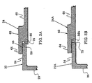
- the dimension differential between the lid dimension 70 and the aperture dimension 72 is selected to cause the lid periphery 58 to then abut the aperture periphery 56 and create mutually-induced radial stresses in the lid 24 and the housing 22. These stresses wedge the aperture periphery 56 into the groove 66 as shown in FIG. 3A.
- the dimension differential is selected to be sufficient to elastically buckle the lid 24 into its final configuration 24F of FIG. 2 and thereby cause the lid periphery 58 to exert a buckling stress against the aperture periphery 56.
Landscapes
- Engineering & Computer Science (AREA)
- Manufacturing & Machinery (AREA)
- Control Of Motors That Do Not Use Commutators (AREA)
- Pressure Welding/Diffusion-Bonding (AREA)
- Non-Reversible Transmitting Devices (AREA)
Claims (9)
- Structure passive pour hyperfréquences (100 ; 102 ; 104 ; 20 ; 90 ; 96), comprenant :caractérisée parun bâti (22),une ouverture (28) formée par ledit bâti (22), ladite ouverture (28) ayant une périphérie d'ouverture (56) et dimensionnée pour avoir une dimension d'ouverture (72) sur toute l'ouverture (28) etun capot (24) ayant une périphérie de capot (58) et dimensionné pour avoir une dimension de capot (70) sur tout ledit capot (24), ladite dimension de capot (70) dépassant ladite dimension d'ouverture (72) dans une configuration initiale (24I) avant installation par une différentielle dimensionnelle d'une grandeur prédéterminée,
dans une configuration finale (24F) après son installation dans ledit bâti, ledit capot (24) étant positionné sur toute ladite ouverture (28) avec ladite périphérie de capot (58) à l'intérieur de ladite périphérie d'ouverture (56) butant contre ladite périphérie d'ouverture (56), créant par ce moyen des contraintes radiales mutuellement induites dans ledit capot (24) et ledit bâti (22) à cause de ladite grandeur de ladite différentielle de dimension. - Structure selon la revendication 1, caractérisée par le fait d'être un boítier d'hyperfréquence (100 ; 102 ; 104) pour enfermer et blinder des composants électroniques (92 ; 94 ; 86).
- Structure selon la revendication 1, caractérisée par le fait d'être un filtre d'hyperfréquence (20 ; 90 ; 96).
- Filtre selon la revendication 3, caractérisé par un tronçon de filtre (32) s'étendant de l'un desdits bâtis (22) et desdits capots (24) et orienté vers l'autre desdits bâtis (22) et desdits capots (24) ;
et les premier et second ports d'accès (34, 36) qui communiquent par le biais d'au moins l'un desdits bâtis (22) et desdits capots (24). - Structure selon l'une quelconque des revendications 1 à 4, caractérisée en ce que la grandeur de ladite différentielle de dimension est telle que ledit capot (24) est voilé de manière élastique, ledit capot (24) exerçant ainsi une tension de voilement contre ladite périphérie d'ouverture (56).
- Structure selon l'une quelconque des revendications 1 à 5, caractérisée par une rainure (66) formée par l'une desdites périphéries d'ouverture (56) et desdites périphéries de capot (58) et dans laquelle l'autre desdites périphéries d'ouverture (56) et desdites périphéries de capot (58) est bloquée dans ladite rainure (66) par lesdites contraintes mutuellement induites.
- Structure selon l'une quelconque des revendications 1 à 5, caractérisée par un bord biseauté (79) formé par l'une desdites périphéries d'ouverture (56) et desdites périphéries de capot (58) et dans laquelle l'autre desdites périphéries d'ouverture (56) et desdites périphéries de capot (58) bute contre ledit bord biseauté (79) et un rebord (64) formé par l'une desdites périphéries d'ouverture (56) et desdites périphéries de capot (58) et dans laquelle ledit rebord (64) s'étend sur l'autre desdites périphéries d'ouverture (56) et desdites périphéries de capot (58) pour augmenter le maintien dudit capot (24) dans ladite ouverture (28).
- Procédé pour réunir des éléments (22, 24) dans des structures passives pour hyperfréquences (20 ; 90 ; 96 ; 100 ; 102 ; 104) pour réduire l'intermodulation passive, comprenant les étapes qui consistent à :caractérisée parproposer une ouverture (28) dans un premier élément (22), dans lequel ladite ouverture (28) a une périphérie d'ouverture (56) et une dimension d'ouverture (72) sur toute ladite ouverture (28),proposer un second élément (24) dans lequel ledit second élément (24) a une périphérie de second élément (58) et une dimension de second élément (70) sur tout ledit second élément (24),ladite dimension de second élément (70) dépassant ladite dimension d'ouverture (72) dans une configuration initiale (24I) avant installation par une différentielle de dimension ayant une grandeur prédéterminée,
le fait pour lesdits premier et second éléments (22, 24) d'avoir une différentielle de température qui est suffisante pour permettre audit second élément (24) d'être positionné sur toute ladite ouverture (28) avec ladite périphérie de second élément (58) à l'intérieur de ladite périphérie d'ouverture (56),
le fait de supprimer ladite différentielle de température, proposant par ce moyen une configuration finale d'installation, dans laquelle ledit capot (24) est positionné sur toute ladite ouverture (28) avec ladite périphérie de capot (58) à l'intérieur de ladite périphérie d'ouverture (56) butant contre ladite périphérie d'ouverture (56) et
le fait de sélectionner ladite différentielle de dimension pour être suffisante pour créer des contraintes mutuellement induites dans lesdits premier et second éléments (22, 24) à cause de ladite grandeur de ladite différentielle dimensionnelle, lorsque ladite étape de suppression de différentielle de température est achevée,
qui réduisent l'intermodulation passive. - Procédé selon la revendication 8, caractérisé par l'étape qui consiste à sélectionner ladite différentielle de dimension pour être suffisante pour voiler de manière élastique ledit second élément (24), lorsque ladite étape de suppression est achevée, et pour faire en sorte par ce moyen que ladite périphérie de second élément (58) exerce une tension de voilement contre ladite périphérie d'ouverture (56).
Applications Claiming Priority (2)
| Application Number | Priority Date | Filing Date | Title |
|---|---|---|---|
| US08/699,748 US5834993A (en) | 1996-08-20 | 1996-08-20 | Passive microwave structure and methods having reduced passive intermodulation |
| US699748 | 1996-08-20 |
Publications (3)
| Publication Number | Publication Date |
|---|---|
| EP0825665A2 EP0825665A2 (fr) | 1998-02-25 |
| EP0825665A3 EP0825665A3 (fr) | 1999-05-19 |
| EP0825665B1 true EP0825665B1 (fr) | 2003-04-02 |
Family
ID=24810732
Family Applications (1)
| Application Number | Title | Priority Date | Filing Date |
|---|---|---|---|
| EP97111889A Expired - Lifetime EP0825665B1 (fr) | 1996-08-20 | 1997-07-12 | Structures pour hyperfréquences passives et méthodes à intermodulation passive réduite |
Country Status (4)
| Country | Link |
|---|---|
| US (2) | US5834993A (fr) |
| EP (1) | EP0825665B1 (fr) |
| CA (1) | CA2210113C (fr) |
| DE (1) | DE69720350T2 (fr) |
Families Citing this family (5)
| Publication number | Priority date | Publication date | Assignee | Title |
|---|---|---|---|---|
| US5834993A (en) * | 1996-08-20 | 1998-11-10 | Hughes Electronics Corporation | Passive microwave structure and methods having reduced passive intermodulation |
| FI115333B (fi) | 1999-12-01 | 2005-04-15 | Remec Oy | Resonaattorirakenteen sisäjohtimen kiinnitysjärjestely ja menetelmä resonaattorirakenteen sisäjohtimen kiinnittämiseen |
| USD452774S1 (en) | 2000-06-21 | 2002-01-08 | Hyung Tae Kim | Strap connection device for bags |
| USD459079S1 (en) | 2000-07-01 | 2002-06-25 | Hyung Tae Kim | Strap catch device for bags |
| US20030052749A1 (en) * | 2001-09-04 | 2003-03-20 | In Kui Cho | Resonator, method for manufacturing filter by using resonator and filter manufactured by the same method |
Family Cites Families (25)
| Publication number | Priority date | Publication date | Assignee | Title |
|---|---|---|---|---|
| CA518595A (fr) * | 1955-11-15 | Star Watch Case Company | Methode de montage de verre dans biseaux de montre | |
| US1981334A (en) * | 1930-07-17 | 1934-11-20 | Colt S Mfg Co | Article of manufacture |
| US3371413A (en) * | 1966-10-26 | 1968-03-05 | Amphenol Corp | Hermetically sealed connector |
| DE1949924B2 (de) * | 1969-10-03 | 1970-08-20 | Schenck Gmbh Carl | Elektromechanische Kraftmessdose |
| US3714606A (en) * | 1971-07-12 | 1973-01-30 | Motorola Inc | Temperature compensated tuner and oscillator |
| US3928167A (en) * | 1971-12-23 | 1975-12-23 | Rhone Progil | Improvements in methods of producing electrolytic anode assemblies |
| US4001928A (en) * | 1973-01-04 | 1977-01-11 | Raychem Corporation | Method for plugging an aperture with a heat recoverable plug |
| US4126758A (en) * | 1973-12-03 | 1978-11-21 | Raychem Corporation | Method for sealing integrated circuit components with heat recoverable cap and resulting package |
| US4015319A (en) * | 1975-03-20 | 1977-04-05 | Bindicator Company | Method for manufacturing an ultrasonic transducer |
| US4879799A (en) * | 1976-10-29 | 1989-11-14 | Raychem Corporation | Heat-recoverable article |
| US4104556A (en) * | 1976-11-15 | 1978-08-01 | Gte Laboratories Incorporated | High energy radio frequency pulse generators |
| US4074407A (en) * | 1977-03-17 | 1978-02-21 | Roll-Rite Corporation | Method for making a hollow-bodied caster wheel |
| CH623711B (de) * | 1978-12-15 | Bbc Brown Boveri & Cie | Uhr. | |
| DE2936781A1 (de) * | 1979-09-12 | 1981-04-02 | Varta Batterie Ag, 3000 Hannover | Galvanisches element |
| US4628283A (en) * | 1983-11-07 | 1986-12-09 | The Narda Microwave Corporation | Hermetically sealed oscillator with dielectric resonator tuned through dielectric window by adjusting screw |
| US4648124A (en) * | 1985-04-04 | 1987-03-03 | The United States Of America As Represented By The Secretary Of The Air Force | Apparatus for locating passive intermodulation interference sources |
| CH667832A5 (de) * | 1985-04-10 | 1988-11-15 | Metoxit Ag | Verfahren zum kraftschluessigen verbinden eines zylindrrischen keramikteils mit einem aus eisenwerksstoff besstehenden flansch. |
| DE3542176A1 (de) * | 1985-11-29 | 1987-06-04 | Vaw Ver Aluminium Werke Ag | Fluessigkeitsbehaelter aus einer aluminium-gusslegierung |
| JPS63289306A (ja) * | 1987-05-22 | 1988-11-25 | 日本特殊陶業株式会社 | 摺動部品の製造法 |
| US4907330A (en) * | 1987-06-04 | 1990-03-13 | Ngk Spark Plug Co., Ltd. | Sintered body assembly formed from a plurality of independent compacts and method of producing same |
| JPH0271595A (ja) * | 1988-09-06 | 1990-03-12 | Maspro Denkoh Corp | シールドケース |
| DE4032803A1 (de) * | 1990-10-16 | 1992-04-30 | D O R N E Y Technologie Gmbh | Formteil aus einem metallischen und einem keramischen koerper |
| US5456779A (en) * | 1994-06-27 | 1995-10-10 | Lockheed Missiles & Space Company, Inc. | Method of attaching antenna mesh |
| US5834993A (en) * | 1996-08-20 | 1998-11-10 | Hughes Electronics Corporation | Passive microwave structure and methods having reduced passive intermodulation |
| US5818314A (en) * | 1997-05-12 | 1998-10-06 | Hughes Electronics Corporation | Tunable electromagnetic wave resonant filter |
-
1996
- 1996-08-20 US US08/699,748 patent/US5834993A/en not_active Expired - Fee Related
-
1997
- 1997-07-09 CA CA002210113A patent/CA2210113C/fr not_active Expired - Lifetime
- 1997-07-12 DE DE69720350T patent/DE69720350T2/de not_active Expired - Lifetime
- 1997-07-12 EP EP97111889A patent/EP0825665B1/fr not_active Expired - Lifetime
-
1998
- 1998-04-09 US US09/057,945 patent/US6044538A/en not_active Expired - Lifetime
Also Published As
| Publication number | Publication date |
|---|---|
| CA2210113A1 (fr) | 1998-02-20 |
| US5834993A (en) | 1998-11-10 |
| CA2210113C (fr) | 2002-01-01 |
| DE69720350D1 (de) | 2003-05-08 |
| EP0825665A3 (fr) | 1999-05-19 |
| DE69720350T2 (de) | 2004-02-12 |
| EP0825665A2 (fr) | 1998-02-25 |
| US6044538A (en) | 2000-04-04 |
Similar Documents
| Publication | Publication Date | Title |
|---|---|---|
| JP6526345B1 (ja) | Pim測定のためのフィルタ構造 | |
| US6803835B2 (en) | Integrated filter balun | |
| US5066933A (en) | Band-pass filter | |
| EP0736923B1 (fr) | Technique de compensation de dispersion et dispositif pour les filtres hyperfréquences | |
| EP0131633A1 (fr) | Convertisseur de frequence | |
| US8005451B2 (en) | Filter circuit and radio communication apparatus | |
| US6044538A (en) | Passive microwave structures and methods having reduced passive intermodulation | |
| US4331943A (en) | Acoustic wave devices having transverse mode distortions eliminated structurally | |
| US5274340A (en) | Microwave multistage amplifier | |
| EP0190902B1 (fr) | Circuit mélangeur | |
| JP3112825B2 (ja) | マイクロ波装置 | |
| JPH09205302A (ja) | 誘電体フィルタ | |
| JP2000091806A (ja) | バンドエリミネーションフィルタ | |
| Menargues et al. | High-power tests in Additive Manufacturing Ka-band feeds and feed components | |
| Subramanyam et al. | High power combline filter for deep space applications | |
| US11749873B2 (en) | High-frequency module | |
| Lui et al. | Measurement of intermodulation products generated by structural components | |
| KR101134832B1 (ko) | 프론트앤드모듈의 공진기 | |
| US5093629A (en) | Amplifier circuit having second order signal cancellation | |
| EP0491505B1 (fr) | Combinateur intégré à guides d'ondes | |
| US12512572B2 (en) | Filters including dual cross-couplings and related combiners | |
| JPS62291201A (ja) | マイクロ波集積回路 | |
| US20030038687A1 (en) | Power limiting apparatus | |
| JPH1098311A (ja) | マイクロ波装置 | |
| CN115955256A (zh) | 一种面向航天应用的s频段测控收发隔离系统 |
Legal Events
| Date | Code | Title | Description |
|---|---|---|---|
| PUAI | Public reference made under article 153(3) epc to a published international application that has entered the european phase |
Free format text: ORIGINAL CODE: 0009012 |
|
| AK | Designated contracting states |
Kind code of ref document: A2 Designated state(s): DE FR GB |
|
| RAP1 | Party data changed (applicant data changed or rights of an application transferred) |
Owner name: HUGHES ELECTRONICS CORPORATION |
|
| PUAL | Search report despatched |
Free format text: ORIGINAL CODE: 0009013 |
|
| AK | Designated contracting states |
Kind code of ref document: A3 Designated state(s): AT BE CH DE DK ES FI FR GB GR IE IT LI LU MC NL PT SE |
|
| 17P | Request for examination filed |
Effective date: 19991021 |
|
| AKX | Designation fees paid |
Free format text: DE FR GB |
|
| 17Q | First examination report despatched |
Effective date: 20011218 |
|
| GRAH | Despatch of communication of intention to grant a patent |
Free format text: ORIGINAL CODE: EPIDOS IGRA |
|
| GRAH | Despatch of communication of intention to grant a patent |
Free format text: ORIGINAL CODE: EPIDOS IGRA |
|
| GRAA | (expected) grant |
Free format text: ORIGINAL CODE: 0009210 |
|
| AK | Designated contracting states |
Designated state(s): DE FR GB |
|
| REG | Reference to a national code |
Ref country code: GB Ref legal event code: FG4D |
|
| REF | Corresponds to: |
Ref document number: 69720350 Country of ref document: DE Date of ref document: 20030508 Kind code of ref document: P |
|
| ET | Fr: translation filed | ||
| PLBE | No opposition filed within time limit |
Free format text: ORIGINAL CODE: 0009261 |
|
| STAA | Information on the status of an ep patent application or granted ep patent |
Free format text: STATUS: NO OPPOSITION FILED WITHIN TIME LIMIT |
|
| 26N | No opposition filed |
Effective date: 20040105 |
|
| REG | Reference to a national code |
Ref country code: FR Ref legal event code: PLFP Year of fee payment: 20 |
|
| PGFP | Annual fee paid to national office [announced via postgrant information from national office to epo] |
Ref country code: DE Payment date: 20160726 Year of fee payment: 20 Ref country code: GB Payment date: 20160727 Year of fee payment: 20 |
|
| PGFP | Annual fee paid to national office [announced via postgrant information from national office to epo] |
Ref country code: FR Payment date: 20160726 Year of fee payment: 20 |
|
| REG | Reference to a national code |
Ref country code: DE Ref legal event code: R071 Ref document number: 69720350 Country of ref document: DE |
|
| REG | Reference to a national code |
Ref country code: GB Ref legal event code: PE20 Expiry date: 20170711 |
|
| PG25 | Lapsed in a contracting state [announced via postgrant information from national office to epo] |
Ref country code: GB Free format text: LAPSE BECAUSE OF EXPIRATION OF PROTECTION Effective date: 20170711 |