EP0825725A1 - Codage par sous-bandes avec allocation de bits adaptative - Google Patents
Codage par sous-bandes avec allocation de bits adaptative Download PDFInfo
- Publication number
- EP0825725A1 EP0825725A1 EP97114387A EP97114387A EP0825725A1 EP 0825725 A1 EP0825725 A1 EP 0825725A1 EP 97114387 A EP97114387 A EP 97114387A EP 97114387 A EP97114387 A EP 97114387A EP 0825725 A1 EP0825725 A1 EP 0825725A1
- Authority
- EP
- European Patent Office
- Prior art keywords
- frequency
- time
- dimensional
- bit
- block
- Prior art date
- Legal status (The legal status is an assumption and is not a legal conclusion. Google has not performed a legal analysis and makes no representation as to the accuracy of the status listed.)
- Ceased
Links
Images



Classifications
-
- E—FIXED CONSTRUCTIONS
- E05—LOCKS; KEYS; WINDOW OR DOOR FITTINGS; SAFES
- E05B—LOCKS; ACCESSORIES THEREFOR; HANDCUFFS
- E05B15/00—Other details of locks; Parts for engagement by bolts of fastening devices
- E05B15/10—Bolts of locks or night latches
-
- H—ELECTRICITY
- H04—ELECTRIC COMMUNICATION TECHNIQUE
- H04B—TRANSMISSION
- H04B1/00—Details of transmission systems, not covered by a single one of groups H04B3/00 - H04B13/00; Details of transmission systems not characterised by the medium used for transmission
- H04B1/66—Details of transmission systems, not covered by a single one of groups H04B3/00 - H04B13/00; Details of transmission systems not characterised by the medium used for transmission for reducing bandwidth of signals; for improving efficiency of transmission
- H04B1/667—Details of transmission systems, not covered by a single one of groups H04B3/00 - H04B13/00; Details of transmission systems not characterised by the medium used for transmission for reducing bandwidth of signals; for improving efficiency of transmission using a division in frequency subbands
-
- G—PHYSICS
- G06—COMPUTING OR CALCULATING; COUNTING
- G06T—IMAGE DATA PROCESSING OR GENERATION, IN GENERAL
- G06T9/00—Image coding
- G06T9/007—Transform coding, e.g. discrete cosine transform
-
- E—FIXED CONSTRUCTIONS
- E05—LOCKS; KEYS; WINDOW OR DOOR FITTINGS; SAFES
- E05B—LOCKS; ACCESSORIES THEREFOR; HANDCUFFS
- E05B65/00—Locks or fastenings for special use
- E05B65/0025—Locks or fastenings for special use for glass wings
Definitions
- the present invention relates to a digital signal processing method, a digital signal processing apparatus, a digital signal recording method, a digital signal recording apparatus, a recording medium, a digital signal transmission method and a digital signal transmission apparatus.
- a conventional method is a transform coding method making up one of the blocking frequency subband coding methods in which an audio signal on a time domain is blocked per unit time, and the signal on a time axis for each block is orthogonal-transformed into a signal on a frequency base thereby to divide the same into a plurality of frequency bands and to encode the same for each frequency band.
- Another conventional method is a subband coding (SBC: Subband Coding) making up one of the nonblocking frequency subband coding methods in which an audio signal in a time domain is not blocked per unit time but coded by being split into a plurality of frequency bands.
- SBC Subband Coding
- a high efficiency coding method is also available which is a combination of the above-mentioned subband coding method and the transform coding method.
- the signal for each band is orthogonally transformed into a frequency-domain signal by the above-mentioned transform coding method, and the signal is coded for each band thus orthogonally transformed.
- the subband filter used for the subband coding method includes a quadrature mirror filter (QMF: Quadrature Mirror Filter) or the like, for example, which is described in 1976 R. E. Crochiere "Digital Coding of Speech in Subbands" Bell Syst. Tech. J. Vol.55, No.8, 1976. Also, ICASSP 83, BOSTON Polyphase Quadrature Filters-A new subband coding technique, Joseph H. Rothweiler, describes an equal bandwidth filter splitting method and an apparatus using such a filter as a polyphase quadrature filter (PQF: Polyphase Quadrature Filter).
- QMF Quadrature Mirror Filter
- One of the above-mentioned orthogonal transform methods is such that, for example, an input audio signal is blocked in a predetermined unit time and transformed for each block from time axis to frequency axis by the fast Fourier transform, the discrete cosine transform (DCT) or the modified DCT transform (MDCT) or the like.
- DCT discrete cosine transform
- MDCT modified DCT transform
- a band splitting is available in which the human acoustic characteristics are taken into consideration as a frequency splitting width in quantizing each frequency component split into frequency subbands.
- the audio signal is sometimes split into a plurality of bands (say, 25 bands) by a band splitting method generally called a critical band where the high-frequency bandwidth is widened.
- a predetermined bit allocation is performed for each band, or an adaptive bit allocation is performed for each band for coding.
- the MDCT coefficient data obtained by the above-mentioned MDCT process is coded by the above-mentioned bit allocation, for example, the MDCT coefficient data obtained by the MDCT process for each block is coded by the adaptively distributed number of bits.
- Block floating Block Floating: block floating
- normalization and quantization are carried out corresponding to the maximum absolute value of the MDCT coefficient for each band. As a result, a more efficient coding is accomplished.
- the bit allocation amount for each band to be quantized is converted into an integer or the like when calculating it. Therefore, the total number of the bits assigned to all the bands generally fails to coincide with the bit rate specified in the coding format.
- a bit adjustment operation is thus required for attaining coincidence.
- a method conceivable for this bit adjusting operation consists in the simple arrangement in the order of priority depending on the frequency. In such a case, however, the input signal is not depended on at all and therefore adaptive adjusting operation is impossible. In the case where the bit adjustment strictly depending on the input is to be carried out, however, it is necessary to take into consideration the quantization error for all the signal components and the masking effect again or the like. Thus, the adjusting operation becomes very large in scale.
- the present invention has been developed in view of this actual situation, and is intended to propose a digital signal processing method, a digital signal processing apparatus, a digital signal recording method, a digital signal recording apparatus, a recording medium, a digital signal transmission method or a digital signal transmission apparatus, in which an input digital signal is split into a plurality of frequency band components thereby to obtain signal components in a plurality of time-frequency two-dimensional blocks, data are normalized based on the signal components in the two-dimensional block for each of the time-frequency two-dimensional blocks thereby to obtain normalized data, a quantization coefficient representing the feature of the signal components in the two-dimensional block for each of the time-frequency two-dimensional blocks is obtained, a bit allocation amount is determined based on the quantization coefficient thus determined, the signal components in each of the time-frequency two-dimensional blocks are quantized by the bit allocation amount and the normalized data thereby to compress information, while at the same time producing a information compression parameter for each of the time-frequency two-dimensional blocks, whereby the adjusting operation dependent on the input digital signal
- the present invention provides a digital signal processing method, in which an input digital signal is split into a plurality of frequency band components thereby to obtain signal components in a plurality of time-frequency two-dimensional blocks, data in each of the time-frequency two-dimensional blocks are normalized based on the signal components in the two-dimensional block thereby to obtain a normalized data, a quantization coefficient representing the feature of the signal components in the two-dimensional block for each of the time-frequency two-dimensional blocks is obtained, a bit allocation amount is determined based on the quantization coefficient, and the signal components in the block for each of the time-frequency two-dimensional blocks are quantized according to the normalized data and the bit allocation amount thereby to compress information, while at the same time obtaining an information compression parameter for each of the time-frequency two-dimensional blocks.
- the maximum quantization error that may occur in each of the time-frequency two-dimensional blocks is calculated based on the maximum signal component in the two-dimensional block or the normalized data and the assigned bit amount provisionally calculated, and this maximum quantization error is regarded as the degree of bit requirement for each two-dimensional block, so that the bits are adjusted based on the degree of bit requirement.
- the adjusting operation is performed in dependence on the input digital signal, so that an efficient coding is realized with a proper amount of processing as an adjusting operation thereby to improve the static characteristics and the signal quality.
- an input digital signal such as an audio PCM signal or the like is coded at a high efficiency using the techniques of subband coding (SBC), adaptive transform coding (ATC) and adaptive bit assignment.
- SBC subband coding
- ATC adaptive transform coding
- a specific high efficiency encoder shown in FIG. 1 divides an input digital signal into a plurality of frequency bands, and orthogonally transforms the same it for each frequency band, Then, the spectral data on a frequency axis thus obtained is adaptively coded by bit assignment for each of what is called the critical bands taking the human acoustic characteristics into account in low-frequency range, and for each band subdivided from the critical bandwidth taking the block floating efficiency into consideration in middle frequency range. Normally, this block constitutes the one for generating quantization noises. Further, in the embodiment of the present invention, the block size (block length) is adaptively changed in accordance with the input signal before the orthogonal transform.
- an audio signal in the frequency band of 0 to 22 kHz is sampled with the sampling frequency of 44.1 kHz, after which the input audio PCM signal obtained by PCM coding is supplied to an input terminal 100.
- This input audio PCM signal is split into the band of 0 to 11 kHz and the band of 11 kHz to 22 kHz by a band splitting filter 101 including what is called a QMF (quadrature mirror filter) filter or the like.
- the signal in the band of 0 to 11 kHz is split into the band of 0 to 5.5 kHz and the band of 5.5 kHz to 11 kHz by a band splitting filter 102 including a QMF filter or the like in similar fashion.
- the above-mentioned signal in the band of 11 kHz to 22 kHz from the band splitting filter 101 is applied to a MDCT (modified discrete cosine transform) circuit (modified discrete cosine transform means) (orthogonal transform means) 103 constituting an example of an orthogonal transform circuit for the MDCT processing.
- the signal in the band of 5.5 kHz to 11 kHz from the band splitting filter 102 is supplied to a MDCT circuit (modified discrete cosine transform means) (orthogonal transform means) 104 for the MDCT processing.
- the signal in the band of 0 to 5.5 kHz from the band splitting filter 102 is supplied to a MDCT circuit (modified discrete cosine transform means) (orthogonal transform means) 105 for the MDCT processing.
- the MDCT circuits 103, 104, 105 each perform the MDCT processing based on the block size (information compression parameter, namely length of the processing block) determined by block determining circuits 109, 110, 111, respectively, prepared for the respective bands.
- a means for splitting an input digital signal into a plurality of frequency bands is a QMF filter, for example, which is described in 1976 R.E. Crochiere Digital Coding of Speech in Subbands Bell Syst. Tech. J. Vol.55, No.8, 1976.
- ICASSP 83 Boston Polyphase Quadrature Filters-A New Subband Coding Technique Joseph H. Rothweiler, describes a method of splitting a signal with an equal bandwidth by a filter or the like.
- the orthogonal transform described above includes the one, for example, in which an input audio signal is blocked in a predetermined unit time thereby to transform the time axis transformed into a frequency axis by the fast Fourier transform (FFT), the discrete cosine transform (DCT), the modified DCT transform (MDCT) or the like for each block.
- FFT fast Fourier transform
- DCT discrete cosine transform
- MDCT modified DCT transform
- FIGs. 2A to 2D A specific example of the standard input digital signal for the block of each band supplied to the MDCT circuits 103, 104, 105 is shown in FIGs. 2A to 2D.
- output signals of the three filters each have a plurality of independent orthogonal transform block sizes for each band, and the time resolution thereof is adapted to be switched according to time characteristic, the frequency distribution, etc. of the signal.
- the orthogonal transform block size is increased to 11.6 mS as indicated by the long mode in FIG. 2A.
- the orthogonal transform block size is further split into two and four portions. Specifically, as shown by the short mode in FIG.
- all the block sizes are split into four, i.e. a time resolution of 2.9 mS, or as shown in a middle mode A of FIG. 2C or a middle mode B of FIG. 2D, a portion of the block sizes is split into two, i.e., 5.8 mS, and other portions into four, i.e. into a time resolution of 2.9 mS, thereby adapting to the actual complicated input digital signal.
- the orthogonal transform block sizes can be apparently more effective by a more complicated splitting, as far as the scale of the processing unit permits.
- This orthogonal transform block size is determined by the orthogonal transform block size determining circuits ( orthogonal transform block size determining means) 109, 110, 111 shown in FIG. 1.
- the results of the determination are supplied to the respective MDCT circuits 103, 104, 105 and to a bit assignment calculation circuit 118, while at the same time being output from output terminals 113, 115, 117 as block size information (information on the length of the processing block, namely information compression parameter) for each block.
- the spectral data on the frequency axis obtained by the MDCT processings in the MDCT circuits 103, 104, 105 or the MDCT coefficient data, which are the signal components in the time-frequency two-dimensional blocks, are gathered for each of what is called the critical bands (Critical Bands) in a low frequency range, while in a high-frequency range, on the other hand, taking the effectiveness of the block floating, the critical bandwidth is subdivided and applied to adaptive bit assignment coding circuits 106, 107, 108 and the bit assignment calculation circuit 118.
- the critical bands Critical Bands
- This critical band is a frequency range split taking the human acoustic characteristics into consideration, and constitutes a band having a noise generated by masking a given pure sound by a narrow-band noise having the same intensity in the neighborhood of the frequency of the pure sound.
- This critical band is wider in bandwidth the higher in frequency. All the frequency bands of 0 to 22 kHz described above, for example, are split into 25 critical bands.
- the bit assignment calculation circuit 118 calculates the energy or a peak value for each split band and the masking amount for each split band in consideration of the critical band and the block floating taking into consideration what is called the masking effect based on the block size information, the spectral data and the MDCT coefficient data described above. On the basis of the calculation result, the number of assigned bits for each band is determined and supplied to each of the adaptive bit assignment coding circuits 106, 107, 108.
- These adaptive bit assignment coding circuits 106, 107, 108 normalize and quantize the respective spectral data or the MDCT coefficient data in accordance with the number of bits thus assigned to each split band taking into consideration the above-mentioned block size information (information compression parameter, namely the length of the processing block), the critical band and the block floating.
- the data coded in this way are derived through output terminals 112, 114, 116 in FIG. 1.
- each split band taking into consideration the above-mentioned critical band and the block floating providing a unit for bit assignment is hereinafter called a unit block.
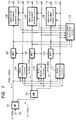
- FIG. 3 is a block circuit diagram showing a general configuration of a specific example of the bit assignment calculation circuit 118 in FIG. 1.
- an input terminal 301 is supplied with the spectral data on the frequency axis or the MDCT coefficients from the MDCT circuits 103, 104, 105 in FIG. 1 and the block size informations from the block determining circuits 109, 110, 111 in FIG. 1.
- the process is performed using the constants, the weighting functions, etc. adaptive to the block size information.
- the spectral data on the frequency axis or the MDCT coefficient data input from the input terminal 301 is supplied to a bandwise energy calculation means for each band 302, so that the energy at every unit block is determined by calculating the total sum of the amplitude values in the unit blocks, for example, or the like. Instead of the energy for each band, the peak amplitude value, the average amplitude value, etc. may be used.
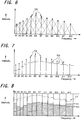
- a spectrum SB of the total sum of each band is shown in FIG. 6, as an example.
- FIG. 6 shows the case, for simplifying the illustration, the case in which the block is split into 12 unit blocks (B1 to B12).
- the broken lines in FIG. 6 indicate the effect that the spectrum SB of the total sum of each band has an effect on the other portions and corresponds to the weighting of the convolution.
- the energy calculation circuit 302 determines a scale factor (normalized data) value providing the normalized data indicating the state of the block floating of the unit block.
- a scale factor value providing the normalized data indicating the state of the block floating of the unit block.
- the scale factor value can be numbered using several bits corresponding to the actual value and the number is stored by a ROM or the like (not shown).
- the scale factor value determined by the above-mentioned method for a certain unit block is the number attached using the above-mentioned bits corresponding to the determined value as subsidiary information indicating the scale factor of the unit block.
- the convolution filter circuit 303 includes, for example, a plurality of delay elements for sequentially delaying the input data, a plurality of multipliers for multiplying filter coefficients (weighting functions) with the outputs of the delay elements, and a total sum adder for taking the total sum of the outputs of the respective multipliers.
- This convolution process can produce the total sum of the portions indicated by the broken lines in FIG. 6.
- the output of the above-mentioned convolution filter circuit 303 is supplied to a subtractor 304.
- This subtractor 304 is for determining a level ⁇ corresponding to a tolerable noise level described layer in a convoluted region.
- the level ⁇ corresponding to the tolerable noise level is such that a tolerable noise level is attained for each critical band by an inverted convolution process as described later.
- the above-mentioned subtractor 304 is supplied with a tolerable function, which is a function representing the masking level for determining the level ⁇ .
- the level ⁇ is controlled by increasing and decreasing the tolerable function.
- the tolerable function is supplied from a (n-ai) function generating circuit 305 as described below.
- n and a are constants where a > 0, and S is the intensity of a convoluted bark spectrum (Bark Spectrum) (a unit of the critical band representing one spectrum for each critical band).
- the above-mentioned level ⁇ is determined, which the resulting data is supplied to a divider 306.
- the divider 306 is for performing an inverted convolution of the level ⁇ in the convoluted region as described above. By performing this inverted convolution, therefore, a masking spectrum can be obtained from the above-mentioned level ⁇ . In other words, this masking spectrum provides a tolerable noise spectrum.
- the above-mentioned inverted convolution process which requires a complicated calculation, can be performed using the simplified divider 306 according to this embodiment.
- the above-mentioned masking spectrum is supplied to a subtractor 308 through a synthesis circuit 307.
- the subtraction circuit 308 is supplied with the output from the energy detection circuit 302 for each band described above, i.e., the spectrum SB described above, through a delay circuit 309. Consequently, the subtraction circuit 308 performs the subtraction between the above-mentioned masking spectrum and the spectrum SB, thereby masking the portion of the above-mentioned spectrum SB equal to or lower in level than that of a particular masking spectrum MS,as shown in FIG. 7.
- a minimum audible curve RC representing the human acoustic characteristic as shown in FIG. 8 supplied from a minimum audible curve generating circuit 312 is synthesized with the above-mentioned masking spectrum MS. If the absolute noise level of a noise is equal to or lower than the minimum audible curve, the noise is not audible. This minimum audible curve, if coded the same way, becomes different by the difference in the reproduction volume, for example, at the time of playback. In an actual digital system, however, music applied to the 16-bit dynamic range, for example, is not substantially different.
- the quantization noise in the audible frequency range of about 4 kHz easiest to hear is not audible, for example, it is considered that the quantization noise below the level of this minimum audible curve cannot be heard in the other frequency ranges.
- the system is used in such a manner that the noise is not heard in the neighborhood of 4 kHz in the word length of the system, for example.
- the resulting tolerable noise level can be defined up to the hatched portion in FIG. 8.
- the 4 kHz level of the above-mentioned minimum audible curve is set to the lowest level equivalent to 20 bits, for example.
- FIG. 8 shows a signal spectrum SS at the same time.
- a tolerable noise correcting circuit 310 corrects the tolerable noise level of the output from the above-mentioned subtractor 308 based on the information of an equal loudness-level curve, for example.
- the equal loudness-level curve is defined as a characteristic curve for the human acoustic characteristic formed by connecting the sound levels of the frequencies audible with the same loudness as the pure sound of 1 kHz, for example, and is also called the loudness equal sensitivity curve. Also, this equal loudness-level curve is plotted substantially in the same curve as the minimum audible curve RC shown in FIG. 8.
- the tolerable noise correcting circuit 310 provisionally calculates the assigned bits for each unit block based on various parameters including the masking, the acoustic characteristics and so on described above.
- the tolerable noise correcting circuit 310 performs the correcting operation for attaining the coincidence.
- This correction method can be implemented in such a manner as to maintain the relative relations of the assigned bits calculated for each unit block, so that in the case where the total number of the assigned bits calculated as above is smaller than the number of usable bits, for example, the number of all the assigned bits is uniformly increased as shown in FIG. 9. In the case where the total number of assigned bits calculated as above is greater than the number of usable bits, on the other hand, the number of all the assigned bits is uniformly decreased as shown in FIG. 10.
- the tolerable noise correcting circuit 310 produces the assigned bits for each unit block after this correcting operation is carried out.
- This correcting operation though performed using the tolerable noise correcting circuit 310 in the foregoing description, can alternatively be performed in the stage preceding to the above-mentioned tolerable noise correcting circuit 310 in the case where the fraction adjustment described later is performed in the final stage of processing after the correcting process in FIG. 3.
- the above-mentioned correcting operation can realize substantially the same total number of assigned bits as the number of usable bits. Since the bit assignment value of each unit block determined by the preceding series of process is calculated as a real number, however, conversion into an integer by disregarding or the like is sometimes required in actual practices. Also, the unit blocks for which more than the maximum number of assigned bits permitted by the coding format is calculated or the unit blocks calculated as a negative value by the above-mentioned correcting operation require conversion into an integer as a bit assignment value in the range allowable by the coding format. Generally, this operation of converting into an integer causes the excess or shortage of bits as the total number of reassigned bits fails to coincide with the number of usable bits determined by the bit rate.
- a fraction adjusting circuit 313 in FIG. 3 calculates a maximum quantization error that may occur in each unit block from the maximum signal component in the unit block or from the bit assignment providing the word length or the normalized data constituting the scale factors for each unit block, and performs the fraction adjusting operation based on the magnitude of the maximum quantization error as the degree of bit requirement for each unit block.
- FIG. 11 shows an example showing the state of a unit block assigned with three bits.
- the ordinate represents the magnitude of the spectral data or the MDCT coefficient with the center thereof as zero, and the abscissa represents the frequency.
- eight spectral data or MDCT coefficients indicated by a, b, c, d, e, f, g and h are existent in the unit block, each having a magnitude in positive or negative direction from zero.
- the scale factor indicating the block floating state as described above is prepared in several values of positive values, out of which the minimum one assuming a value larger than the maximum absolute value of the spectral data or the MDCT coefficients, as the case may be, in the unit block is employed as a scale factor for the unit block.
- the scale factor value is selected by the spectrum a indicating the maximum absolute value. This scale factor and the size of bit assignment are used to determine the width of quantization in the unit block.
- the example shown in FIG. 11 represents the case in which three bits are assigned. Although eight values can be originally expressed by coding with three bits, the case under consideration is such that three values are taken as quantization widths equally split in positive and negative directions about zero, so that seven quantization values are taken including zero while the remaining one code that can be expressed with three bits is not used.
- the quantization value is determined from the scale factor value and the bit assigned value in the unit block, so that the spectral data or the MDCT coefficients in the unit block are quantized to the nearest quantization value.
- the black circles in FIG. 11 show the quantized values of the respective MDCT coefficients or the spectral data in the unit block. In other words, FIG. 11 shows an example of requantization (normalization followed by quantization).
- the quantization width QV for a given unit block can be determined by equation (2) below where the value of the scale factor is SF and the number of assigned bits is Nb of the same unit block.
- QV SF/ ⁇ 2 (Nb-1) -1 ⁇ , where Nb ⁇ 2
- the maximum quantization error that c occur in the unit block is QV/2, that is one half of the quantization width.
- the unit block having zero bit assignment all the spectra or the MDCT data in the unit block are quantized to zero.
- the maximum quantization error that can occur in the unit block in this case therefore, assumes the maximum absolute value of the spectra or the MDCT data in the unit block.
- the fraction adjusting circuit 313 first calculates the maximum quantization error that can occur in each of all the unit blocks using the above-mentioned method, and regards this value as the degree of bit requirement for each of the unit blocks. After that, if the total number of the assigned bits calculated is smaller than the usable number of bits and has excess bits, then the unit block having the maximum degree of bit requirement is detected and the excess bits are assigned to the same unit block. As for the unit block newly assigned with the excess bits, the degree of bit requirement is calculated anew by the above-mentioned method using the bit assignment value after the excess bit assignment.
- the fraction adjusting circuit 313 repeats a series of steps including the detection of a unit block having the maximum degree of bit requirement, assignment of excess bits and recalculation of the degree of bit requirement for the unit block as long as the assignment of excess bits is possible.
- the bit of the maximum value allowable by the coding format has already been assigned to a unit block so that the bit assignment cannot be increased for the unit block or the excess bits are not sufficient in number to increase the bit assignment to a unit block due to the number of spectra in the unit block, then such unit blocks are removed as an object of the adjusting operation.
- the adjustment of excess bits can be performed not only in the fraction adjusting circuit 313 but also in a coding correction circuit 314 as well.
- the bit shortage adjusting process is not necessarily performed in the coding correction circuit 314.
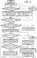
- Step ST-1 sets the block number to zero, and then the process proceeds to step ST-2 for deciding whether the bit assignment is zero or not. If the decision in step ST-2 is YES, the process proceeds to step ST-3 for setting the bit requirement degree equal to the maximum absolute value of the signal component in the block. If the decision is NO, on the other hand, the process proceeds to step ST-4 for setting the bit requirement degree equal to the maximum quantization error (QV/2). After steps ST-3 and ST-4, the process proceeds to step ST-5.
- Step ST-5 decides whether or not the number of recorded blocks is equal to the block number plus one. If the decision is NO, the process proceeds to step ST-6 for increasing the block number by one, and then the process returns to step ST-2. If the decision is YES, on the other hand, the process proceeds to step ST-7 for deciding whether or not the number of usable bits is equal to or larger than the total number of assigned bits.
- step ST-7 the process proceeds to step ST-9 for carrying out the bit shortage process (processes at step ST-9 and subsequent steps in FIG. 5). If the decision in step ST-7 is YES, on the other hand, the process proceeds to step ST-8 for setting all the blocks as adjustable blocks. After step ST-8, the process is passed to step ST-10 for deciding whether there exists an adjustable block or not. If the decision in step ST-10 is NO, the process is terminated, while if the decision is YES in step ST-10, the process proceeds to step ST-11 for detecting a block having the maximum bit requirement degree among the adjustable blocks.
- step ST-11 the process proceeds to step ST-12 for deciding whether or not the bit assignment of the detected block can be incremented by one stage. If the decision in step ST-11 is NO, the process proceeds to step ST-14 for resetting the detected block from an adjustable block to a non-adjustable block, after which the process returns to step ST-10. If the decision is YES, on the other hand, the process proceeds to step ST-13 for incrementing the bit assignment of the detected block by one stage.
- step ST-13 the process proceeds to step ST-15 for calculating the bit requirement degree (maximum quantization error QV/2) of the detected block.
- step ST-15 the process is passed to step ST-16 for calculating the total number of assigned bits, and then returns to step ST-11.
- a unit block having a minimum bit requirement degree is detected and the bits are deleted from the same unit block.
- the bit requirement degree for the unit block from which bits are deleted is recalculated by the above-mentioned method using the bit assignment value after bit deletion.
- the fraction adjusting circuit 313 repeats the series of process of detecting a unit block having a minimum bit requirement degree, deleting the bits from it and recalculating the bit requirement degree thereof until the total number of assigned bits is reduced below the number of usable bits. In the process, a unit block having a bit assignment of zero is removed as an object of adjusting operation.
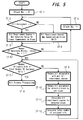
- step ST-1 sets the block number to zero
- step ST-2 for deciding whether the bit assignment is equal to zero or not. If the decision in step ST-2 is YES, the process proceeds to step ST-3 for setting the bit requirement degree equal to the maximum absolute value of the signal component in the block. In the case where the decision in step ST-2 is NO, on the other hand, the process proceeds to step ST-4 for setting the bit requirement degree equal to the maximum quantization error (QV/2). After steps ST-3 and ST-4, the process proceeds to step ST-5.
- Step ST-5 decides whether or not the number of recorded blocks is equal to the block number plus one. If the decision is NO, the process proceeds to step ST-6 for increasing the block number by one and then returns to step ST-2. When the decision in step ST-5 is YES, on the other hand, the process proceeds to step ST-7 for deciding whether or not the number of usable bits is equal to or larger than the total number of assigned bits.
- the process of steps ST-1 to ST-7 is shared by the excess bit processing shown in FIG. 4.
- step ST-7 If the decision in step ST-7 is YES, the process proceeds to step ST-8 for carrying out the excess bit process (the process in and after step ST-8 in FIG. 4). In the case where the decision in step ST-7 is NO, on the other hand, the process proceeds to step ST-9 for detecting a block having the minimum bit requirement degree among those adjustable blocks (blocks having a bit assignment of other than zero), after which the process is passed to step ST-10.
- Step ST-10 reduces the bit assignment for the detected block by one stage, and then the process proceeds to step ST-11.
- Step ST-11 calculates the bit requirement degree of the detected block, after which the process proceeds to step ST-12.
- Step ST-12 calculates the total number of assigned bits, and then the process returns to step ST-7.
- the above-mentioned fraction processing is possible also in the form not dependent on the input signal.
- the adjusting operations can be combined in such a way, therefore, that the excess bit processing is adjusted by determining the bit requirement degree as described above while performing the short bit processing by adjustment in a manner not dependent on the input signal, or in such a way that the excess bit processing is performed in dependence on the input signal while the short bit adjusting processing is performed by determining the bit requirement degree as described above.
- the output from the fraction processing circuit 313, i.e., the bit assignment value after fraction adjustment for each unit block is applied to the coding correction circuit 314.
- the coding correction circuit 314 detects a unit block having a minimum one of previously prepared scale factors, which unit block has all the spectra or the MDCT coefficients, which are the signal components in the time-frequency two-dimensional block thereof quantized to zero in spite of the assignment of two or more bits thereto. Then, the bit assignment for the unit block is reduced to zero, so that the bits that have been used for the code of spectral data or the MDCT coefficient are omitted and the bits obtained by the omission are effectively distributed.
- FIG. 12 like FIG. 11, shows the manner in which a certain unit block is requantized.
- the vertical direction represents the magnitude of the spectrum or the magnitude of the MDCT coefficient which is the signal component in a time-frequency two-dimensional block
- the horizontal direction represents the frequency.
- Eight spectra or MDCT coefficients are present in the unit block.
- the maximum absolute value of the MDCT coefficient or the spectrum in the unit block is smaller than the minimum scale factor prepared in advance, and the scale factor value for the unit block is the smallest one among those prepared in advance.
- the assigned bits are two bits which assume zero and one value each in positive and negative directions for a total of three quantized values, as shown in FIG. 12.
- the coding correction circuit 314 detects a unit block of which the coding can be corrected by the above-mentioned method using the equation of expression (3) below, and thus the bit assignment is corrected to zero thereby to produce a new usable bit.
- subsidiary information is available indicating the effectiveness of a unit block, that is, indicating whether a unit block is to be recorded or not, other than the subsidiary information indicating a substantial bit assignment for reducing the bit assignment to zero, for example. If the subsidiary information indicating the effectiveness of the unit block is used not to code the block, the scale factor representing the subsidiary information of the processing block and the bits of the subsidiary information that have been used for bit assignment can also be omitted. In such a case, too, the subsidiary information can be changed into an adaptive form by the coding correction circuit 314 shown in FIG. 3 thereby to omit the bits and produce new usable bits.
- the coding correction circuit 314 redistributes the newly-acquired usable bits in the case where the correction by the above-mentioned method is possible. In the process of redistribution, it is apparent that the adjusting operation is possible by calculating the bit requirement degree for a unit black that was carried out in the above-mentioned fraction adjusting circuit 313.
- the data thus corrected by the coding correction circuit 314 are produced as an output from a bit assignment calculation circuit 118 in FIG. 1 from an output terminal.
- the above-mentioned system shown in FIG. 3 can produce main information by the data processing the orthogonal transform output spectrum by the subsidiary information, and subsidiary information including the scale factor indicating the block floating condition and the word length indicating the length of the word. Based on these informations, the adaptive bit assignment coding circuits 106, 107, 108 in FIG. 1 actually carry out the requantization and the coding operation in a way conforming to the coding format.
- the MDCT coefficient quantized for each band i.e., the data equivalent to the output signals at the output terminals 112, 114, 116 in FIG. 1 are applied to an input terminal 1307 in FIG. 13, while the block size information that has been used, i.e., the data equivalent to the output signals of the output terminals 113, 115, 117 in FIG. 1 are applied to an input terminal 1308 in FIG. 13.
- An adaptive bit assignment decoding circuit (adaptive bit assignment decoding means) 1306 cancels the bit assignment using the adaptive bit assignment information.
- IMDCT inverted orthogonal transform
- IQMF band synthesis filter
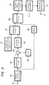
- a symbol ENC designates the encoder of FIG. 1, a symbol Tin an input terminal 100 thereof, a symbol DEC the decoder in FIG. 13, and a symbol Tout an output terminal 1300 thereof.
- the input digital signal from the input terminal Tin is supplied to and encoded in the encoder ENC.
- the output of the encoder ENC i.e., the output signals from the output terminals 112, 114, 116 and 113, 115, 117 of the encoder in FIG. 1 are supplied to a modulation means MOD thereby to multiplex and then carry out a predetermined modulation, or each output signal is modulated and then multiplexed or remodulated.
- the modulated signal from the modulation means MOD is recorded on a recording medium M by a recording means such as a magnetic head, an optical head, etc.
- the recorded signal on the recording medium M of FIG. 14 is reproduced by a reproduction means P such as a magnetic head, an optical head, etc., and the reproduced signal is demodulated by a demodulation means DEM in accordance with the modulation of the modulation means MOD.
- the demodulated output from the demodulation means DEM i.e., the signals corresponding to the outputs from the output terminals 112, 114, 116 of the encoder shown in FIG. 1 are supplied to the input terminal 1307 of the decoder shown in FIG. 13.
- the signals corresponding to the outputs from the output terminals 113, 115, 117 of the encoder shown in FIG. 1 are supplied to the input terminal 1308 of FIG. 13 to be decoded.
- An output digital signal corresponding to the input digital Signal thus is output at the output terminal Tout.
- the input digital signal from the input terminal Tin is encoded by being supplied to an encoder ENC and then encoded thereby.
- the output of the encoder ENC i.e., the output signals from the output terminals 112, 114, 116 and 113, 115, 117 of the encoder of FIG. 1 are applied to a modulation means MOD, multiplexed and then subjected to a predetermined modulation, or each output signal, after being modulated, is multiplexed or remodulated.
- the modulated signal from the modulation means MOD is supplied to a transmission means TX, and after frequency conversion, amplification and the like, a transmission signal is produced. This transmission signal is transmitted by a transmission antenna ANT-T constituting a part of the transmission means TX.
- the transmission signal from the transmission antenna ANT-T shown in FIG. 16 is received by a receiving antenna ANT-R constituting a part of a receiving means RX.
- the receiving signal is amplified and inversely frequency-converted by the receiving means RX.
- the receiving signal from the receiving means RX is demodulated by a demodulation means DEM in accordance with the modulation by the modulation means MOD.
- the demodulated output from the demodulation means DEM i.e., the signals corresponding to the outputs from the output terminals 112, 114, 116 of the encoder shown in FIG. 1 are supplied to the input terminal 1307 of the decoder shown in FIG. 13.
- the signals corresponding to the outputs from the output terminals 113, 115, 117 of the encoder shown in FIG. 1 are applied to the input terminal 1308 shown in FIG. 13 to be decoded, so that an output digital signal corresponding to the input digital signal is produced at an output terminal Tout.
- the present invention is not limited to the above-mentioned embodiments.
- the above-mentioned recording-reproduction medium is not necessarily integrated with and the signal compressor or the expander.
- the signal compressor is not necessarily integrated with the expander through the recording medium. Instead, the signal compressor can be connected with the expander by a data transfer line or the like.
- the invention is applicable not only to the audio PCM signal but also to the signal processing units such as for the digital audio signal or the digital video signal et.ct. as well.
- the recording capacity of the recording medium according to the present invention can be effectively utilized by recording the data compressed by the above-mentioned digital signal processing apparatus.
- a magnetic disk, an IC memory or a card having the IC memory built therein, a magnetic tape or other various recording media can be used in addition to the above-mentioned optical disk as a recording medium according to the present invention.
- a digital signal processing method a digital signal processing apparatus, a digital signal recording method, a digital signal recording apparatus, a recording medium, a digital signal transmission method or a digital signal transmission apparatus, wherein an input digital signal is split into a plurality of frequency band components thereby to obtain signal components in a plurality of time-frequency two-dimensional blocks, data in each of the time-frequency two-dimensional blocks are normalized based on the signal components in the two-dimensional block thereby to obtain a normalized data, a quantization coefficient representing the feature of the signal components in the two-dimensional block for each of the time-frequency two-dimensional blocks is obtained, a bit allocation amount is determined based on the quantization coefficient, and the signal components in the two-dimensional block for each of the time-frequency two-dimensional blocks are quantized according to the normalized data and the bit allocation amount thereby to compress information while at the same time obtaining an information compression parameter for each of the time-frequency two-dimensional blocks, and further wherein in the case where the total number of bits
Landscapes
- Engineering & Computer Science (AREA)
- Physics & Mathematics (AREA)
- General Physics & Mathematics (AREA)
- Computer Networks & Wireless Communication (AREA)
- Signal Processing (AREA)
- Discrete Mathematics (AREA)
- Multimedia (AREA)
- Theoretical Computer Science (AREA)
- Compression, Expansion, Code Conversion, And Decoders (AREA)
- Signal Processing For Digital Recording And Reproducing (AREA)
Applications Claiming Priority (2)
| Application Number | Priority Date | Filing Date | Title |
|---|---|---|---|
| JP218819/96 | 1996-08-20 | ||
| JP21881996A JP3318825B2 (ja) | 1996-08-20 | 1996-08-20 | デジタル信号符号化処理方法、デジタル信号符号化処理装置、デジタル信号記録方法、デジタル信号記録装置、記録媒体、デジタル信号伝送方法及びデジタル信号伝送装置 |
Publications (1)
| Publication Number | Publication Date |
|---|---|
| EP0825725A1 true EP0825725A1 (fr) | 1998-02-25 |
Family
ID=16725852
Family Applications (1)
| Application Number | Title | Priority Date | Filing Date |
|---|---|---|---|
| EP97114387A Ceased EP0825725A1 (fr) | 1996-08-20 | 1997-08-20 | Codage par sous-bandes avec allocation de bits adaptative |
Country Status (4)
| Country | Link |
|---|---|
| US (1) | US6097880A (fr) |
| EP (1) | EP0825725A1 (fr) |
| JP (1) | JP3318825B2 (fr) |
| KR (2) | KR100512208B1 (fr) |
Cited By (4)
| Publication number | Priority date | Publication date | Assignee | Title |
|---|---|---|---|---|
| EP1094464A2 (fr) | 1999-10-20 | 2001-04-25 | Sony Corporation | Appareil d'édition et méthode d'édition |
| EP1372113A1 (fr) * | 2002-06-11 | 2003-12-17 | STMicroelectronics S.r.l. | Dispositif et procédé de codage vidéo à taux binaire variable |
| EP1079535A3 (fr) * | 1999-08-23 | 2004-12-08 | Sony Corporation | Appareil de codage, méthode de codage, appareil de décodage, méthode de décodage, appareil d'enregistrement, méthode d'enregistrement, appareil de reproduction, méthode de reproduction, et support d'enregistrement |
| EP1768104A4 (fr) * | 2004-06-28 | 2008-04-02 | Sony Corp | Dispositif d'encodage de signaux et procédé, et dispositif de décodage de signaux et procédé |
Families Citing this family (17)
| Publication number | Priority date | Publication date | Assignee | Title |
|---|---|---|---|---|
| JPH11112985A (ja) * | 1997-09-29 | 1999-04-23 | Sony Corp | 画像符号化装置、画像符号化方法、画像復号装置、画像復号方法、および、伝送媒体 |
| ATE384358T1 (de) * | 1998-05-27 | 2008-02-15 | Microsoft Corp | Verfahren und vorrichtung zur maskierung des quantisierungsrauschens von audiosignalen |
| JP4639441B2 (ja) * | 1999-09-01 | 2011-02-23 | ソニー株式会社 | ディジタル信号処理装置および処理方法、並びにディジタル信号記録装置および記録方法 |
| DE60208426T2 (de) | 2001-11-02 | 2006-08-24 | Matsushita Electric Industrial Co., Ltd., Kadoma | Vorrichtung zur signalkodierung, signaldekodierung und system zum verteilen von audiodaten |
| DK1400954T3 (da) | 2002-09-04 | 2008-03-31 | Microsoft Corp | Entropi-kodning ved tilpasning af kodning mellem niveau- og runlængde/niveau-moduser |
| JP4657570B2 (ja) * | 2002-11-13 | 2011-03-23 | ソニー株式会社 | 音楽情報符号化装置及び方法、音楽情報復号装置及び方法、並びにプログラム及び記録媒体 |
| KR20050028193A (ko) * | 2003-09-17 | 2005-03-22 | 삼성전자주식회사 | 오디오 신호에 적응적으로 부가 정보를 삽입하기 위한방법, 오디오 신호에 삽입된 부가 정보의 재생 방법, 및그 장치와 이를 구현하기 위한 프로그램이 기록된 기록 매체 |
| US20070109936A1 (en) * | 2003-12-08 | 2007-05-17 | Goossens Hendrik J | Optical disc servo that is robust for defects |
| US7599840B2 (en) * | 2005-07-15 | 2009-10-06 | Microsoft Corporation | Selectively using multiple entropy models in adaptive coding and decoding |
| US7693709B2 (en) * | 2005-07-15 | 2010-04-06 | Microsoft Corporation | Reordering coefficients for waveform coding or decoding |
| US7684981B2 (en) * | 2005-07-15 | 2010-03-23 | Microsoft Corporation | Prediction of spectral coefficients in waveform coding and decoding |
| US7565018B2 (en) * | 2005-08-12 | 2009-07-21 | Microsoft Corporation | Adaptive coding and decoding of wide-range coefficients |
| US7933337B2 (en) * | 2005-08-12 | 2011-04-26 | Microsoft Corporation | Prediction of transform coefficients for image compression |
| US8184710B2 (en) * | 2007-02-21 | 2012-05-22 | Microsoft Corporation | Adaptive truncation of transform coefficient data in a transform-based digital media codec |
| US8179974B2 (en) | 2008-05-02 | 2012-05-15 | Microsoft Corporation | Multi-level representation of reordered transform coefficients |
| US8406307B2 (en) | 2008-08-22 | 2013-03-26 | Microsoft Corporation | Entropy coding/decoding of hierarchically organized data |
| JP6764516B1 (ja) * | 2019-11-08 | 2020-09-30 | Dmg森精機株式会社 | 工作機械および表示装置 |
Citations (4)
| Publication number | Priority date | Publication date | Assignee | Title |
|---|---|---|---|---|
| US4972484A (en) * | 1986-11-21 | 1990-11-20 | Bayerische Rundfunkwerbung Gmbh | Method of transmitting or storing masked sub-band coded audio signals |
| EP0568290A1 (fr) * | 1992-04-27 | 1993-11-03 | Sony Corporation | Dispositif et procédé de codage de signaux audio |
| EP0599315A2 (fr) * | 1992-11-25 | 1994-06-01 | Sony Corporation | Dispositif et méthode pour appliquer une transformation orthogonale à un signal d'information numérique avec réduction d'échelle pour empêcher le débordement |
| EP0610007A2 (fr) * | 1993-02-02 | 1994-08-10 | Sony Corporation | Codage et décodage à haute efficacité |
Family Cites Families (24)
| Publication number | Priority date | Publication date | Assignee | Title |
|---|---|---|---|---|
| US4455649A (en) * | 1982-01-15 | 1984-06-19 | International Business Machines Corporation | Method and apparatus for efficient statistical multiplexing of voice and data signals |
| US4535472A (en) * | 1982-11-05 | 1985-08-13 | At&T Bell Laboratories | Adaptive bit allocator |
| US4516241A (en) * | 1983-07-11 | 1985-05-07 | At&T Bell Laboratories | Bit compression coding with embedded signaling |
| DE3688980T2 (de) * | 1986-10-30 | 1994-04-21 | Ibm | Verfahren zur Multigeschwindigkeitskodierung von Signalen und Einrichtung zur Durchführung dieses Verfahrens. |
| NL8700985A (nl) * | 1987-04-27 | 1988-11-16 | Philips Nv | Systeem voor sub-band codering van een digitaal audiosignaal. |
| US5115240A (en) * | 1989-09-26 | 1992-05-19 | Sony Corporation | Method and apparatus for encoding voice signals divided into a plurality of frequency bands |
| JPH03117919A (ja) * | 1989-09-30 | 1991-05-20 | Sony Corp | ディジタル信号符号化装置 |
| FR2653280B1 (fr) * | 1989-10-13 | 1992-01-10 | France Etat | Dispositif d'allocation de bits pour signal audio-numerique transforme, a quantification adaptative sur critere psycho-auditif. |
| US5185800A (en) * | 1989-10-13 | 1993-02-09 | Centre National D'etudes Des Telecommunications | Bit allocation device for transformed digital audio broadcasting signals with adaptive quantization based on psychoauditive criterion |
| US5150387A (en) * | 1989-12-21 | 1992-09-22 | Kabushiki Kaisha Toshiba | Variable rate encoding and communicating apparatus |
| JP2913731B2 (ja) * | 1990-03-07 | 1999-06-28 | ソニー株式会社 | ディジタルデータの高能率符号化方法 |
| ZA921988B (en) * | 1991-03-29 | 1993-02-24 | Sony Corp | High efficiency digital data encoding and decoding apparatus |
| EP0506394A2 (fr) * | 1991-03-29 | 1992-09-30 | Sony Corporation | Dispositif pour le codage de signaux digitaux |
| JP3134337B2 (ja) * | 1991-03-30 | 2001-02-13 | ソニー株式会社 | ディジタル信号符号化方法 |
| CA2075156A1 (fr) * | 1991-08-02 | 1993-02-03 | Kenzo Akagiri | Codeur numerique a affectation des bits de quantification |
| JP3178026B2 (ja) * | 1991-08-23 | 2001-06-18 | ソニー株式会社 | ディジタル信号符号化装置及び復号化装置 |
| JP3141450B2 (ja) * | 1991-09-30 | 2001-03-05 | ソニー株式会社 | オーディオ信号処理方法 |
| DE69231369T2 (de) * | 1991-09-30 | 2001-03-29 | Sony Corp., Tokio/Tokyo | Verfahren und Einrichtung zur Audiodatenkompression |
| US5231484A (en) * | 1991-11-08 | 1993-07-27 | International Business Machines Corporation | Motion video compression system with adaptive bit allocation and quantization |
| JP3134455B2 (ja) * | 1992-01-29 | 2001-02-13 | ソニー株式会社 | 高能率符号化装置及び方法 |
| JP3508146B2 (ja) * | 1992-09-11 | 2004-03-22 | ソニー株式会社 | ディジタル信号符号化復号化装置、ディジタル信号符号化装置及びディジタル信号復号化装置 |
| JPH06112909A (ja) * | 1992-09-28 | 1994-04-22 | Sony Corp | 改良dctの信号変換装置 |
| KR100289733B1 (ko) * | 1994-06-30 | 2001-05-15 | 윤종용 | 디지탈 오디오 부호화 방법 및 장치 |
| JPH08186815A (ja) * | 1994-12-28 | 1996-07-16 | Pioneer Electron Corp | サブバンド符号化方法 |
-
1996
- 1996-08-20 JP JP21881996A patent/JP3318825B2/ja not_active Expired - Fee Related
-
1997
- 1997-08-18 US US08/912,765 patent/US6097880A/en not_active Expired - Fee Related
- 1997-08-20 EP EP97114387A patent/EP0825725A1/fr not_active Ceased
- 1997-08-20 KR KR1019970039533A patent/KR100512208B1/ko not_active Expired - Fee Related
-
2005
- 2005-04-29 KR KR1020050035954A patent/KR100550504B1/ko not_active Expired - Fee Related
Patent Citations (4)
| Publication number | Priority date | Publication date | Assignee | Title |
|---|---|---|---|---|
| US4972484A (en) * | 1986-11-21 | 1990-11-20 | Bayerische Rundfunkwerbung Gmbh | Method of transmitting or storing masked sub-band coded audio signals |
| EP0568290A1 (fr) * | 1992-04-27 | 1993-11-03 | Sony Corporation | Dispositif et procédé de codage de signaux audio |
| EP0599315A2 (fr) * | 1992-11-25 | 1994-06-01 | Sony Corporation | Dispositif et méthode pour appliquer une transformation orthogonale à un signal d'information numérique avec réduction d'échelle pour empêcher le débordement |
| EP0610007A2 (fr) * | 1993-02-02 | 1994-08-10 | Sony Corporation | Codage et décodage à haute efficacité |
Cited By (11)
| Publication number | Priority date | Publication date | Assignee | Title |
|---|---|---|---|---|
| EP1079535A3 (fr) * | 1999-08-23 | 2004-12-08 | Sony Corporation | Appareil de codage, méthode de codage, appareil de décodage, méthode de décodage, appareil d'enregistrement, méthode d'enregistrement, appareil de reproduction, méthode de reproduction, et support d'enregistrement |
| EP1931055A1 (fr) * | 1999-08-23 | 2008-06-11 | Sony Corporation | Appareil de codage, procédé de codage, appareil de décodage, procédé de décodage, appareil d'enregistrement, procédé d'enregistrement, appareil de reproduction, procédé de reproduction et support d'enregistrement |
| EP1094464A2 (fr) | 1999-10-20 | 2001-04-25 | Sony Corporation | Appareil d'édition et méthode d'édition |
| EP1094464A3 (fr) * | 1999-10-20 | 2004-12-08 | Sony Corporation | Appareil d'édition et méthode d'édition |
| EP1372113A1 (fr) * | 2002-06-11 | 2003-12-17 | STMicroelectronics S.r.l. | Dispositif et procédé de codage vidéo à taux binaire variable |
| US7349474B2 (en) | 2002-06-11 | 2008-03-25 | Stmicroelectronics S.R.L. | Method and apparatus for variable bit-rate control in video encoding systems and computer program product therefor |
| EP1768104A4 (fr) * | 2004-06-28 | 2008-04-02 | Sony Corp | Dispositif d'encodage de signaux et procédé, et dispositif de décodage de signaux et procédé |
| CN101010727B (zh) * | 2004-06-28 | 2011-07-06 | 索尼株式会社 | 信号编码器件和方法与信号解码器件和方法 |
| US8015001B2 (en) | 2004-06-28 | 2011-09-06 | Sony Corporation | Signal encoding apparatus and method thereof, and signal decoding apparatus and method thereof |
| EP3096316A1 (fr) * | 2004-06-28 | 2016-11-23 | Sony Corporation | Dispositif de décodage de signaux et procédé |
| EP3608908A1 (fr) * | 2004-06-28 | 2020-02-12 | SONY Corporation | Appareil et procédé de codage de signal associé et appareil de décodage de signal et procédé correspondant |
Also Published As
| Publication number | Publication date |
|---|---|
| JP3318825B2 (ja) | 2002-08-26 |
| KR100512208B1 (ko) | 2005-10-21 |
| KR19980018797A (ko) | 1998-06-05 |
| JPH1065546A (ja) | 1998-03-06 |
| US6097880A (en) | 2000-08-01 |
| KR100550504B1 (ko) | 2006-02-13 |
Similar Documents
| Publication | Publication Date | Title |
|---|---|---|
| US6097880A (en) | Digital signal processing method, digital signal processing apparatus, digital signal recording method, digital signal recording apparatus, recording medium, digital signal transmission method and digital signal transmission apparatus | |
| JP3278900B2 (ja) | データ符号化装置及び方法 | |
| US5864800A (en) | Methods and apparatus for processing digital signals by allocation of subband signals and recording medium therefor | |
| EP0692881B1 (fr) | Appareil de quantification, procede de quantification, codeur a haute efficacite, procede de codage a haute efficacite, decodeur, supports d'enregistrement et de codage a haute efficacite | |
| EP0575110B1 (fr) | Compression et décompression de signaux numériques | |
| EP0713295A1 (fr) | Methode et dispositif de codage et de decodage d'informations, methode de transmission d'informations et support d'enregistrement de l'information | |
| WO1995002925A1 (fr) | Procede et dispositif de codage a haute efficacite, procede et dispositif de decodage a haute efficacite, systeme de codage/decodage et support d'enregistrement a haute efficacite | |
| US5642111A (en) | High efficiency encoding or decoding method and device | |
| KR100556505B1 (ko) | 재생 및 기록 장치, 디코딩 장치, 기록 장치, 재생 및 기록 방법, 디코딩 방법, 및 기록 방법 | |
| JPH08166799A (ja) | 高能率符号化方法及び装置 | |
| JP3879250B2 (ja) | エンコード方法、デコード方法、エンコード装置、デコード装置、ディジタル信号記録方法、ディジタル信号記録装置、記録媒体、ディジタル信号送信方法及びディジタル信号送信装置 | |
| JP3291948B2 (ja) | 高能率符号化方法及び装置、並びに伝送媒体 | |
| JP3318824B2 (ja) | デジタル信号符号化処理方法、デジタル信号符号化処理装置、デジタル信号記録方法、デジタル信号記録装置、記録媒体、デジタル信号伝送方法及びデジタル信号伝送装置 | |
| JP3879249B2 (ja) | エンコード方法、デコード方法、エンコード装置、デコード装置、ディジタル信号記録方法、ディジタル信号記録装置、記録媒体、ディジタル信号送信方法及びディジタル信号送信装置 | |
| JP3227945B2 (ja) | 符号化装置 | |
| JP3227948B2 (ja) | 復号化装置 | |
| JPH06324093A (ja) | オーディオ信号のスペクトル表示装置 | |
| JP3200886B2 (ja) | オーディオ信号処理方法 | |
| JP3141853B2 (ja) | オーディオ信号処理方法 | |
| JPH11272294A (ja) | エンコード方法、デコード方法、エンコード装置、デコード装置、ディジタル信号記録方法、ディジタル信号記録装置、記録媒体、ディジタル信号送信方法及びディジタル信号送信装置 | |
| JPH08237130A (ja) | 信号符号化方法及び装置、並びに記録媒体 | |
| JPH0591065A (ja) | オーデイオ信号処理方法 | |
| HK1013537B (en) | Compressing and expanding digital signals |
Legal Events
| Date | Code | Title | Description |
|---|---|---|---|
| PUAI | Public reference made under article 153(3) epc to a published international application that has entered the european phase |
Free format text: ORIGINAL CODE: 0009012 |
|
| AK | Designated contracting states |
Kind code of ref document: A1 Designated state(s): DE FR GB |
|
| AX | Request for extension of the european patent |
Free format text: AL;LT;LV;RO;SI |
|
| 17P | Request for examination filed |
Effective date: 19980629 |
|
| 17Q | First examination report despatched |
Effective date: 19980729 |
|
| AKX | Designation fees paid |
Free format text: DE FR GB |
|
| RBV | Designated contracting states (corrected) |
Designated state(s): DE FR GB |
|
| 17Q | First examination report despatched |
Effective date: 19980729 |
|
| APBK | Appeal reference recorded |
Free format text: ORIGINAL CODE: EPIDOSNREFNE |
|
| APBN | Date of receipt of notice of appeal recorded |
Free format text: ORIGINAL CODE: EPIDOSNNOA2E |
|
| APBR | Date of receipt of statement of grounds of appeal recorded |
Free format text: ORIGINAL CODE: EPIDOSNNOA3E |
|
| APAF | Appeal reference modified |
Free format text: ORIGINAL CODE: EPIDOSCREFNE |
|
| APBT | Appeal procedure closed |
Free format text: ORIGINAL CODE: EPIDOSNNOA9E |
|
| RAP1 | Party data changed (applicant data changed or rights of an application transferred) |
Owner name: SONY CORPORATION |
|
| RAP1 | Party data changed (applicant data changed or rights of an application transferred) |
Owner name: SONY CORPORATION |
|
| STAA | Information on the status of an ep patent application or granted ep patent |
Free format text: STATUS: THE APPLICATION HAS BEEN REFUSED |
|
| 18R | Application refused |
Effective date: 20110301 |