EP0826131B1 - Unibody crucible - Google Patents
Unibody crucible Download PDFInfo
- Publication number
- EP0826131B1 EP0826131B1 EP96915496A EP96915496A EP0826131B1 EP 0826131 B1 EP0826131 B1 EP 0826131B1 EP 96915496 A EP96915496 A EP 96915496A EP 96915496 A EP96915496 A EP 96915496A EP 0826131 B1 EP0826131 B1 EP 0826131B1
- Authority
- EP
- European Patent Office
- Prior art keywords
- peripheral dimension
- effusion cell
- crucible
- wall structure
- orifice
- Prior art date
- Legal status (The legal status is an assumption and is not a legal conclusion. Google has not performed a legal analysis and makes no representation as to the accuracy of the status listed.)
- Expired - Lifetime
Links
- 239000000463 material Substances 0.000 claims description 33
- 230000002093 peripheral effect Effects 0.000 claims description 22
- PZNSFCLAULLKQX-UHFFFAOYSA-N Boron nitride Chemical compound N#B PZNSFCLAULLKQX-UHFFFAOYSA-N 0.000 claims description 18
- 238000010438 heat treatment Methods 0.000 claims description 15
- 239000000758 substrate Substances 0.000 claims description 15
- 238000007254 oxidation reaction Methods 0.000 claims description 5
- 230000003647 oxidation Effects 0.000 claims description 4
- 230000004913 activation Effects 0.000 claims description 2
- 230000007797 corrosion Effects 0.000 claims description 2
- 238000005260 corrosion Methods 0.000 claims description 2
- 230000004907 flux Effects 0.000 abstract description 12
- 230000000694 effects Effects 0.000 abstract description 11
- 230000007547 defect Effects 0.000 abstract description 10
- 230000007774 longterm Effects 0.000 abstract description 5
- 238000001451 molecular beam epitaxy Methods 0.000 description 20
- 238000000034 method Methods 0.000 description 19
- 238000005229 chemical vapour deposition Methods 0.000 description 17
- 230000008569 process Effects 0.000 description 12
- OKTJSMMVPCPJKN-UHFFFAOYSA-N Carbon Chemical compound [C] OKTJSMMVPCPJKN-UHFFFAOYSA-N 0.000 description 10
- 229910002804 graphite Inorganic materials 0.000 description 10
- 239000010439 graphite Substances 0.000 description 10
- 238000004519 manufacturing process Methods 0.000 description 10
- 230000009977 dual effect Effects 0.000 description 9
- 239000000155 melt Substances 0.000 description 9
- 150000001875 compounds Chemical class 0.000 description 6
- 230000001419 dependent effect Effects 0.000 description 5
- 230000008901 benefit Effects 0.000 description 4
- 239000004065 semiconductor Substances 0.000 description 4
- 238000010276 construction Methods 0.000 description 3
- 230000008602 contraction Effects 0.000 description 3
- 238000001816 cooling Methods 0.000 description 3
- 230000007423 decrease Effects 0.000 description 3
- 238000000151 deposition Methods 0.000 description 3
- 230000008021 deposition Effects 0.000 description 3
- QGZKDVFQNNGYKY-UHFFFAOYSA-N Ammonia Chemical compound N QGZKDVFQNNGYKY-UHFFFAOYSA-N 0.000 description 2
- 239000004020 conductor Substances 0.000 description 2
- GUVRBAGPIYLISA-UHFFFAOYSA-N tantalum atom Chemical compound [Ta] GUVRBAGPIYLISA-UHFFFAOYSA-N 0.000 description 2
- GYHNNYVSQQEPJS-UHFFFAOYSA-N Gallium Chemical compound [Ga] GYHNNYVSQQEPJS-UHFFFAOYSA-N 0.000 description 1
- 229910021529 ammonia Inorganic materials 0.000 description 1
- 229910052785 arsenic Inorganic materials 0.000 description 1
- RQNWIZPPADIBDY-UHFFFAOYSA-N arsenic atom Chemical compound [As] RQNWIZPPADIBDY-UHFFFAOYSA-N 0.000 description 1
- 230000004323 axial length Effects 0.000 description 1
- 238000006243 chemical reaction Methods 0.000 description 1
- 239000011248 coating agent Substances 0.000 description 1
- 238000000576 coating method Methods 0.000 description 1
- 238000009833 condensation Methods 0.000 description 1
- 230000005494 condensation Effects 0.000 description 1
- 239000004035 construction material Substances 0.000 description 1
- 239000010408 film Substances 0.000 description 1
- 229910052733 gallium Inorganic materials 0.000 description 1
- 239000007770 graphite material Substances 0.000 description 1
- 239000012535 impurity Substances 0.000 description 1
- 238000009413 insulation Methods 0.000 description 1
- 239000000289 melt material Substances 0.000 description 1
- 229910052751 metal Inorganic materials 0.000 description 1
- 239000002184 metal Substances 0.000 description 1
- 150000002739 metals Chemical class 0.000 description 1
- 230000000877 morphologic effect Effects 0.000 description 1
- 210000002445 nipple Anatomy 0.000 description 1
- 239000010453 quartz Substances 0.000 description 1
- 230000009467 reduction Effects 0.000 description 1
- 238000007789 sealing Methods 0.000 description 1
- 238000005389 semiconductor device fabrication Methods 0.000 description 1
- 238000000926 separation method Methods 0.000 description 1
- VYPSYNLAJGMNEJ-UHFFFAOYSA-N silicon dioxide Inorganic materials O=[Si]=O VYPSYNLAJGMNEJ-UHFFFAOYSA-N 0.000 description 1
- 239000007787 solid Substances 0.000 description 1
- 239000000126 substance Substances 0.000 description 1
- 229910052715 tantalum Inorganic materials 0.000 description 1
- 239000010409 thin film Substances 0.000 description 1
- 238000000427 thin-film deposition Methods 0.000 description 1
- FAQYAMRNWDIXMY-UHFFFAOYSA-N trichloroborane Chemical compound ClB(Cl)Cl FAQYAMRNWDIXMY-UHFFFAOYSA-N 0.000 description 1
- 238000005019 vapor deposition process Methods 0.000 description 1
- 238000013022 venting Methods 0.000 description 1
- XLYOFNOQVPJJNP-UHFFFAOYSA-N water Substances O XLYOFNOQVPJJNP-UHFFFAOYSA-N 0.000 description 1
Images
Classifications
-
- F—MECHANICAL ENGINEERING; LIGHTING; HEATING; WEAPONS; BLASTING
- F27—FURNACES; KILNS; OVENS; RETORTS
- F27D—DETAILS OR ACCESSORIES OF FURNACES, KILNS, OVENS OR RETORTS, IN SO FAR AS THEY ARE OF KINDS OCCURRING IN MORE THAN ONE KIND OF FURNACE
- F27D1/00—Casings; Linings; Walls; Roofs
- F27D1/16—Making or repairing linings ; Increasing the durability of linings; Breaking away linings
- F27D1/1636—Repairing linings by projecting or spraying refractory materials on the lining
-
- C—CHEMISTRY; METALLURGY
- C04—CEMENTS; CONCRETE; ARTIFICIAL STONE; CERAMICS; REFRACTORIES
- C04B—LIME, MAGNESIA; SLAG; CEMENTS; COMPOSITIONS THEREOF, e.g. MORTARS, CONCRETE OR LIKE BUILDING MATERIALS; ARTIFICIAL STONE; CERAMICS; REFRACTORIES; TREATMENT OF NATURAL STONE
- C04B35/00—Shaped ceramic products characterised by their composition; Ceramics compositions; Processing powders of inorganic compounds preparatory to the manufacturing of ceramic products
- C04B35/515—Shaped ceramic products characterised by their composition; Ceramics compositions; Processing powders of inorganic compounds preparatory to the manufacturing of ceramic products based on non-oxide ceramics
- C04B35/58—Shaped ceramic products characterised by their composition; Ceramics compositions; Processing powders of inorganic compounds preparatory to the manufacturing of ceramic products based on non-oxide ceramics based on borides, nitrides, i.e. nitrides, oxynitrides, carbonitrides or oxycarbonitrides or silicides
- C04B35/583—Shaped ceramic products characterised by their composition; Ceramics compositions; Processing powders of inorganic compounds preparatory to the manufacturing of ceramic products based on non-oxide ceramics based on borides, nitrides, i.e. nitrides, oxynitrides, carbonitrides or oxycarbonitrides or silicides based on boron nitride
-
- C—CHEMISTRY; METALLURGY
- C23—COATING METALLIC MATERIAL; COATING MATERIAL WITH METALLIC MATERIAL; CHEMICAL SURFACE TREATMENT; DIFFUSION TREATMENT OF METALLIC MATERIAL; COATING BY VACUUM EVAPORATION, BY SPUTTERING, BY ION IMPLANTATION OR BY CHEMICAL VAPOUR DEPOSITION, IN GENERAL; INHIBITING CORROSION OF METALLIC MATERIAL OR INCRUSTATION IN GENERAL
- C23C—COATING METALLIC MATERIAL; COATING MATERIAL WITH METALLIC MATERIAL; SURFACE TREATMENT OF METALLIC MATERIAL BY DIFFUSION INTO THE SURFACE, BY CHEMICAL CONVERSION OR SUBSTITUTION; COATING BY VACUUM EVAPORATION, BY SPUTTERING, BY ION IMPLANTATION OR BY CHEMICAL VAPOUR DEPOSITION, IN GENERAL
- C23C14/00—Coating by vacuum evaporation, by sputtering or by ion implantation of the coating forming material
- C23C14/22—Coating by vacuum evaporation, by sputtering or by ion implantation of the coating forming material characterised by the process of coating
- C23C14/24—Vacuum evaporation
- C23C14/243—Crucibles for source material
-
- C—CHEMISTRY; METALLURGY
- C23—COATING METALLIC MATERIAL; COATING MATERIAL WITH METALLIC MATERIAL; CHEMICAL SURFACE TREATMENT; DIFFUSION TREATMENT OF METALLIC MATERIAL; COATING BY VACUUM EVAPORATION, BY SPUTTERING, BY ION IMPLANTATION OR BY CHEMICAL VAPOUR DEPOSITION, IN GENERAL; INHIBITING CORROSION OF METALLIC MATERIAL OR INCRUSTATION IN GENERAL
- C23C—COATING METALLIC MATERIAL; COATING MATERIAL WITH METALLIC MATERIAL; SURFACE TREATMENT OF METALLIC MATERIAL BY DIFFUSION INTO THE SURFACE, BY CHEMICAL CONVERSION OR SUBSTITUTION; COATING BY VACUUM EVAPORATION, BY SPUTTERING, BY ION IMPLANTATION OR BY CHEMICAL VAPOUR DEPOSITION, IN GENERAL
- C23C16/00—Chemical coating by decomposition of gaseous compounds, without leaving reaction products of surface material in the coating, i.e. chemical vapour deposition [CVD] processes
- C23C16/01—Chemical coating by decomposition of gaseous compounds, without leaving reaction products of surface material in the coating, i.e. chemical vapour deposition [CVD] processes on temporary substrates, e.g. substrates subsequently removed by etching
-
- C—CHEMISTRY; METALLURGY
- C23—COATING METALLIC MATERIAL; COATING MATERIAL WITH METALLIC MATERIAL; CHEMICAL SURFACE TREATMENT; DIFFUSION TREATMENT OF METALLIC MATERIAL; COATING BY VACUUM EVAPORATION, BY SPUTTERING, BY ION IMPLANTATION OR BY CHEMICAL VAPOUR DEPOSITION, IN GENERAL; INHIBITING CORROSION OF METALLIC MATERIAL OR INCRUSTATION IN GENERAL
- C23C—COATING METALLIC MATERIAL; COATING MATERIAL WITH METALLIC MATERIAL; SURFACE TREATMENT OF METALLIC MATERIAL BY DIFFUSION INTO THE SURFACE, BY CHEMICAL CONVERSION OR SUBSTITUTION; COATING BY VACUUM EVAPORATION, BY SPUTTERING, BY ION IMPLANTATION OR BY CHEMICAL VAPOUR DEPOSITION, IN GENERAL
- C23C16/00—Chemical coating by decomposition of gaseous compounds, without leaving reaction products of surface material in the coating, i.e. chemical vapour deposition [CVD] processes
- C23C16/22—Chemical coating by decomposition of gaseous compounds, without leaving reaction products of surface material in the coating, i.e. chemical vapour deposition [CVD] processes characterised by the deposition of inorganic material, other than metallic material
- C23C16/30—Deposition of compounds, mixtures or solid solutions, e.g. borides, carbides, nitrides
- C23C16/34—Nitrides
- C23C16/342—Boron nitride
-
- C—CHEMISTRY; METALLURGY
- C30—CRYSTAL GROWTH
- C30B—SINGLE-CRYSTAL GROWTH; UNIDIRECTIONAL SOLIDIFICATION OF EUTECTIC MATERIAL OR UNIDIRECTIONAL DEMIXING OF EUTECTOID MATERIAL; REFINING BY ZONE-MELTING OF MATERIAL; PRODUCTION OF A HOMOGENEOUS POLYCRYSTALLINE MATERIAL WITH DEFINED STRUCTURE; SINGLE CRYSTALS OR HOMOGENEOUS POLYCRYSTALLINE MATERIAL WITH DEFINED STRUCTURE; AFTER-TREATMENT OF SINGLE CRYSTALS OR A HOMOGENEOUS POLYCRYSTALLINE MATERIAL WITH DEFINED STRUCTURE; APPARATUS THEREFOR
- C30B23/00—Single-crystal growth by condensing evaporated or sublimed materials
- C30B23/02—Epitaxial-layer growth
- C30B23/06—Heating of the deposition chamber, the substrate or the materials to be evaporated
- C30B23/066—Heating of the material to be evaporated
-
- F—MECHANICAL ENGINEERING; LIGHTING; HEATING; WEAPONS; BLASTING
- F27—FURNACES; KILNS; OVENS; RETORTS
- F27B—FURNACES, KILNS, OVENS OR RETORTS IN GENERAL; OPEN SINTERING OR LIKE APPARATUS
- F27B14/00—Crucible or pot furnaces
- F27B14/08—Details specially adapted for crucible or pot furnaces
- F27B14/10—Crucibles
-
- F—MECHANICAL ENGINEERING; LIGHTING; HEATING; WEAPONS; BLASTING
- F27—FURNACES; KILNS; OVENS; RETORTS
- F27B—FURNACES, KILNS, OVENS OR RETORTS IN GENERAL; OPEN SINTERING OR LIKE APPARATUS
- F27B14/00—Crucible or pot furnaces
- F27B14/08—Details specially adapted for crucible or pot furnaces
- F27B14/10—Crucibles
- F27B2014/102—Form of the crucibles
-
- Y—GENERAL TAGGING OF NEW TECHNOLOGICAL DEVELOPMENTS; GENERAL TAGGING OF CROSS-SECTIONAL TECHNOLOGIES SPANNING OVER SEVERAL SECTIONS OF THE IPC; TECHNICAL SUBJECTS COVERED BY FORMER USPC CROSS-REFERENCE ART COLLECTIONS [XRACs] AND DIGESTS
- Y10—TECHNICAL SUBJECTS COVERED BY FORMER USPC
- Y10T—TECHNICAL SUBJECTS COVERED BY FORMER US CLASSIFICATION
- Y10T428/00—Stock material or miscellaneous articles
- Y10T428/13—Hollow or container type article [e.g., tube, vase, etc.]
- Y10T428/131—Glass, ceramic, or sintered, fused, fired, or calcined metal oxide or metal carbide containing [e.g., porcelain, brick, cement, etc.]
Definitions
- This invention relates, generally, to apparatus used in the manufacture of components in the compound semiconductor and related industries. More particularly, the invention relates to a crucible for a molecular beam epitaxy (MBE) effusion cell or source.
- MBE molecular beam epitaxy
- Molecular beam epitaxy is a growth process which involves the deposition of thin films of material onto a substrate in a vacuum by directing molecular or atomic beams onto the substrate. Deposited atoms and molecules migrate to energetically preferred lattice positions on the substrate, which is heated, yielding film growth of high crystalline quality, and optimum thickness uniformity. MBE is widely used in compound semiconductor research and in the semiconductor device fabrication industry, for thin-film deposition of elemental semiconductors, metals and insulating layers.
- Thermal effusion cells have a crucible which contains the effusion material, for example gallium, arsenic, or other elements or compounds.
- the crucible is heated by a resistive filament to heat and effuse the material out of an orifice into an ultra high vacuum growth chamber for deposit on the substrate, which is located in the chamber.
- a plurality of cells are mounted, via ports, in the growth chamber.
- One or more of the cells are actuated and generate a beam which is directed at a predetermined angle toward the substrate which is mounted on a substrate holder. Control of the beam is typically accomplished via shutters and/or valves.
- the cells are powered up, heated and unshuttered, and desired epitaxial deposition is accomplished on the heated, rotating substrate.
- the formed wafer is cooled, inspected, and processed for removal from the chamber.
- Source crucibles are constructed of an inert material which is stable at high effusion temperatures.
- a preferred material is pyrolytic boron nitride (PBN).
- the crucibles are typically formed by a chemical vapor deposition (CVD) process utilizing a forming mandrel in a vacuum chamber.
- CVD chemical vapor deposition
- various crucible designs and configurations have been used in MBE.
- MBE crucibles have significant limitations.
- the primary problems associated with existing crucibles are: (1) low capacity, (2) lack of uniformity, (3) oval defect production, (4) short term flux transients, and (5) long term flux transients.
- Capacity relates to the ability of the crucible to hold an amount of material necessary for a particular MBE process. Greater capacity permits construction of larger and/or a greater number of devices per load of source material. Desired capacity has been achieved in some designs by utilizing a straight-wall, cylindrical configuration. However, crucibles having a cylindrical configuration throughout tend to provide poor depositional uniformity because the beam emitted from the zero draft cylindrical orifice is too tightly limited.
- Uniformity relates primarily to the uniformity of the thickness of the layers deposited over the target substrate area via the material emitted from the orifice of the crucible. Uniformity may also be compositional. Uniformity has been achieved in some designs by utilizing a conically configured crucible body with a positive draft. However, crucibles having a conic configuration throughout have limited capacity, exhibit depletion effects, and are prone to flux transients.
- Oval defects are morphological defects present on the formed semiconductor device. Source related oval defects are thought to be caused by spitting from the material melt at the crucible base which occurs when droplets of condensed material form at the crucible orifice and then roll back into the melt. Material condenses at the orifice due to a reduced temperature in the orifice region. Oval defect production has been reduced in some designs by heating the orifice or lip of the crucible to prevent material condensation. Such designs are commonly referred to as "hot lip” devices. A problem with some hot lip source designs is that they produce a hydrodynamically unstable flux, they tend to produce undesirable levels of impurities, and they often exhibit depletion effects.
- Short term or shutter-related flux transients are changes in the effusion rate over time due to the activation of the source shutter.
- Long term flux transients are changes in effusion rate over time due to decreases in the surface area of the melt. Flux transients are particularly a problem in crucible designs having a conic configuration throughout.
- FR-A-2 598 721 shows an effusion cell for a molecular beam epitaxy system having a crucible for holding the material to be deposited on a substrate.
- the crucible is made of a quartz envelope having inner and outer straight walls.
- a plug is fixed to the inner wall of the envelope by a mass of material. The plug has a very small diameter opening that is far smaller than that of standard effusion cells.
- the present invention provides a container comprising a rigid wall structure constructed of a single piece of material and having a predetermined configuration defining an interior space, the interior space having a first peripheral dimension, the wall structure having at least one orifice, the orifice having a second peripheral dimension, the second peripheral dimension being less than the first peripheral dimension.
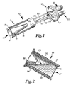
- Figure 1 is a perspective view, partially cut-away, of an MBE effusion cell having a prior art crucible which has a conical configuration.
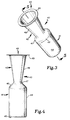
- Figure 2 is a crossectional view of a portion of a dual filament effusion cell having a prior art crucible which has a straight wall, cylindrical body and a conical insert.
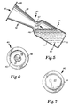
- Figure 3 is a perspective view of an embodiment of the unibody, monolithic negative draft MBE crucible of the present invention.
- Figure 4 is a front view of the crucible shown in Figure 3.
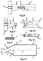
- Figure 5 is crossectional view of the crucible taken along line 5-5 of Figure 3.
- Figure 6 is a top view of the crucible as shown in Figure 4.
- Figure 7 is a bottom view of the crucible.
- Figure 8 is a side view, partially in crossection, of the CVD mandrel assembly used to produce the unibody crucible.
- Figure 9 is a side view, partially in crossection, of the top member of the mandrel assembly.
- Figure 10 is a side view, partially in crossection, of the bottom member of the mandrel assembly.
- Figure 11 is a side view of a center stud member of the mandrel assembly.
- Figure 12 is a side view of a hanger member which is attached to the mandrel assembly to hang it in an operative orientation during CVD.
- Figure 13 is a crossectional view, taken along the center axis, of another embodiment of the unibody, monolithic negative draft MBE crucible of the present invention.
- a typical MBE effusion cell 10 such as one manufactured by EPI MBE Equipment Group of St. Paul, Minnesota USA, generally comprises a head assembly 11 and a mounting flange and support assembly 12.
- the mounting flange and support assembly 12 couples the effusion cell 10 to an MBE growth chamber (not shown).
- the assembly 12 further supports the head assembly 11 at a predetermined position within the growth chamber.
- the mounting flange and support assembly 12 includes a cylindrical sealing flange 21 of a predetermined diameter, and externally oriented screw on-type power and Omega®-type thermocouple connectors 19 and 20, respectively, connected to the flange 21.
- the head assembly 11 includes a centrally interiorly disposed crucible 13 surrounded by a filament 14 and a heat shield 15.
- the filament 14 is preferably constructed of Tantalum with a PBN insulation.
- the heat shield 15 is preferably constructed of multiple layers of high purity Tantalum foil.
- a band-shaped thermocouple 16 is connected to the exterior of the crucible 13 near its base.
- the power conductors 23 are connected to the filament 14 and the thermocouple leads 24 are connected to the thermocouple 16.
- the crucible 13 has a conical configuration with an outwardly oriented orifice 17 of a predetermined diameter with an annular lip 18.
- the crucible 13 is constructed of PBN, for example.
- the effusion cell 10 may include various optional features such as an integral shutter, an integral water cooling system, and the like.
- Figure 2 shows another head assembly structure manufactured by EPI MBE Equipment Group, with an improved, dual filament heating system and an improved, but multi-piece crucible design.
- the heating system includes a first filament 28 for heating the bottom or base region of a crucible 27 and a second filament 29 for heating the top or tip region of the crucible 27.
- the filaments 28 and 29 are independently controlled to permit differential heating of various parts of the crucible 27.
- Heat shielding 30 surrounds the crucible 27 and filaments 28 and 29.
- This dual filament structure permits improved functionality.
- the crucible 27 comprises a cylindrical body 31 and a conical insert 32.
- the cylindrical body 31 has straight or substantially straight walls with little or no positive draft (taper), and no negative draft.
- the walls of the body 31 define a predetermined interior volume which is relatively large compared to that of the conical crucible 13 shown in Figure 1.
- the conical insert 32 has a pronounced positive draft.
- the aforementioned structure provides a "hot lip" configuration which reduces oval defect production.
- the differential heating provided by the dual filaments 28 and 29 minimizes hydrodynamic instability and rapid depletion effect common in other hot lip source designs.
- the design of crucible 27 shown in Figure 2 provides several advantages over the crucible 13 shown in Figure 1, it does have an important limitation. Specifically, the crucible body 31 separates, and insulates to a certain extent, the tip filament 29 from the conical insert 33. This separation is believed to provide less than optimal heating of the insert 33.
- the present invention integrates the structure of the negative draft or taper conical insert into the crucible body to form a unitary crucible body, whereby the tip filament of the dual filament heating system may now be optimally disposed with respect to the tip. Additionally, the size and configuration of the conical section may be optimized.
- the invention further provides a method and apparatus for constructing a monolithic, unibody crucible having a negative draft portion via chemical vapor deposition.
- the crucible 40 generally comprises a base section 41 and a conical section 42 with a first or outer orifice 43 disposed at one end of the conical section 42 and open to the exterior of the crucible 40.
- the base section 41 and conical section 42 form a single, unitary piece.
- the crucible 40 is formed of an inert, corrosion resistant material.
- a preferred material is PBN, such as Pyrosyl® sold by CVD Products, Inc. of Hudson, New Hampshire.
- the preferred thickness of PBN for the crucible 40 is approximately 0.035 inches (0.08 cm.).
- the crucible 40 is constructed via a chemical vapor deposition process set forth in detail below.
- All boundary edges between the base member 41 and conical member 42 elements mentioned below in detail are preferably radius edges.
- the crucible 40 embodiment shown is approximately 5.3 inches(13.4 cm.) in length, although the length and other dimensions may be varied consistent with the basic teachings of this invention.
- the base section 41 has a substantially cylindrical configuration with a side wall 44, a bottom 45 disposed at one end of the side wall 44, and a negative draft tapered wall or neck 46 disposed at the opposite end of the side wall 44.
- the side wall 44 has a predetermined substantially uniform circumference and a predetermined length.
- the diameter of the base section 41 shown is approximately 1.4 inches (3.5 cm.).
- the length base section 41 is approximately 2.9 inches (7.3 cm.).
- the negative draft wall 46 tapers inwardly (laterally) towards the central longitudinal axis (not shown) of the crucible 40 (and hence, the side wall 44) preferably at an angle approximately 45.0 degrees with respect to the longitudinal plane of the exterior of the base section 41.
- the negative draft wall 46 terminates at its outward end to define a second or inner orifice 47.
- the second orifice 47 is a region of smallest diameter in the crucible 40 and is approximately 0.6 inches (1.5 cm.) in this embodiment.
- the conical section 42 is defined by the portion of the crucible extending from the second orifice 47 to the periphery of the first orifice 43.
- the conical section 42 comprises a positive draft wall 48 and an annular lip 49.
- the length of the conical section in this embodiment is approximately 2.3 inches (5.8 cm.).
- the wall 48 tapers outwardly (laterally) away from the central longitudinal axis of the crucible 40 at a preferred approximate angle of 9.0 degrees measured with respect to the central axis.
- the annular lip 49 extends outwardly from the terminal edge of the wall 48 preferably at a right angle thereto.
- the first orifice has a preferred diameter of approximately 1.5 inches (3.8 cm.) in the embodiment shown.
- the annular lip 49 has a width of approximately 0.8 inches (2.0 cm.).
- the crucible 40 is typically oriented upwardly at an angle for MBE.
- An element or compound is added to the crucible and heated by the dual filament system, for example, of an effusion source to form a melt 50.
- the conical section 42 of the crucible 40 yields a level of thickness uniformity which matches that provided by conical crucibles. Additionally though, the design minimizes depletion effects. In all types of cells the beam equivalent pressure at a constant cell temperature decreases over time due to depletion of the source melt material. This effect is greater in cells using conical crucibles because of more rapid reductions in melt surface area in those cells. The effect is further increased in hot lip cells because they are typically somewhat less efficient in their use of material.
- the crucible 40 of this invention virtually eliminates depletion effect by providing a melt surface 51 which is consistent in size (area) and shape.
- the portion of the melt surface 51 "seen" by the substrate is equivalent to the size of the inner orifice 47.
- the distance between the crucible orifice and the melt surface increases and the melt surface area decreases as the melt charge depletes in volume, thus causing them to exhibit depletion effects.
- crucible 40 of this invention is the large crucible volume provided by the straight wall, cylindrical base section 41, which increases useful capacity in comparison to conical crucibles.
- a further advantage is that the inner orifice 47 provided by the integral conical section 42 forms a thermal baffle between melt 50 and the shutter (not shown) improving hydrodynamic stability and reducing shutter-related transients.
- the integrally formed conical section 42 enables optimal positioning of the tip filament of the dual filament heating system to minimize oval defect production.
- the one piece design crucible 90 is cylindrical and generally comprises a base section 91 and a conical section 92, with a first or outer orifice 98 disposed at one end of the conical section 92.
- the crucible 90 is preferably constructed of PBN via a vapor deposition process. This particular crucible 90 embodiment is approximately 8.1 inches(20.5 cm.) in length, 2.9 inches (7.3 cm.) widest diameter at the base 91, and 0.9 inches (2.2 cm.) narrowest diameter at an inner orifice 96.
- the base section 91 has straight side walls 93 and a bottom wall 94 closing one end.
- Tapered wall 95 is disposed at the opposite end of the wall 93 and has a negative draft angle "B" of approximately 30 degrees measured with respect to the axis 99 of the crucible 90.
- Conical section 92 has a tapered wall 97 with a positive draft angle "C" of approximately 15 degrees.
- the conical section 92 has a significantly reduced size (approximately 0.3 inches (0.7 cm.) axial length) in comparison to the conical section 42 of crucible 40 shown in Figures 3-7.
- the unibody design permits construction of a crucible 90 which is essentially a "virtual crucible" in that it has a very small orifice or nozzle and enables placement of the effusion cell shutter very close to the source material or melt.
- the shutter may also be made much smaller because of this.
- the prior art teaches large orifices and requires a cell design wherein the shutter is large and is disposed a greater distance away from the source.
- the crucibles 40 and 90 described above are constructed by chemical vapor deposition.
- Chemical vapor deposition is practiced, for example, by CVD Products. Inc.
- the preferred material for construction of the crucible shown is PBN.
- PBN is produced by introducing gaseous boron trichloride, ammonia and a diluant into a growth chamber at a submillimeter pressure and a temperature of approximately 1800 degrees Celsius (C.). This method may, however, also be used in conjunction with other chemicals to make various materials by chemical vapor deposition.
- the PBN yielded from the reaction of compounds is deposited on a forming mandrel 55.
- the formed structure in this case a crucible, is separated from the mandrel 55 by a process described below.
- the forming mandrel 55 is a four part assembly constructed of graphite. It basically comprises a top member 56, a bottom member 57, and a center stud or nipple 58. The top and bottom member 56 and 57 are separate components which are connected by the center stud 58.
- the forming mandrel 55 is maintained in an operative position by a top stud 59 which is connected to a threaded bore 60 centrally disposed in the top end of the top member 56.
- the bottom member 57 is formed of graphite, preferably a fine grained, high density, pre-purified graphite, and has a hollow, bored out center. Graphite begins to oxidize at approximately 300 degrees C.
- the dimensions of the bottom member 57 are dependent of the dimensions of the crucible to be formed. In the case of the crucible 40, the member 57 is cylindrical and approximately 3.1 inches long and 1.3 inches in diameter.
- the bottom edge 64 of the member 57 has a radius.
- the top edge has a negative draft forming tapered neck 65 of angle "A", preferably 45 degrees. As is best shown in Figure 10 , both ends 66 and 67 of the tapered portion or neck 65, are radiused.
- the diameter of the top end of the neck 65 is preferably approximately 0.58 inches.
- An axial bore 68 in the bottom member 57 is preferably 5/16 inch in diameter and 2 and 7/8 inches deep.
- Axial bore 68 has a threaded upper portion 69, which is 3/4 inches deep and 3/8-16 UNC.
- the top member 56 is also hollow and formed of graphite, preferably a fine grained, high density, pre-purified graphite.
- the dimensions of the top member 56 are also dependent of the dimensions of the crucible to be formed.
- the member 56 is curvilinear with a positive draft forming tapered neck 73 and a lip forming base 74.
- the member 56 taper neck 73 has a length of approximately 2.1 inches, a bottom diameter of approximately 0.58 inches, and a top diameter of approximately 1.4 inches.
- the base 74 has a diameter of 2.8 inches and a thickness of 0.7 inches.
- the junction of the neck 73 and base 74 is preferably radiused.
- An axial bore 75 in the top member 56 is preferably 5/16 inch in diameter and drilled through the entire length of the member 56.
- Axial bore 75 has a threaded upper portion 60, which is 1.0 inch deep and 3/4-10 UNC, and a threaded bottom portion 76 which is 3/4 inches deep and 3/8-16 UNC.
- the center stud 58 is also hollow and constructed of graphite, preferably a fine grained, high density, pre-purified graphite.
- the dimensions of the stud 58 are dependent upon the size and configuration of the crucible formed and in particular upon the dimensions and type of threaded bores 69 and 76 in top and bottom members 56 and 57, respectively.
- the stud 58 preferably has a length of approximately 1.5 inches, a threaded 3/8-16 UNC periphery , and an axial channel 80. 3/16 inches in diameter.
- the stud 58 wall thickness (equal to one half the outside diameter of the stud 58 body minus the bore 80 diameter) is thick enough to enable tightening together of the top and bottom members 56 and 57, and thin enough to allow the stud 58 to break or fracture during cooling in the crucible forming process described below.
- This structure in combination with the type of construction material, yields a stud which will reliably and snugly connect the top and bottom members 56 and 57, and further which will permit the desired break.
- the top or hanger stud 59 is preferably solid and constructed of graphite, preferably a course grained, extruded graphite.
- the dimensions of the stud 59 are dependent upon the size and configuration of the crucible formed and in particular upon the dimensions and type of threaded bore 60 in top and bottom member 56.
- the stud 59 preferably has a length of approximately 4.5 inches and a threaded 3/4-10 UNC periphery.
- the stud 59 has an axial bore 84 in one end which is 3/16 inches in diameter and 1 and 1/2 inches deep.
- a lateral bore 85,1/8 inches in diameter, is disposed in the side of the stud 59 and is communicatively connected to the axial bore 84.
- the left end, as viewed in Figure 12 , of the stud 59 is screwed into aperture 60 of top member 56 a distance such that the lateral bore 85 remains on the exterior of the mandrel 55.
- the bores 84 and 85 provide a venting means for the interior cavities of the mandrel 55.
- the process of manufacturing the crucible of the present invention comprises the following steps. First, the top and bottom member 56 and 57 are mated by screwing them together with the center stud 58. Next, the hanger stud 59 is screwed to the bore 60 of the top member 56. Importantly, the channels 84 and 85 in the hanger stud 59 are oriented to vent pressure in the aligned axial channels 75 and 68 of the assembly 55. The resultant mandrel assembly 55 is placed in a CVD growth chamber. CVD coating of PBN then occurs via a process generally known in the art. After the high temperature growth process is completed, the resultant mandrel/container assembly is cooled.
- the graphite materials of the forming mandrel 55 contract or shrink at a higher rate than does the PBN due to a high difference in thermal contraction coefficients.
- the center stud 58 is designed to fracture. The fracture allows the top and bottom members 56 and 57 of the mandrel 55 to shrink independently inside the PBN shell formed on the outside of the mandrel assembly 55 without damaging it due to longitudinal contraction near the neck region 47 of the crucible 40. After cooling is complete, the assembly is moved to a separate oxidation chamber to remove the bottom member 57.
- An air injector is inserted into the center cavity of the mandrel 55.
- the assembly is heated at a temperature above 300 degrees C., preferably 750 degrees C., for a predetermined period of time, preferably approximately 40 hours, to oxidize the bottom member 57 which is now "inside" base section 41 of the formed PBN crucible 40.
- the flow of air into the heated bottom member 57 is adjusted via the injector to optimize oxidation. Oxidization destroys the bottom member 57, which would otherwise not be able to be removed due to the negative draft angle of the wall 46 of the newly formed crucible base section 41.
- PBN has a higher oxidation temperature, being stable in air up to approximately 1,200 degrees C., it does not oxidize during the heating step of the process.
Landscapes
- Chemical & Material Sciences (AREA)
- Engineering & Computer Science (AREA)
- Materials Engineering (AREA)
- Mechanical Engineering (AREA)
- Organic Chemistry (AREA)
- Metallurgy (AREA)
- Chemical Kinetics & Catalysis (AREA)
- Ceramic Engineering (AREA)
- General Chemical & Material Sciences (AREA)
- General Engineering & Computer Science (AREA)
- Manufacturing & Machinery (AREA)
- Inorganic Chemistry (AREA)
- Structural Engineering (AREA)
- Crystallography & Structural Chemistry (AREA)
- Physical Vapour Deposition (AREA)
- Crystals, And After-Treatments Of Crystals (AREA)
- Physical Deposition Of Substances That Are Components Of Semiconductor Devices (AREA)
- Cookers (AREA)
- Thermally Insulated Containers For Foods (AREA)
- Saccharide Compounds (AREA)
- Chemical Vapour Deposition (AREA)
Priority Applications (1)
| Application Number | Priority Date | Filing Date | Title |
|---|---|---|---|
| EP01126382A EP1215307A3 (en) | 1995-05-03 | 1996-05-03 | Unibody crucible |
Applications Claiming Priority (3)
| Application Number | Priority Date | Filing Date | Title |
|---|---|---|---|
| US08/433,033 US5820681A (en) | 1995-05-03 | 1995-05-03 | Unibody crucible and effusion cell employing such a crucible |
| PCT/US1996/006267 WO1996035091A1 (en) | 1995-05-03 | 1996-05-03 | Unibody crucible |
| US433033 | 2006-05-11 |
Related Child Applications (1)
| Application Number | Title | Priority Date | Filing Date |
|---|---|---|---|
| EP01126382A Division EP1215307A3 (en) | 1995-05-03 | 1996-05-03 | Unibody crucible |
Publications (3)
| Publication Number | Publication Date |
|---|---|
| EP0826131A1 EP0826131A1 (en) | 1998-03-04 |
| EP0826131A4 EP0826131A4 (en) | 1998-07-15 |
| EP0826131B1 true EP0826131B1 (en) | 2002-09-18 |
Family
ID=23718594
Family Applications (2)
| Application Number | Title | Priority Date | Filing Date |
|---|---|---|---|
| EP96915496A Expired - Lifetime EP0826131B1 (en) | 1995-05-03 | 1996-05-03 | Unibody crucible |
| EP01126382A Withdrawn EP1215307A3 (en) | 1995-05-03 | 1996-05-03 | Unibody crucible |
Family Applications After (1)
| Application Number | Title | Priority Date | Filing Date |
|---|---|---|---|
| EP01126382A Withdrawn EP1215307A3 (en) | 1995-05-03 | 1996-05-03 | Unibody crucible |
Country Status (7)
| Country | Link |
|---|---|
| US (3) | US5820681A (2) |
| EP (2) | EP0826131B1 (2) |
| JP (2) | JPH11504613A (2) |
| AT (1) | ATE224525T1 (2) |
| AU (2) | AU5725796A (2) |
| DE (1) | DE69623765T2 (2) |
| WO (2) | WO1996034994A1 (2) |
Families Citing this family (55)
| Publication number | Priority date | Publication date | Assignee | Title |
|---|---|---|---|---|
| JP3212522B2 (ja) * | 1996-12-27 | 2001-09-25 | 信越化学工業株式会社 | 分子線エピタキシー用熱分解窒化硼素るつぼ |
| US6053981A (en) * | 1998-09-15 | 2000-04-25 | Coherent, Inc. | Effusion cell and method of use in molecular beam epitaxy |
| US6202591B1 (en) * | 1998-11-12 | 2001-03-20 | Flex Products, Inc. | Linear aperture deposition apparatus and coating process |
| US6140624A (en) * | 1999-07-02 | 2000-10-31 | Advanced Ceramics Corporation | Pyrolytic boron nitride radiation heater |
| WO2001051160A1 (en) * | 2000-01-12 | 2001-07-19 | Applied Epi, Inc. | Ultra-low temperature effusion cell |
| JP2001220286A (ja) | 2000-02-02 | 2001-08-14 | Sharp Corp | 分子線源および分子線エピタキシ装置 |
| US7194197B1 (en) * | 2000-03-16 | 2007-03-20 | Global Solar Energy, Inc. | Nozzle-based, vapor-phase, plume delivery structure for use in production of thin-film deposition layer |
| US6551405B1 (en) * | 2000-09-22 | 2003-04-22 | The Board Of Trustees Of The University Of Arkansas | Tool and method for in situ vapor phase deposition source material reloading and maintenance |
| DE10056686B4 (de) * | 2000-11-15 | 2005-09-29 | Forschungsverbund Berlin E.V. | Verdampferzelle und ein Verfahren zur Herstellung von Aufdampfschichten |
| JP2003002778A (ja) * | 2001-06-26 | 2003-01-08 | International Manufacturing & Engineering Services Co Ltd | 薄膜堆積用分子線セル |
| US6926920B2 (en) * | 2002-06-11 | 2005-08-09 | Taiwan Semiconductor Manufacturing Co., Ltd | Chemical vapor deposition (CVD) calibration method providing enhanced uniformity |
| JP4344631B2 (ja) * | 2004-03-02 | 2009-10-14 | 長州産業株式会社 | 有機物薄膜堆積用分子線源 |
| US20050232824A1 (en) * | 2004-04-14 | 2005-10-20 | Pangrcic Robert A | High temperature electrolyte testing container |
| US20050229856A1 (en) * | 2004-04-20 | 2005-10-20 | Malik Roger J | Means and method for a liquid metal evaporation source with integral level sensor and external reservoir |
| US7493691B2 (en) * | 2004-05-20 | 2009-02-24 | Honeywell International Inc. | Co-molding metallic-lined phenolic components |
| JP4442558B2 (ja) * | 2005-01-06 | 2010-03-31 | 三星モバイルディスプレイ株式會社 | 蒸発源の加熱制御方法,蒸発源の冷却制御方法および蒸発源の制御方法 |
| JP5009816B2 (ja) * | 2005-02-22 | 2012-08-22 | イー−サイエンス,インコーポレイテッド | 流出セルバルブ |
| US7732737B2 (en) * | 2005-10-11 | 2010-06-08 | Kimberly-Clark Worldwide, Inc. | Micro powered warming container |
| JP4673190B2 (ja) * | 2005-11-01 | 2011-04-20 | 長州産業株式会社 | 薄膜堆積用分子線源とその分子線量制御方法 |
| US20070218199A1 (en) * | 2006-02-13 | 2007-09-20 | Veeco Instruments Inc. | Crucible eliminating line of sight between a source material and a target |
| US8747554B2 (en) * | 2006-06-20 | 2014-06-10 | Momentive Performance Materials Inc. | Multi-piece ceramic crucible and method for making thereof |
| EP1967606A1 (en) * | 2007-03-08 | 2008-09-10 | Applied Materials, Inc. | Evaporation crucible and evaporation apparatus with adapted evaporation characteristic |
| US20090169781A1 (en) * | 2007-12-31 | 2009-07-02 | Marc Schaepkens | Low thermal conductivity low density pyrolytic boron nitride material, method of making, and articles made therefrom |
| US7968353B2 (en) | 2008-04-15 | 2011-06-28 | Global Solar Energy, Inc. | Apparatus and methods for manufacturing thin-film solar cells |
| WO2010019213A2 (en) | 2008-08-11 | 2010-02-18 | Veeco Instruments Inc. | Vacuum deposition sources having heated effusion orifices |
| US8512806B2 (en) * | 2008-08-12 | 2013-08-20 | Momentive Performance Materials Inc. | Large volume evaporation source |
| WO2011065999A1 (en) * | 2008-12-18 | 2011-06-03 | Veeco Instruments Inc. | Linear deposition source |
| US20100282167A1 (en) * | 2008-12-18 | 2010-11-11 | Veeco Instruments Inc. | Linear Deposition Source |
| US20100159132A1 (en) * | 2008-12-18 | 2010-06-24 | Veeco Instruments, Inc. | Linear Deposition Source |
| US9062369B2 (en) * | 2009-03-25 | 2015-06-23 | Veeco Instruments, Inc. | Deposition of high vapor pressure materials |
| WO2011082179A1 (en) * | 2009-12-28 | 2011-07-07 | Global Solar Energy, Inc. | Apparatus and methods of mixing and depositing thin film photovoltaic compositions |
| TWI477646B (zh) * | 2010-08-09 | 2015-03-21 | Hon Hai Prec Ind Co Ltd | 化學氣相沉積設備 |
| JP5720379B2 (ja) | 2011-03-31 | 2015-05-20 | 日本電気株式会社 | 水流発電装置 |
| DE102011121148A1 (de) * | 2011-12-15 | 2013-06-20 | Dr. Eberl Mbe-Komponenten Gmbh | Vorrichtung zum Verdampfen eines Verdampfungsguts |
| DE102011122591A1 (de) * | 2011-12-30 | 2013-07-04 | Dr. Eberl Mbe-Komponenten Gmbh | Vorrichtung zum Verdampfen eines Verdampfungsguts |
| WO2015066428A2 (en) | 2013-11-01 | 2015-05-07 | Bnnt, Llc | Induction-coupled plasma synthesis of boron nitride nanotubes |
| TWI513839B (zh) * | 2013-12-12 | 2015-12-21 | Nat Inst Chung Shan Science & Technology | An apparatus and method for improving sublimation deposition rate |
| JP6374096B2 (ja) | 2014-04-24 | 2018-08-15 | ビイエヌエヌティ・エルエルシイ | 連続的な窒化ホウ素ナノチューブ繊維 |
| CA2968358C (en) | 2014-11-01 | 2022-10-18 | Bnnt, Llc | Target holders, multiple-incidence angle, and multizone heating for bnnt synthesis |
| WO2016100715A1 (en) | 2014-12-17 | 2016-06-23 | Bnnt, Llc | Boron nitride nanotube enhanced electrical components |
| EP3295216B1 (en) | 2015-05-13 | 2022-10-12 | Bnnt, Llc | Boron nitride nanotube neutron detector |
| JP6705837B2 (ja) | 2015-05-21 | 2020-06-03 | ビイエヌエヌティ・エルエルシイ | 直接誘導による窒化ホウ素ナノチューブ合成 |
| JP6488400B2 (ja) * | 2015-07-13 | 2019-03-20 | アプライド マテリアルズ インコーポレイテッドApplied Materials,Incorporated | 蒸発源 |
| EP3427269B1 (en) | 2016-03-08 | 2023-07-26 | TerraPower LLC | Fission product getter |
| TWI737718B (zh) | 2016-04-25 | 2021-09-01 | 美商創新先進材料股份有限公司 | 含有瀉流源的沉積系統及相關方法 |
| WO2018044370A2 (en) | 2016-05-20 | 2018-03-08 | Terrapower, Llc | Sodium-cesium vapor trap system and method |
| CN207038182U (zh) | 2017-03-29 | 2018-02-23 | 泰拉能源有限责任公司 | 铯收集器 |
| JP7078462B2 (ja) * | 2018-06-13 | 2022-05-31 | 株式会社アルバック | 真空蒸着装置用の蒸着源 |
| WO2019239192A1 (en) * | 2018-06-15 | 2019-12-19 | Arcelormittal | Vacuum deposition facility and method for coating a substrate |
| KR102910316B1 (ko) * | 2019-08-23 | 2026-01-08 | 테라파워, 엘엘씨 | 나트륨 기화기 및 나트륨 기화기의 사용 방법 |
| WO2021077100A1 (en) * | 2019-10-17 | 2021-04-22 | Veeco Instruments Inc. | Molecular beam epitaxy systems with variable substrate-to-source arrangements |
| US12480853B2 (en) * | 2021-09-28 | 2025-11-25 | University Of Central Florida Research Foundation, Inc. | Crucibles for thermogravimetric analysis (TGA) |
| WO2024006828A1 (en) * | 2022-06-28 | 2024-01-04 | Cornell University | Reduction of surface oxidation in molecular beam epitaxy sources |
| EP4555539A1 (en) | 2022-07-13 | 2025-05-21 | TerraPower, LLC | Oxidation of cesium as method for removing cesium vapor from cover gas in nuclear reactors |
| CN119085320B (zh) * | 2024-11-06 | 2025-05-02 | 苏州焜原光电有限公司 | 一种测温坩埚组件及测温方法 |
Family Cites Families (23)
| Publication number | Priority date | Publication date | Assignee | Title |
|---|---|---|---|---|
| US464680A (en) * | 1891-12-08 | Wind-wheel | ||
| FR1164034A (fr) * | 1956-12-27 | 1958-10-06 | Perfectionnements aux creusets pour le dépôt de couches métallisées | |
| US3467583A (en) * | 1966-05-16 | 1969-09-16 | Camin Lab | Process for making a hollow body with protective inner layer for high-temperature applications |
| US4035460A (en) * | 1972-05-16 | 1977-07-12 | Siemens Aktiengesellschaft | Shaped bodies and production of semiconductor material |
| US4217855A (en) * | 1974-10-23 | 1980-08-19 | Futaba Denshi Kogyo K.K. | Vaporized-metal cluster ion source and ionized-cluster beam deposition device |
| USD282894S (en) | 1983-10-11 | 1986-03-11 | General Foods Corporation | Cruet |
| USD295145S (en) | 1984-09-17 | 1988-04-12 | Maison Paul Jeanjean | Carafe |
| US4646680A (en) * | 1985-12-23 | 1987-03-03 | General Electric Company | Crucible for use in molecular beam epitaxial processing |
| FR2598721B1 (fr) * | 1986-05-15 | 1988-09-30 | Commissariat Energie Atomique | Cellule pour epitaxie par jets moleculaires et procede associe |
| JPS6353259A (ja) * | 1986-08-22 | 1988-03-07 | Mitsubishi Electric Corp | 薄膜形成方法 |
| US4856457A (en) * | 1987-02-20 | 1989-08-15 | Hughes Aircraft Company | Cluster source for nonvolatile species, having independent temperature control |
| US4833319A (en) * | 1987-02-27 | 1989-05-23 | Hughes Aircraft Company | Carrier gas cluster source for thermally conditioned clusters |
| JPH01153595A (ja) * | 1987-12-09 | 1989-06-15 | Nec Corp | 分子線発生装置 |
| US5034604A (en) * | 1989-08-29 | 1991-07-23 | Board Of Regents, The University Of Texas System | Refractory effusion cell to generate a reproducible, uniform and ultra-pure molecular beam of elemental molecules, utilizing reduced thermal gradient filament construction |
| JP2619068B2 (ja) * | 1989-09-08 | 1997-06-11 | 三菱電機株式会社 | 薄膜形成装置 |
| US5032366A (en) * | 1990-04-30 | 1991-07-16 | Union Carbide Coatings Service Technology Corporation | Boron nitride boat and process for producing it |
| US5158750A (en) * | 1990-06-06 | 1992-10-27 | Praxair S.T. Technology, Inc. | Boron nitride crucible |
| JPH04274316A (ja) * | 1991-02-28 | 1992-09-30 | Mitsubishi Electric Corp | 分子線エピタキシー用セル |
| JPH05294787A (ja) * | 1992-04-22 | 1993-11-09 | Mitsubishi Electric Corp | 結晶成長方法及びその装置 |
| DE4225169C2 (de) * | 1992-07-30 | 1994-09-22 | Juergen Dipl Phys Dr Gspann | Vorrichtung und Verfahren zur Erzeugung von Agglomeratstrahlen |
| US5453233A (en) * | 1993-04-05 | 1995-09-26 | Cvd, Inc. | Method of producing domes of ZNS and ZNSE via a chemical vapor deposition technique |
| JP3369643B2 (ja) * | 1993-07-01 | 2003-01-20 | 信越化学工業株式会社 | 熱分解窒化ほう素成形体の製造方法 |
| JP2595894B2 (ja) * | 1994-04-26 | 1997-04-02 | 日本電気株式会社 | 水素ラジカル発生装置 |
-
1995
- 1995-05-03 US US08/433,033 patent/US5820681A/en not_active Expired - Lifetime
-
1996
- 1996-05-03 AU AU57257/96A patent/AU5725796A/en not_active Abandoned
- 1996-05-03 EP EP96915496A patent/EP0826131B1/en not_active Expired - Lifetime
- 1996-05-03 DE DE69623765T patent/DE69623765T2/de not_active Expired - Lifetime
- 1996-05-03 EP EP01126382A patent/EP1215307A3/en not_active Withdrawn
- 1996-05-03 AT AT96915496T patent/ATE224525T1/de not_active IP Right Cessation
- 1996-05-03 AU AU56367/96A patent/AU5636796A/en not_active Abandoned
- 1996-05-03 WO PCT/US1996/006223 patent/WO1996034994A1/en not_active Ceased
- 1996-05-03 JP JP8533541A patent/JPH11504613A/ja active Pending
- 1996-05-03 WO PCT/US1996/006267 patent/WO1996035091A1/en not_active Ceased
- 1996-10-31 US US08/741,921 patent/US5800753A/en not_active Expired - Lifetime
-
1997
- 1997-03-12 US US08/816,166 patent/US5932294A/en not_active Expired - Lifetime
-
2010
- 2010-12-06 JP JP2010271283A patent/JP5174137B2/ja not_active Expired - Lifetime
Also Published As
| Publication number | Publication date |
|---|---|
| EP0826131A4 (en) | 1998-07-15 |
| US5820681A (en) | 1998-10-13 |
| JP2011079736A (ja) | 2011-04-21 |
| JPH11504613A (ja) | 1999-04-27 |
| DE69623765D1 (de) | 2002-10-24 |
| AU5725796A (en) | 1996-11-21 |
| WO1996034994A1 (en) | 1996-11-07 |
| US5932294A (en) | 1999-08-03 |
| DE69623765T2 (de) | 2003-07-17 |
| WO1996035091A1 (en) | 1996-11-07 |
| AU5636796A (en) | 1996-11-21 |
| ATE224525T1 (de) | 2002-10-15 |
| EP1215307A2 (en) | 2002-06-19 |
| EP0826131A1 (en) | 1998-03-04 |
| EP1215307A3 (en) | 2002-09-04 |
| JP5174137B2 (ja) | 2013-04-03 |
| US5800753A (en) | 1998-09-01 |
Similar Documents
| Publication | Publication Date | Title |
|---|---|---|
| US5932294A (en) | MBE deposition method employing effusion cell having a unibody crucible | |
| US5827371A (en) | Unibody crucible and effusion source employing such a crucible | |
| US5158750A (en) | Boron nitride crucible | |
| US11661671B2 (en) | Technique for controlling temperature uniformity in crystal growth apparatus | |
| US5976263A (en) | Sources used in molecular beam epitaxy | |
| EP0865518B1 (en) | A device for heat treatment of objects | |
| US20080026591A1 (en) | Sintered metal components for crystal growth reactors | |
| KR101435676B1 (ko) | 여러 단편으로 된 세라믹 도가니 및 그의 제조방법 | |
| JP2001114599A (ja) | 単結晶製造方法及び単結晶製造装置 | |
| EP0460943A1 (en) | Boron nitride crucible and its production | |
| US20010004875A1 (en) | Device and method for producing at least one SiC single crystal | |
| US5698168A (en) | Unibody gas plasma source technology | |
| US6670282B2 (en) | Method and apparatus for producing silicon carbide crystal | |
| CN119710929A (zh) | 碳化硅晶体生长坩埚、籽晶及晶体生长方法 | |
| US5551977A (en) | Susceptor for EFG crystal growth apparatus | |
| JPH1160375A (ja) | 分子線エピタキシー用分子線源ルツボ | |
| JPH05319981A (ja) | 分子線エピタキシー用セル | |
| JP2005053729A (ja) | 薄膜堆積用分子線源用るつぼ | |
| JPS61292314A (ja) | 分子線結晶成長装置 | |
| JPH07331418A (ja) | 真空蒸着装置および真空蒸着方法 |
Legal Events
| Date | Code | Title | Description |
|---|---|---|---|
| PUAI | Public reference made under article 153(3) epc to a published international application that has entered the european phase |
Free format text: ORIGINAL CODE: 0009012 |
|
| 17P | Request for examination filed |
Effective date: 19971201 |
|
| AK | Designated contracting states |
Kind code of ref document: A1 Designated state(s): AT BE CH DE DK ES FI FR GB GR IE IT LI LU MC NL PT SE |
|
| A4 | Supplementary search report drawn up and despatched |
Effective date: 19980602 |
|
| AK | Designated contracting states |
Kind code of ref document: A4 Designated state(s): AT BE CH DE DK ES FI FR GB GR IE IT LI LU MC NL PT SE |
|
| 17Q | First examination report despatched |
Effective date: 19991228 |
|
| GRAG | Despatch of communication of intention to grant |
Free format text: ORIGINAL CODE: EPIDOS AGRA |
|
| GRAG | Despatch of communication of intention to grant |
Free format text: ORIGINAL CODE: EPIDOS AGRA |
|
| GRAG | Despatch of communication of intention to grant |
Free format text: ORIGINAL CODE: EPIDOS AGRA |
|
| GRAH | Despatch of communication of intention to grant a patent |
Free format text: ORIGINAL CODE: EPIDOS IGRA |
|
| GRAG | Despatch of communication of intention to grant |
Free format text: ORIGINAL CODE: EPIDOS AGRA |
|
| GRAH | Despatch of communication of intention to grant a patent |
Free format text: ORIGINAL CODE: EPIDOS IGRA |
|
| RAP1 | Party data changed (applicant data changed or rights of an application transferred) |
Owner name: APPLIED EPI, INC. |
|
| GRAA | (expected) grant |
Free format text: ORIGINAL CODE: 0009210 |
|
| AK | Designated contracting states |
Kind code of ref document: B1 Designated state(s): AT BE CH DE DK ES FI FR GB GR IE IT LI LU MC NL PT SE |
|
| PG25 | Lapsed in a contracting state [announced via postgrant information from national office to epo] |
Ref country code: NL Free format text: LAPSE BECAUSE OF FAILURE TO SUBMIT A TRANSLATION OF THE DESCRIPTION OR TO PAY THE FEE WITHIN THE PRESCRIBED TIME-LIMIT Effective date: 20020918 Ref country code: IT Free format text: LAPSE BECAUSE OF FAILURE TO SUBMIT A TRANSLATION OF THE DESCRIPTION OR TO PAY THE FEE WITHIN THE PRESCRIBED TIME-LIMIT;WARNING: LAPSES OF ITALIAN PATENTS WITH EFFECTIVE DATE BEFORE 2007 MAY HAVE OCCURRED AT ANY TIME BEFORE 2007. THE CORRECT EFFECTIVE DATE MAY BE DIFFERENT FROM THE ONE RECORDED. Effective date: 20020918 Ref country code: GR Free format text: LAPSE BECAUSE OF FAILURE TO SUBMIT A TRANSLATION OF THE DESCRIPTION OR TO PAY THE FEE WITHIN THE PRESCRIBED TIME-LIMIT Effective date: 20020918 Ref country code: BE Free format text: LAPSE BECAUSE OF FAILURE TO SUBMIT A TRANSLATION OF THE DESCRIPTION OR TO PAY THE FEE WITHIN THE PRESCRIBED TIME-LIMIT Effective date: 20020918 Ref country code: AT Free format text: LAPSE BECAUSE OF FAILURE TO SUBMIT A TRANSLATION OF THE DESCRIPTION OR TO PAY THE FEE WITHIN THE PRESCRIBED TIME-LIMIT Effective date: 20020918 |
|
| REF | Corresponds to: |
Ref document number: 224525 Country of ref document: AT Date of ref document: 20021015 Kind code of ref document: T |
|
| REG | Reference to a national code |
Ref country code: GB Ref legal event code: FG4D |
|
| REG | Reference to a national code |
Ref country code: CH Ref legal event code: EP |
|
| REG | Reference to a national code |
Ref country code: CH Ref legal event code: NV Representative=s name: MOINAS & SAVOYE SA |
|
| REG | Reference to a national code |
Ref country code: IE Ref legal event code: FG4D |
|
| REF | Corresponds to: |
Ref document number: 69623765 Country of ref document: DE Date of ref document: 20021024 |
|
| ET | Fr: translation filed | ||
| PG25 | Lapsed in a contracting state [announced via postgrant information from national office to epo] |
Ref country code: SE Free format text: LAPSE BECAUSE OF FAILURE TO SUBMIT A TRANSLATION OF THE DESCRIPTION OR TO PAY THE FEE WITHIN THE PRESCRIBED TIME-LIMIT Effective date: 20021218 Ref country code: DK Free format text: LAPSE BECAUSE OF FAILURE TO SUBMIT A TRANSLATION OF THE DESCRIPTION OR TO PAY THE FEE WITHIN THE PRESCRIBED TIME-LIMIT Effective date: 20021218 |
|
| PG25 | Lapsed in a contracting state [announced via postgrant information from national office to epo] |
Ref country code: PT Free format text: LAPSE BECAUSE OF FAILURE TO SUBMIT A TRANSLATION OF THE DESCRIPTION OR TO PAY THE FEE WITHIN THE PRESCRIBED TIME-LIMIT Effective date: 20021219 |
|
| NLV1 | Nl: lapsed or annulled due to failure to fulfill the requirements of art. 29p and 29m of the patents act | ||
| PG25 | Lapsed in a contracting state [announced via postgrant information from national office to epo] |
Ref country code: ES Free format text: LAPSE BECAUSE OF FAILURE TO SUBMIT A TRANSLATION OF THE DESCRIPTION OR TO PAY THE FEE WITHIN THE PRESCRIBED TIME-LIMIT Effective date: 20030328 |
|
| PG25 | Lapsed in a contracting state [announced via postgrant information from national office to epo] |
Ref country code: LU Free format text: LAPSE BECAUSE OF NON-PAYMENT OF DUE FEES Effective date: 20030503 |
|
| PG25 | Lapsed in a contracting state [announced via postgrant information from national office to epo] |
Ref country code: IE Free format text: LAPSE BECAUSE OF NON-PAYMENT OF DUE FEES Effective date: 20030505 |
|
| PG25 | Lapsed in a contracting state [announced via postgrant information from national office to epo] |
Ref country code: MC Free format text: LAPSE BECAUSE OF NON-PAYMENT OF DUE FEES Effective date: 20030531 |
|
| PLBE | No opposition filed within time limit |
Free format text: ORIGINAL CODE: 0009261 |
|
| STAA | Information on the status of an ep patent application or granted ep patent |
Free format text: STATUS: NO OPPOSITION FILED WITHIN TIME LIMIT |
|
| 26N | No opposition filed |
Effective date: 20030619 |
|
| REG | Reference to a national code |
Ref country code: IE Ref legal event code: MM4A |
|
| REG | Reference to a national code |
Ref country code: FR Ref legal event code: PLFP Year of fee payment: 20 |
|
| PGFP | Annual fee paid to national office [announced via postgrant information from national office to epo] |
Ref country code: FI Payment date: 20150507 Year of fee payment: 20 Ref country code: GB Payment date: 20150424 Year of fee payment: 20 Ref country code: DE Payment date: 20150601 Year of fee payment: 20 Ref country code: CH Payment date: 20150428 Year of fee payment: 20 |
|
| PGFP | Annual fee paid to national office [announced via postgrant information from national office to epo] |
Ref country code: FR Payment date: 20150424 Year of fee payment: 20 |
|
| REG | Reference to a national code |
Ref country code: DE Ref legal event code: R071 Ref document number: 69623765 Country of ref document: DE |
|
| REG | Reference to a national code |
Ref country code: CH Ref legal event code: PL |
|
| REG | Reference to a national code |
Ref country code: GB Ref legal event code: PE20 Expiry date: 20160502 |
|
| PG25 | Lapsed in a contracting state [announced via postgrant information from national office to epo] |
Ref country code: GB Free format text: LAPSE BECAUSE OF EXPIRATION OF PROTECTION Effective date: 20160502 |