EP0826544A1 - Système combiné d'entraínement à moteur électrique et moteur à combustion interne - Google Patents
Système combiné d'entraínement à moteur électrique et moteur à combustion interne Download PDFInfo
- Publication number
- EP0826544A1 EP0826544A1 EP96306388A EP96306388A EP0826544A1 EP 0826544 A1 EP0826544 A1 EP 0826544A1 EP 96306388 A EP96306388 A EP 96306388A EP 96306388 A EP96306388 A EP 96306388A EP 0826544 A1 EP0826544 A1 EP 0826544A1
- Authority
- EP
- European Patent Office
- Prior art keywords
- electrical machine
- engine
- clutch
- load
- drive
- Prior art date
- Legal status (The legal status is an assumption and is not a legal conclusion. Google has not performed a legal analysis and makes no representation as to the accuracy of the status listed.)
- Granted
Links
Images

Classifications
-
- B—PERFORMING OPERATIONS; TRANSPORTING
- B60—VEHICLES IN GENERAL
- B60K—ARRANGEMENT OR MOUNTING OF PROPULSION UNITS OR OF TRANSMISSIONS IN VEHICLES; ARRANGEMENT OR MOUNTING OF PLURAL DIVERSE PRIME-MOVERS IN VEHICLES; AUXILIARY DRIVES FOR VEHICLES; INSTRUMENTATION OR DASHBOARDS FOR VEHICLES; ARRANGEMENTS IN CONNECTION WITH COOLING, AIR INTAKE, GAS EXHAUST OR FUEL SUPPLY OF PROPULSION UNITS IN VEHICLES
- B60K6/00—Arrangement or mounting of plural diverse prime-movers for mutual or common propulsion, e.g. hybrid propulsion systems comprising electric motors and internal combustion engines
- B60K6/20—Arrangement or mounting of plural diverse prime-movers for mutual or common propulsion, e.g. hybrid propulsion systems comprising electric motors and internal combustion engines the prime-movers consisting of electric motors and internal combustion engines, e.g. HEVs
- B60K6/22—Arrangement or mounting of plural diverse prime-movers for mutual or common propulsion, e.g. hybrid propulsion systems comprising electric motors and internal combustion engines the prime-movers consisting of electric motors and internal combustion engines, e.g. HEVs characterised by apparatus, components or means specially adapted for HEVs
- B60K6/26—Arrangement or mounting of plural diverse prime-movers for mutual or common propulsion, e.g. hybrid propulsion systems comprising electric motors and internal combustion engines the prime-movers consisting of electric motors and internal combustion engines, e.g. HEVs characterised by apparatus, components or means specially adapted for HEVs characterised by the motors or the generators
-
- B—PERFORMING OPERATIONS; TRANSPORTING
- B60—VEHICLES IN GENERAL
- B60W—CONJOINT CONTROL OF VEHICLE SUB-UNITS OF DIFFERENT TYPE OR DIFFERENT FUNCTION; CONTROL SYSTEMS SPECIALLY ADAPTED FOR HYBRID VEHICLES; ROAD VEHICLE DRIVE CONTROL SYSTEMS FOR PURPOSES NOT RELATED TO THE CONTROL OF A PARTICULAR SUB-UNIT
- B60W20/00—Control systems specially adapted for hybrid vehicles
- B60W20/40—Controlling the engagement or disengagement of prime movers, e.g. for transition between prime movers
-
- B—PERFORMING OPERATIONS; TRANSPORTING
- B60—VEHICLES IN GENERAL
- B60K—ARRANGEMENT OR MOUNTING OF PROPULSION UNITS OR OF TRANSMISSIONS IN VEHICLES; ARRANGEMENT OR MOUNTING OF PLURAL DIVERSE PRIME-MOVERS IN VEHICLES; AUXILIARY DRIVES FOR VEHICLES; INSTRUMENTATION OR DASHBOARDS FOR VEHICLES; ARRANGEMENTS IN CONNECTION WITH COOLING, AIR INTAKE, GAS EXHAUST OR FUEL SUPPLY OF PROPULSION UNITS IN VEHICLES
- B60K6/00—Arrangement or mounting of plural diverse prime-movers for mutual or common propulsion, e.g. hybrid propulsion systems comprising electric motors and internal combustion engines
- B60K6/20—Arrangement or mounting of plural diverse prime-movers for mutual or common propulsion, e.g. hybrid propulsion systems comprising electric motors and internal combustion engines the prime-movers consisting of electric motors and internal combustion engines, e.g. HEVs
- B60K6/22—Arrangement or mounting of plural diverse prime-movers for mutual or common propulsion, e.g. hybrid propulsion systems comprising electric motors and internal combustion engines the prime-movers consisting of electric motors and internal combustion engines, e.g. HEVs characterised by apparatus, components or means specially adapted for HEVs
- B60K6/38—Arrangement or mounting of plural diverse prime-movers for mutual or common propulsion, e.g. hybrid propulsion systems comprising electric motors and internal combustion engines the prime-movers consisting of electric motors and internal combustion engines, e.g. HEVs characterised by apparatus, components or means specially adapted for HEVs characterised by the driveline clutches
-
- B—PERFORMING OPERATIONS; TRANSPORTING
- B60—VEHICLES IN GENERAL
- B60K—ARRANGEMENT OR MOUNTING OF PROPULSION UNITS OR OF TRANSMISSIONS IN VEHICLES; ARRANGEMENT OR MOUNTING OF PLURAL DIVERSE PRIME-MOVERS IN VEHICLES; AUXILIARY DRIVES FOR VEHICLES; INSTRUMENTATION OR DASHBOARDS FOR VEHICLES; ARRANGEMENTS IN CONNECTION WITH COOLING, AIR INTAKE, GAS EXHAUST OR FUEL SUPPLY OF PROPULSION UNITS IN VEHICLES
- B60K6/00—Arrangement or mounting of plural diverse prime-movers for mutual or common propulsion, e.g. hybrid propulsion systems comprising electric motors and internal combustion engines
- B60K6/20—Arrangement or mounting of plural diverse prime-movers for mutual or common propulsion, e.g. hybrid propulsion systems comprising electric motors and internal combustion engines the prime-movers consisting of electric motors and internal combustion engines, e.g. HEVs
- B60K6/22—Arrangement or mounting of plural diverse prime-movers for mutual or common propulsion, e.g. hybrid propulsion systems comprising electric motors and internal combustion engines the prime-movers consisting of electric motors and internal combustion engines, e.g. HEVs characterised by apparatus, components or means specially adapted for HEVs
- B60K6/38—Arrangement or mounting of plural diverse prime-movers for mutual or common propulsion, e.g. hybrid propulsion systems comprising electric motors and internal combustion engines the prime-movers consisting of electric motors and internal combustion engines, e.g. HEVs characterised by apparatus, components or means specially adapted for HEVs characterised by the driveline clutches
- B60K6/387—Actuated clutches, i.e. clutches engaged or disengaged by electric, hydraulic or mechanical actuating means
-
- B—PERFORMING OPERATIONS; TRANSPORTING
- B60—VEHICLES IN GENERAL
- B60K—ARRANGEMENT OR MOUNTING OF PROPULSION UNITS OR OF TRANSMISSIONS IN VEHICLES; ARRANGEMENT OR MOUNTING OF PLURAL DIVERSE PRIME-MOVERS IN VEHICLES; AUXILIARY DRIVES FOR VEHICLES; INSTRUMENTATION OR DASHBOARDS FOR VEHICLES; ARRANGEMENTS IN CONNECTION WITH COOLING, AIR INTAKE, GAS EXHAUST OR FUEL SUPPLY OF PROPULSION UNITS IN VEHICLES
- B60K6/00—Arrangement or mounting of plural diverse prime-movers for mutual or common propulsion, e.g. hybrid propulsion systems comprising electric motors and internal combustion engines
- B60K6/20—Arrangement or mounting of plural diverse prime-movers for mutual or common propulsion, e.g. hybrid propulsion systems comprising electric motors and internal combustion engines the prime-movers consisting of electric motors and internal combustion engines, e.g. HEVs
- B60K6/22—Arrangement or mounting of plural diverse prime-movers for mutual or common propulsion, e.g. hybrid propulsion systems comprising electric motors and internal combustion engines the prime-movers consisting of electric motors and internal combustion engines, e.g. HEVs characterised by apparatus, components or means specially adapted for HEVs
- B60K6/40—Arrangement or mounting of plural diverse prime-movers for mutual or common propulsion, e.g. hybrid propulsion systems comprising electric motors and internal combustion engines the prime-movers consisting of electric motors and internal combustion engines, e.g. HEVs characterised by apparatus, components or means specially adapted for HEVs characterised by the assembly or relative disposition of components
-
- B—PERFORMING OPERATIONS; TRANSPORTING
- B60—VEHICLES IN GENERAL
- B60K—ARRANGEMENT OR MOUNTING OF PROPULSION UNITS OR OF TRANSMISSIONS IN VEHICLES; ARRANGEMENT OR MOUNTING OF PLURAL DIVERSE PRIME-MOVERS IN VEHICLES; AUXILIARY DRIVES FOR VEHICLES; INSTRUMENTATION OR DASHBOARDS FOR VEHICLES; ARRANGEMENTS IN CONNECTION WITH COOLING, AIR INTAKE, GAS EXHAUST OR FUEL SUPPLY OF PROPULSION UNITS IN VEHICLES
- B60K6/00—Arrangement or mounting of plural diverse prime-movers for mutual or common propulsion, e.g. hybrid propulsion systems comprising electric motors and internal combustion engines
- B60K6/20—Arrangement or mounting of plural diverse prime-movers for mutual or common propulsion, e.g. hybrid propulsion systems comprising electric motors and internal combustion engines the prime-movers consisting of electric motors and internal combustion engines, e.g. HEVs
- B60K6/42—Arrangement or mounting of plural diverse prime-movers for mutual or common propulsion, e.g. hybrid propulsion systems comprising electric motors and internal combustion engines the prime-movers consisting of electric motors and internal combustion engines, e.g. HEVs characterised by the architecture of the hybrid electric vehicle
- B60K6/48—Parallel type
-
- B—PERFORMING OPERATIONS; TRANSPORTING
- B60—VEHICLES IN GENERAL
- B60K—ARRANGEMENT OR MOUNTING OF PROPULSION UNITS OR OF TRANSMISSIONS IN VEHICLES; ARRANGEMENT OR MOUNTING OF PLURAL DIVERSE PRIME-MOVERS IN VEHICLES; AUXILIARY DRIVES FOR VEHICLES; INSTRUMENTATION OR DASHBOARDS FOR VEHICLES; ARRANGEMENTS IN CONNECTION WITH COOLING, AIR INTAKE, GAS EXHAUST OR FUEL SUPPLY OF PROPULSION UNITS IN VEHICLES
- B60K6/00—Arrangement or mounting of plural diverse prime-movers for mutual or common propulsion, e.g. hybrid propulsion systems comprising electric motors and internal combustion engines
- B60K6/20—Arrangement or mounting of plural diverse prime-movers for mutual or common propulsion, e.g. hybrid propulsion systems comprising electric motors and internal combustion engines the prime-movers consisting of electric motors and internal combustion engines, e.g. HEVs
- B60K6/50—Architecture of the driveline characterised by arrangement or kind of transmission units
- B60K6/54—Transmission for changing ratio
-
- B—PERFORMING OPERATIONS; TRANSPORTING
- B60—VEHICLES IN GENERAL
- B60L—PROPULSION OF ELECTRICALLY-PROPELLED VEHICLES; SUPPLYING ELECTRIC POWER FOR AUXILIARY EQUIPMENT OF ELECTRICALLY-PROPELLED VEHICLES; ELECTRODYNAMIC BRAKE SYSTEMS FOR VEHICLES IN GENERAL; MAGNETIC SUSPENSION OR LEVITATION FOR VEHICLES; MONITORING OPERATING VARIABLES OF ELECTRICALLY-PROPELLED VEHICLES; ELECTRIC SAFETY DEVICES FOR ELECTRICALLY-PROPELLED VEHICLES
- B60L50/00—Electric propulsion with power supplied within the vehicle
- B60L50/10—Electric propulsion with power supplied within the vehicle using propulsion power supplied by engine-driven generators, e.g. generators driven by combustion engines
- B60L50/15—Electric propulsion with power supplied within the vehicle using propulsion power supplied by engine-driven generators, e.g. generators driven by combustion engines with additional electric power supply
-
- B—PERFORMING OPERATIONS; TRANSPORTING
- B60—VEHICLES IN GENERAL
- B60W—CONJOINT CONTROL OF VEHICLE SUB-UNITS OF DIFFERENT TYPE OR DIFFERENT FUNCTION; CONTROL SYSTEMS SPECIALLY ADAPTED FOR HYBRID VEHICLES; ROAD VEHICLE DRIVE CONTROL SYSTEMS FOR PURPOSES NOT RELATED TO THE CONTROL OF A PARTICULAR SUB-UNIT
- B60W10/00—Conjoint control of vehicle sub-units of different type or different function
- B60W10/02—Conjoint control of vehicle sub-units of different type or different function including control of driveline clutches
-
- B—PERFORMING OPERATIONS; TRANSPORTING
- B60—VEHICLES IN GENERAL
- B60W—CONJOINT CONTROL OF VEHICLE SUB-UNITS OF DIFFERENT TYPE OR DIFFERENT FUNCTION; CONTROL SYSTEMS SPECIALLY ADAPTED FOR HYBRID VEHICLES; ROAD VEHICLE DRIVE CONTROL SYSTEMS FOR PURPOSES NOT RELATED TO THE CONTROL OF A PARTICULAR SUB-UNIT
- B60W10/00—Conjoint control of vehicle sub-units of different type or different function
- B60W10/04—Conjoint control of vehicle sub-units of different type or different function including control of propulsion units
- B60W10/06—Conjoint control of vehicle sub-units of different type or different function including control of propulsion units including control of combustion engines
-
- B—PERFORMING OPERATIONS; TRANSPORTING
- B60—VEHICLES IN GENERAL
- B60W—CONJOINT CONTROL OF VEHICLE SUB-UNITS OF DIFFERENT TYPE OR DIFFERENT FUNCTION; CONTROL SYSTEMS SPECIALLY ADAPTED FOR HYBRID VEHICLES; ROAD VEHICLE DRIVE CONTROL SYSTEMS FOR PURPOSES NOT RELATED TO THE CONTROL OF A PARTICULAR SUB-UNIT
- B60W10/00—Conjoint control of vehicle sub-units of different type or different function
- B60W10/04—Conjoint control of vehicle sub-units of different type or different function including control of propulsion units
- B60W10/08—Conjoint control of vehicle sub-units of different type or different function including control of propulsion units including control of electric propulsion units, e.g. motors or generators
-
- B—PERFORMING OPERATIONS; TRANSPORTING
- B60—VEHICLES IN GENERAL
- B60W—CONJOINT CONTROL OF VEHICLE SUB-UNITS OF DIFFERENT TYPE OR DIFFERENT FUNCTION; CONTROL SYSTEMS SPECIALLY ADAPTED FOR HYBRID VEHICLES; ROAD VEHICLE DRIVE CONTROL SYSTEMS FOR PURPOSES NOT RELATED TO THE CONTROL OF A PARTICULAR SUB-UNIT
- B60W10/00—Conjoint control of vehicle sub-units of different type or different function
- B60W10/18—Conjoint control of vehicle sub-units of different type or different function including control of braking systems
-
- B—PERFORMING OPERATIONS; TRANSPORTING
- B60—VEHICLES IN GENERAL
- B60W—CONJOINT CONTROL OF VEHICLE SUB-UNITS OF DIFFERENT TYPE OR DIFFERENT FUNCTION; CONTROL SYSTEMS SPECIALLY ADAPTED FOR HYBRID VEHICLES; ROAD VEHICLE DRIVE CONTROL SYSTEMS FOR PURPOSES NOT RELATED TO THE CONTROL OF A PARTICULAR SUB-UNIT
- B60W10/00—Conjoint control of vehicle sub-units of different type or different function
- B60W10/24—Conjoint control of vehicle sub-units of different type or different function including control of energy storage means
- B60W10/26—Conjoint control of vehicle sub-units of different type or different function including control of energy storage means for electrical energy, e.g. batteries or capacitors
-
- B—PERFORMING OPERATIONS; TRANSPORTING
- B60—VEHICLES IN GENERAL
- B60W—CONJOINT CONTROL OF VEHICLE SUB-UNITS OF DIFFERENT TYPE OR DIFFERENT FUNCTION; CONTROL SYSTEMS SPECIALLY ADAPTED FOR HYBRID VEHICLES; ROAD VEHICLE DRIVE CONTROL SYSTEMS FOR PURPOSES NOT RELATED TO THE CONTROL OF A PARTICULAR SUB-UNIT
- B60W20/00—Control systems specially adapted for hybrid vehicles
-
- Y—GENERAL TAGGING OF NEW TECHNOLOGICAL DEVELOPMENTS; GENERAL TAGGING OF CROSS-SECTIONAL TECHNOLOGIES SPANNING OVER SEVERAL SECTIONS OF THE IPC; TECHNICAL SUBJECTS COVERED BY FORMER USPC CROSS-REFERENCE ART COLLECTIONS [XRACs] AND DIGESTS
- Y02—TECHNOLOGIES OR APPLICATIONS FOR MITIGATION OR ADAPTATION AGAINST CLIMATE CHANGE
- Y02T—CLIMATE CHANGE MITIGATION TECHNOLOGIES RELATED TO TRANSPORTATION
- Y02T10/00—Road transport of goods or passengers
- Y02T10/60—Other road transportation technologies with climate change mitigation effect
- Y02T10/62—Hybrid vehicles
-
- Y—GENERAL TAGGING OF NEW TECHNOLOGICAL DEVELOPMENTS; GENERAL TAGGING OF CROSS-SECTIONAL TECHNOLOGIES SPANNING OVER SEVERAL SECTIONS OF THE IPC; TECHNICAL SUBJECTS COVERED BY FORMER USPC CROSS-REFERENCE ART COLLECTIONS [XRACs] AND DIGESTS
- Y02—TECHNOLOGIES OR APPLICATIONS FOR MITIGATION OR ADAPTATION AGAINST CLIMATE CHANGE
- Y02T—CLIMATE CHANGE MITIGATION TECHNOLOGIES RELATED TO TRANSPORTATION
- Y02T10/00—Road transport of goods or passengers
- Y02T10/60—Other road transportation technologies with climate change mitigation effect
- Y02T10/70—Energy storage systems for electromobility, e.g. batteries
-
- Y—GENERAL TAGGING OF NEW TECHNOLOGICAL DEVELOPMENTS; GENERAL TAGGING OF CROSS-SECTIONAL TECHNOLOGIES SPANNING OVER SEVERAL SECTIONS OF THE IPC; TECHNICAL SUBJECTS COVERED BY FORMER USPC CROSS-REFERENCE ART COLLECTIONS [XRACs] AND DIGESTS
- Y02—TECHNOLOGIES OR APPLICATIONS FOR MITIGATION OR ADAPTATION AGAINST CLIMATE CHANGE
- Y02T—CLIMATE CHANGE MITIGATION TECHNOLOGIES RELATED TO TRANSPORTATION
- Y02T10/00—Road transport of goods or passengers
- Y02T10/60—Other road transportation technologies with climate change mitigation effect
- Y02T10/7072—Electromobility specific charging systems or methods for batteries, ultracapacitors, supercapacitors or double-layer capacitors
Definitions
- the present invention relates to a engine and electrical machine coupled through a clutch and control component.
- the present invention is accordingly a unique combined driving structure made up of an electrical machine and an engine (or other rotational power devices) coupled through an eccentric clutch and an electrical machine control component to achieve the following working conditions in response to operation of a manual operating interface, a central controller and a drive control device:
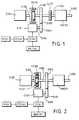
- Figure 1 is a schematic drawing of a first preferred embodiment.
- Figure 2 is a schematic drawing of a second preferred embodiment.
- Figure 3 is a schematic drawing of a third preferred embodiment.
- Figure 4 is a schematic drawing of a fourth preferred embodiment.
- Figure 5 is a schematic drawing of a fifth preferred embodiment.
- An electrical machine E101 is combined with the first gear G101 and is controlled by a manual operating interface M101, central controller CCU101, and drive control device D101 to cause the electrical machine E101 to be powered by a battery BAT101 in order to provide a motor output for driving the gear G101 as follows:
- the gear G101 is rotated at high speed to drive the eccentric clutch FC101 to close and start the engine IC101, whereupon the engine IC101 either drives the load directly or through the speed reducing device GB101, while electrical machine E101 is either powered to drive the load with the engine IC101 together or the power to the electrical machine can be cut off to cause the electrical machine to be in a waiting state, or the electrical machine can be driven by the engine IC101 to be operated as a generator to charge the battery BAT101 or supply power to other loads.
- the electrical machine E101 may be either a permanent magnet or a winding excited, variable frequency driven field type electrical device, or a brushed alternator type electrical device, with its armature winding being commonly connected via conducting rings for AC output and commutators for DC input/output, and whereby the AC output can be a variable frequency output or a constant frequency output through the engine constant speed control.
- the load feedback may be used to drive the engine IC101 to provide a friction damping brake and the electrical machine E101 used for regeneration feedback braking functions
- the electrical machine may be operated as a motor to drive the load
- the electrical machine may be operated as a generator to a provide braking function by recovering the kinetic energy to the battery, or to supply power to the other loads to provide the braking function.
- table 1 shows the operating states of engine IC101 and gear direction (clockwise (CW) or counterclockwise (CCW)) engine speed (Stop, 0 ⁇ Max (running speed), and Max ⁇ 0 (deceleration)), battery status (charge/discharge), electric machine operation (motor/generator), and clutch status (open/close) during the various functions selectable by manual control M101 and controller CCU101 as described above.
- FIG. 2 illustrates the second preferred embodiment of the invention in which the eccentric clutch set FC101, FC102 and the second gear G102 are installed between the drive shaft S103 of the engine IC101 and the load driving output shaft S104, wherein the output shaft S104 can be provided either to drive the load directly or to drive the load through the reducing gear train GB201.
- the second gear G102 is engaged with the first gear G101, or the illustrated gear train can be replaced by a multiple staged speed reducer or other transmission components such as chain wheels, and the electrical machine E101 is combined with the first gear G101 and is controlled by the manual operating interface M101, central controller CCU101 and the drive control device D101 to be powered by the battery BAT101 to drive the gear G101.
- Electric machine E101 is again equipped with AC power generating functions and includes a permanent magnet, winding excited, variable frequency driven field type electrical device, or a brushed alternator type electrical device, with its armature winding commonly connected to conducting rings for AC output and to commutators for DC input/output, so that the AC output can be a variable frequency output or a constant frequency output through the engine constant speed control.
- the double acting eccentric clutch set of this embodiment is constituted by the two eccentric clutches FC101 and FC102 embodied either in a sleeve joint structure or in a common structure, and is incorporated in a three layer structure including an inner layer, a middle layer and an external layer.
- the inner layer is provided with a drive friction disk to act outwardly when the eccentric force reaches a preset value and is combined with the output shaft for mutual driving.
- the middle layer is combined with the engine and is provided with an inner ring friction coupling surface while its outside is provided with a drive friction disk to act outwardly when the eccentric force reaches a preset value thereby to be friction coupled with the inner ring of the external layer to constitute an output clutch function, and the external layer structure is further combined with the engine for temporally releasing the linkage between the engine and the load when the engine is operated at a low speed.
- This embodiment is controlled by the central controller CCU101, manual operating interface M101, electrical machine drive device D101, and the battery BAT101 to provide the following functions:
- Table 2 which gives the specific operating states for the functions described above.
- Table 2 is identical to Figure 1, except that the status of both clutches FC101 and FC102 is given in this table.
- FIG 3 shows the third preferred embodiment of the invention, in which an output clutch CL301 is further installed between the second gear G102 and the output shaft S102 driven by the inner and external rings of the double acting eccentric clutch FC101, FC102, identical to that of the embodiment illustrated in Figure 2, and the output shaft S105 for driving the load or the speed reducing mechanism, to thereby link or separate the two output shafts.
- the clutch CL301 is driven manually or by electromagnetic or fluid power, and when it is closed, this embodiment has the same functions as are described above in connection with the second preferred embodiment.
- this embodiment has the following additional function of generation at stand-still, in which the engine IC101 drives the middle layer and the external layer of the double acting clutch FC101, FC102 to be coupled, thereby to driving the electrical machine E101 to be operated as a generator to charge the battery or supply power to other loads, in which case the power generation can be further controlled by timing or capacity.
- Electric machine E101 is again comprised of a permanent magnet or a winding excited, variable frequency driven field type electrical device, or a brushed alternator type electrical device, in which its armature winding is commonly connected to conducting rings for AC output and to commutators for DC input/output, and whereby the AC output can be a variable frequency output or a constant frequency output through the engine constant speed control.
- Table 3 gives the specific operating states of the various system components for each of the functions described above in connection with the third preferred embodiment of the invention. This table differs from Table 2 in its inclusion of operating states for clutch CL301.
- Figure 4 illustrates the fourth preferred embodiment of the invention, in which the output shafts of the electrical machine E101 and the engine IC101 are embodied in a common shaft structure, while the double acting clutch FC101, FC102 is installed between the electrical machine E101 and the engine IC101 and has its inner layer and external layer coupled with the common shaft S101 of the electrical machine E101 and the output shaft S104, while its middle layer is coupled with the engine rotating shaft S103, and the operation types include the following:
- FIG. 5 shows the fifth preferred embodiment of the invention, in which a clutch CL101 is further installed between the output shaft S104 and the loading shaft S105 described in connection with the embodiment of Figure 4, and the clutch is driven manually or by electromagnetic or fluid power, such that when it is closed, the combined system has the same functions as the fourth embodiments, and when the clutch CL101 is released, the combined system has the additional function of generation at stand-still, in which the engine IC101 drives the middle layer and the external layer of the double acting clutch FC101, FC102 to be coupled, to thereby further drive the electrical machine E101 to be operated as a generator to charge the battery BAT101 or supply power to other loads, with the electrical machine E101 being selected to be comprised of a permanent magnet or a winding excited, variable frequency driven field type electrical device, or a brushed alternator type electrical device, with its armature winding commonly connected to a conducting rings for
Landscapes
- Engineering & Computer Science (AREA)
- Combustion & Propulsion (AREA)
- Transportation (AREA)
- Mechanical Engineering (AREA)
- Chemical & Material Sciences (AREA)
- Power Engineering (AREA)
- Automation & Control Theory (AREA)
- Hybrid Electric Vehicles (AREA)
- Electric Propulsion And Braking For Vehicles (AREA)
- Control Of Vehicle Engines Or Engines For Specific Uses (AREA)
- Output Control And Ontrol Of Special Type Engine (AREA)
- Lock And Its Accessories (AREA)
- Connection Of Motors, Electrical Generators, Mechanical Devices, And The Like (AREA)
- Arrangement Of Transmissions (AREA)
- One-Way And Automatic Clutches, And Combinations Of Different Clutches (AREA)
- Auxiliary Drives, Propulsion Controls, And Safety Devices (AREA)
- Control Of Multiple Motors (AREA)
Priority Applications (8)
| Application Number | Priority Date | Filing Date | Title |
|---|---|---|---|
| EP96306388A EP0826544B1 (fr) | 1996-09-03 | 1996-09-03 | Système combiné d'entraínement à moteur électrique et moteur à combustion interne |
| AT96306388T ATE209118T1 (de) | 1996-09-03 | 1996-09-03 | Kombiniertes antriebssystem mit kraftmaschine und elektrischer maschine |
| ES96306388T ES2168443T3 (es) | 1996-09-03 | 1996-09-03 | Sistema de accionamiento combinado que comprende una maquina electrica y un motor de combustion interna. |
| DE69617225T DE69617225T2 (de) | 1996-09-03 | 1996-09-03 | Kombiniertes Antriebssystem mit Kraftmaschine und elektrischer Maschine |
| CA002184673A CA2184673C (fr) | 1996-09-03 | 1996-09-03 | Groupe de production d'energie a machine electrique entrainee par un moteur |
| AU64490/96A AU723142B2 (en) | 1996-09-03 | 1996-09-05 | The driving electrical machine speed controlled power combined system and device |
| JP26815696A JP3650491B2 (ja) | 1996-09-03 | 1996-10-09 | 駆動電気機械の速度制御による複合動力装置 |
| BRPI9604416-0A BR9604416B1 (pt) | 1996-09-03 | 1996-10-17 | dispositivo e motor elÉtricos combinados. |
Applications Claiming Priority (5)
| Application Number | Priority Date | Filing Date | Title |
|---|---|---|---|
| EP96306388A EP0826544B1 (fr) | 1996-09-03 | 1996-09-03 | Système combiné d'entraínement à moteur électrique et moteur à combustion interne |
| CA002184673A CA2184673C (fr) | 1996-09-03 | 1996-09-03 | Groupe de production d'energie a machine electrique entrainee par un moteur |
| AU64490/96A AU723142B2 (en) | 1996-09-03 | 1996-09-05 | The driving electrical machine speed controlled power combined system and device |
| JP26815696A JP3650491B2 (ja) | 1996-09-03 | 1996-10-09 | 駆動電気機械の速度制御による複合動力装置 |
| BRPI9604416-0A BR9604416B1 (pt) | 1996-09-03 | 1996-10-17 | dispositivo e motor elÉtricos combinados. |
Publications (2)
| Publication Number | Publication Date |
|---|---|
| EP0826544A1 true EP0826544A1 (fr) | 1998-03-04 |
| EP0826544B1 EP0826544B1 (fr) | 2001-11-21 |
Family
ID=27507156
Family Applications (1)
| Application Number | Title | Priority Date | Filing Date |
|---|---|---|---|
| EP96306388A Expired - Lifetime EP0826544B1 (fr) | 1996-09-03 | 1996-09-03 | Système combiné d'entraínement à moteur électrique et moteur à combustion interne |
Country Status (8)
| Country | Link |
|---|---|
| EP (1) | EP0826544B1 (fr) |
| JP (1) | JP3650491B2 (fr) |
| AT (1) | ATE209118T1 (fr) |
| AU (1) | AU723142B2 (fr) |
| BR (1) | BR9604416B1 (fr) |
| CA (1) | CA2184673C (fr) |
| DE (1) | DE69617225T2 (fr) |
| ES (1) | ES2168443T3 (fr) |
Cited By (5)
| Publication number | Priority date | Publication date | Assignee | Title |
|---|---|---|---|---|
| EP1449699A1 (fr) | 2003-02-20 | 2004-08-25 | Tai-Her Yang | Système de propulsion hybride avec unités dynamo-électriques |
| GB2447274A (en) * | 2007-03-06 | 2008-09-10 | Graeme Eric Hawksley | Hybrid propulsion system |
| CN104859444A (zh) * | 2014-12-31 | 2015-08-26 | 张明 | 一种利用车辆行使的惯性动能致自身发电的车辆 |
| CN108674199A (zh) * | 2018-06-11 | 2018-10-19 | 周伟 | 电动汽车的增程式动力装置 |
| DE102019212476A1 (de) * | 2019-08-21 | 2021-02-25 | Zf Friedrichshafen Ag | Antriebssystem |
Families Citing this family (8)
| Publication number | Priority date | Publication date | Assignee | Title |
|---|---|---|---|---|
| JP4755048B2 (ja) * | 2006-08-10 | 2011-08-24 | ヤマハ発動機株式会社 | ハイブリッド式自動二輪車 |
| JP4755039B2 (ja) * | 2006-07-25 | 2011-08-24 | ヤマハ発動機株式会社 | ハイブリッド式自動二輪車 |
| JP5218835B2 (ja) * | 2008-09-18 | 2013-06-26 | アイシン精機株式会社 | 車両用駆動装置 |
| CN103777530B (zh) * | 2012-11-08 | 2017-02-15 | 北京中科信电子装备有限公司 | 一种直流电源输出换向系统 |
| CN103287277B (zh) * | 2013-04-28 | 2017-05-31 | 淄博正邦知识产权企划有限公司 | 一种高续航能力的电动交通工具 |
| CN103986381B (zh) * | 2014-05-28 | 2016-06-15 | 东南大学 | 海浪发电系统的微网构建最优化功率因数复合控制方法 |
| CN110293833A (zh) * | 2019-07-11 | 2019-10-01 | 宿州市鑫尧健康科技有限公司 | 一种混合动力装置 |
| CN113335120B (zh) * | 2021-08-05 | 2021-11-12 | 深圳市易电创新科技有限公司 | 一种可定时断电的防漏电充电桩 |
Citations (4)
| Publication number | Priority date | Publication date | Assignee | Title |
|---|---|---|---|---|
| US4533011A (en) * | 1979-10-27 | 1985-08-06 | Volkswagenwerk Aktiengesellschaft | Hybrid drive for a vehicle, in particular an automobile |
| WO1993023263A1 (fr) * | 1992-05-08 | 1993-11-25 | Field Bruce F | Vehicule electrique hybride |
| US5343970A (en) * | 1992-09-21 | 1994-09-06 | Severinsky Alex J | Hybrid electric vehicle |
| EP0724978A1 (fr) * | 1995-02-03 | 1996-08-07 | FICHTEL & SACHS AG | Propulsion hybride parallèle pour un véhicule à moteur |
Family Cites Families (2)
| Publication number | Priority date | Publication date | Assignee | Title |
|---|---|---|---|---|
| US5193634A (en) * | 1990-03-08 | 1993-03-16 | Piaggio Veicoli Europei S.P.A. | Hybrid propulsion system for vehicles, in particular for road vehicles |
| US5301764A (en) * | 1992-04-13 | 1994-04-12 | Gardner Conrad O | Hybrid motor vehicle having an electric motor and utilizing an internal combustion engine for fast charge during cruise mode off condition |
-
1996
- 1996-09-03 EP EP96306388A patent/EP0826544B1/fr not_active Expired - Lifetime
- 1996-09-03 CA CA002184673A patent/CA2184673C/fr not_active Expired - Fee Related
- 1996-09-03 DE DE69617225T patent/DE69617225T2/de not_active Expired - Lifetime
- 1996-09-03 ES ES96306388T patent/ES2168443T3/es not_active Expired - Lifetime
- 1996-09-03 AT AT96306388T patent/ATE209118T1/de not_active IP Right Cessation
- 1996-09-05 AU AU64490/96A patent/AU723142B2/en not_active Ceased
- 1996-10-09 JP JP26815696A patent/JP3650491B2/ja not_active Expired - Fee Related
- 1996-10-17 BR BRPI9604416-0A patent/BR9604416B1/pt not_active IP Right Cessation
Patent Citations (4)
| Publication number | Priority date | Publication date | Assignee | Title |
|---|---|---|---|---|
| US4533011A (en) * | 1979-10-27 | 1985-08-06 | Volkswagenwerk Aktiengesellschaft | Hybrid drive for a vehicle, in particular an automobile |
| WO1993023263A1 (fr) * | 1992-05-08 | 1993-11-25 | Field Bruce F | Vehicule electrique hybride |
| US5343970A (en) * | 1992-09-21 | 1994-09-06 | Severinsky Alex J | Hybrid electric vehicle |
| EP0724978A1 (fr) * | 1995-02-03 | 1996-08-07 | FICHTEL & SACHS AG | Propulsion hybride parallèle pour un véhicule à moteur |
Cited By (8)
| Publication number | Priority date | Publication date | Assignee | Title |
|---|---|---|---|---|
| EP1449699A1 (fr) | 2003-02-20 | 2004-08-25 | Tai-Her Yang | Système de propulsion hybride avec unités dynamo-électriques |
| EP2272702A2 (fr) | 2003-02-20 | 2011-01-12 | Yang Tai-Her | Système de propulsion hybride avec unités dynamo-électriques |
| EP2272702A3 (fr) * | 2003-02-20 | 2011-06-08 | Tai-Her Yang | Système de propulsion hybride avec unités dynamo-électriques |
| GB2447274A (en) * | 2007-03-06 | 2008-09-10 | Graeme Eric Hawksley | Hybrid propulsion system |
| GB2447274B (en) * | 2007-03-06 | 2011-05-25 | Hybrid Marine International Ltd | A marine vessel propulsion system, control apparatus & method therefor |
| CN104859444A (zh) * | 2014-12-31 | 2015-08-26 | 张明 | 一种利用车辆行使的惯性动能致自身发电的车辆 |
| CN108674199A (zh) * | 2018-06-11 | 2018-10-19 | 周伟 | 电动汽车的增程式动力装置 |
| DE102019212476A1 (de) * | 2019-08-21 | 2021-02-25 | Zf Friedrichshafen Ag | Antriebssystem |
Also Published As
| Publication number | Publication date |
|---|---|
| EP0826544B1 (fr) | 2001-11-21 |
| ATE209118T1 (de) | 2001-12-15 |
| JP3650491B2 (ja) | 2005-05-18 |
| AU6449096A (en) | 1998-03-12 |
| AU723142B2 (en) | 2000-08-17 |
| BR9604416B1 (pt) | 2009-01-13 |
| DE69617225T2 (de) | 2002-05-08 |
| ES2168443T3 (es) | 2002-06-16 |
| JPH10122006A (ja) | 1998-05-12 |
| DE69617225D1 (de) | 2002-01-03 |
| CA2184673C (fr) | 2007-05-22 |
| BR9604416A (pt) | 1998-06-16 |
| CA2184673A1 (fr) | 1998-03-04 |
Similar Documents
| Publication | Publication Date | Title |
|---|---|---|
| US5644200A (en) | Driving electrical machine speed controlled power combined system and device | |
| EP0806314B1 (fr) | Transmission hybride avec régulation de mode de conduite parmi des embrayages | |
| EP0806315B1 (fr) | Transmission hybride utilisant un électromoteur pour l'entraínement différentiel d'une charge distribuée | |
| CN101809325B (zh) | 具有高效纯电动模式的混合动力系 | |
| EP0806316B1 (fr) | Système de distribution d'une puissance combinée utilisant un différentiel | |
| KR101495354B1 (ko) | 차동 생성 파워 분배 시스템 | |
| CN102009590B (zh) | 具有三档变速功能的电力无级变速器及其动力驱动方法 | |
| CN101314325B (zh) | 混合动力车驱动系统 | |
| EP0826544B1 (fr) | Système combiné d'entraínement à moteur électrique et moteur à combustion interne | |
| CN101318460B (zh) | 混合动力汽车动力总成 | |
| JP2005312295A (ja) | 直列・並列混合式二動力駆動系統 | |
| CN108909431B (zh) | 一种车辆的单电机混合动力驱动系统及控制方法 | |
| JP2008149877A (ja) | エンジンの定速運転を変速制御可能な装置と結合する動力システム | |
| CN108340766B (zh) | 混合动力系统、车辆及其控制方法 | |
| CN204895102U (zh) | 一种转矩耦合和转速耦合动力系统 | |
| CN110758083A (zh) | 一种新能源车辆动力系统及其控制方法 | |
| US20070213158A1 (en) | Drive Train for a Motor Vehicle and Control Method Thereof | |
| CN201291754Y (zh) | 一种混合动力驱动系统 | |
| CN101879857B (zh) | 混合动力系统 | |
| KR100443731B1 (ko) | 다기능복합동력장치 | |
| JP3595627B2 (ja) | 多機能複合動力装置 | |
| CN109305029B (zh) | 混合动力系统及控制方法 | |
| JP3710201B2 (ja) | 異なる組合せの複合動力分配装置 | |
| CN101683816A (zh) | 一种混合动力驱动系统及其驱动方法 | |
| TWI487633B (zh) | 差動發電動力分配裝置及系統 |
Legal Events
| Date | Code | Title | Description |
|---|---|---|---|
| PUAI | Public reference made under article 153(3) epc to a published international application that has entered the european phase |
Free format text: ORIGINAL CODE: 0009012 |
|
| AK | Designated contracting states |
Kind code of ref document: A1 Designated state(s): AT BE CH DE DK ES FI FR GB GR IE IT LI |
|
| AX | Request for extension of the european patent |
Free format text: AL;LT;LV;SI |
|
| 17P | Request for examination filed |
Effective date: 19980703 |
|
| AKX | Designation fees paid |
Free format text: AT BE CH DE DK ES FI FR GB GR IE IT LI |
|
| RBV | Designated contracting states (corrected) |
Designated state(s): AT BE CH DE DK ES FI FR GB GR IE IT LI |
|
| 17Q | First examination report despatched |
Effective date: 19990226 |
|
| GRAG | Despatch of communication of intention to grant |
Free format text: ORIGINAL CODE: EPIDOS AGRA |
|
| GRAG | Despatch of communication of intention to grant |
Free format text: ORIGINAL CODE: EPIDOS AGRA |
|
| GRAH | Despatch of communication of intention to grant a patent |
Free format text: ORIGINAL CODE: EPIDOS IGRA |
|
| GRAH | Despatch of communication of intention to grant a patent |
Free format text: ORIGINAL CODE: EPIDOS IGRA |
|
| GRAA | (expected) grant |
Free format text: ORIGINAL CODE: 0009210 |
|
| AK | Designated contracting states |
Kind code of ref document: B1 Designated state(s): AT BE CH DE DK ES FR GB IE IT LI NL SE |
|
| PG25 | Lapsed in a contracting state [announced via postgrant information from national office to epo] |
Ref country code: BE Free format text: LAPSE BECAUSE OF FAILURE TO SUBMIT A TRANSLATION OF THE DESCRIPTION OR TO PAY THE FEE WITHIN THE PRESCRIBED TIME-LIMIT Effective date: 20011121 Ref country code: AT Free format text: LAPSE BECAUSE OF FAILURE TO SUBMIT A TRANSLATION OF THE DESCRIPTION OR TO PAY THE FEE WITHIN THE PRESCRIBED TIME-LIMIT Effective date: 20011121 |
|
| REF | Corresponds to: |
Ref document number: 209118 Country of ref document: AT Date of ref document: 20011215 Kind code of ref document: T |
|
| REG | Reference to a national code |
Ref country code: CH Ref legal event code: EP |
|
| REG | Reference to a national code |
Ref country code: IE Ref legal event code: FG4D |
|
| REG | Reference to a national code |
Ref country code: GB Ref legal event code: IF02 |
|
| REF | Corresponds to: |
Ref document number: 69617225 Country of ref document: DE Date of ref document: 20020103 |
|
| REG | Reference to a national code |
Ref country code: CH Ref legal event code: NV Representative=s name: KELLER & PARTNER PATENTANWAELTE AG |
|
| PG25 | Lapsed in a contracting state [announced via postgrant information from national office to epo] |
Ref country code: SE Free format text: LAPSE BECAUSE OF FAILURE TO SUBMIT A TRANSLATION OF THE DESCRIPTION OR TO PAY THE FEE WITHIN THE PRESCRIBED TIME-LIMIT Effective date: 20020221 Ref country code: DK Free format text: LAPSE BECAUSE OF FAILURE TO SUBMIT A TRANSLATION OF THE DESCRIPTION OR TO PAY THE FEE WITHIN THE PRESCRIBED TIME-LIMIT Effective date: 20020221 |
|
| ET | Fr: translation filed | ||
| REG | Reference to a national code |
Ref country code: ES Ref legal event code: FG2A Ref document number: 2168443 Country of ref document: ES Kind code of ref document: T3 |
|
| PG25 | Lapsed in a contracting state [announced via postgrant information from national office to epo] |
Ref country code: IE Free format text: LAPSE BECAUSE OF NON-PAYMENT OF DUE FEES Effective date: 20020903 |
|
| PLBE | No opposition filed within time limit |
Free format text: ORIGINAL CODE: 0009261 |
|
| STAA | Information on the status of an ep patent application or granted ep patent |
Free format text: STATUS: NO OPPOSITION FILED WITHIN TIME LIMIT |
|
| 26N | No opposition filed | ||
| REG | Reference to a national code |
Ref country code: IE Ref legal event code: MM4A |
|
| PGFP | Annual fee paid to national office [announced via postgrant information from national office to epo] |
Ref country code: GB Payment date: 20040928 Year of fee payment: 9 Ref country code: ES Payment date: 20040928 Year of fee payment: 9 |
|
| PGFP | Annual fee paid to national office [announced via postgrant information from national office to epo] |
Ref country code: CH Payment date: 20041019 Year of fee payment: 9 |
|
| PG25 | Lapsed in a contracting state [announced via postgrant information from national office to epo] |
Ref country code: IT Free format text: LAPSE BECAUSE OF NON-PAYMENT OF DUE FEES;WARNING: LAPSES OF ITALIAN PATENTS WITH EFFECTIVE DATE BEFORE 2007 MAY HAVE OCCURRED AT ANY TIME BEFORE 2007. THE CORRECT EFFECTIVE DATE MAY BE DIFFERENT FROM THE ONE RECORDED. Effective date: 20050903 Ref country code: GB Free format text: LAPSE BECAUSE OF NON-PAYMENT OF DUE FEES Effective date: 20050903 |
|
| PG25 | Lapsed in a contracting state [announced via postgrant information from national office to epo] |
Ref country code: ES Free format text: LAPSE BECAUSE OF NON-PAYMENT OF DUE FEES Effective date: 20050905 |
|
| PG25 | Lapsed in a contracting state [announced via postgrant information from national office to epo] |
Ref country code: LI Free format text: LAPSE BECAUSE OF NON-PAYMENT OF DUE FEES Effective date: 20050930 Ref country code: CH Free format text: LAPSE BECAUSE OF NON-PAYMENT OF DUE FEES Effective date: 20050930 |
|
| REG | Reference to a national code |
Ref country code: CH Ref legal event code: PL |
|
| GBPC | Gb: european patent ceased through non-payment of renewal fee |
Effective date: 20050903 |
|
| REG | Reference to a national code |
Ref country code: ES Ref legal event code: FD2A Effective date: 20050905 |
|
| PGFP | Annual fee paid to national office [announced via postgrant information from national office to epo] |
Ref country code: NL Payment date: 20070930 Year of fee payment: 12 |
|
| PG25 | Lapsed in a contracting state [announced via postgrant information from national office to epo] |
Ref country code: NL Free format text: LAPSE BECAUSE OF NON-PAYMENT OF DUE FEES Effective date: 20090401 |
|
| NLV4 | Nl: lapsed or anulled due to non-payment of the annual fee |
Effective date: 20090401 |
|
| PGRI | Patent reinstated in contracting state [announced from national office to epo] |
Ref country code: IT Effective date: 20091201 |
|
| PGFP | Annual fee paid to national office [announced via postgrant information from national office to epo] |
Ref country code: FR Payment date: 20101011 Year of fee payment: 15 |
|
| PGFP | Annual fee paid to national office [announced via postgrant information from national office to epo] |
Ref country code: IT Payment date: 20100928 Year of fee payment: 15 |
|
| PG25 | Lapsed in a contracting state [announced via postgrant information from national office to epo] |
Ref country code: IT Free format text: LAPSE BECAUSE OF NON-PAYMENT OF DUE FEES Effective date: 20110903 |
|
| REG | Reference to a national code |
Ref country code: FR Ref legal event code: ST Effective date: 20120531 |
|
| PG25 | Lapsed in a contracting state [announced via postgrant information from national office to epo] |
Ref country code: FR Free format text: LAPSE BECAUSE OF NON-PAYMENT OF DUE FEES Effective date: 20110930 |
|
| PGFP | Annual fee paid to national office [announced via postgrant information from national office to epo] |
Ref country code: DE Payment date: 20140328 Year of fee payment: 18 |
|
| REG | Reference to a national code |
Ref country code: DE Ref legal event code: R119 Ref document number: 69617225 Country of ref document: DE |
|
| REG | Reference to a national code |
Ref country code: DE Ref legal event code: R079 Ref document number: 69617225 Country of ref document: DE Free format text: PREVIOUS MAIN CLASS: B60K0006040000 Ipc: B60K0006000000 |
|
| PG25 | Lapsed in a contracting state [announced via postgrant information from national office to epo] |
Ref country code: DE Free format text: LAPSE BECAUSE OF NON-PAYMENT OF DUE FEES Effective date: 20150401 |