EP0826837A1 - Elément pour installation sanitaire - Google Patents
Elément pour installation sanitaire Download PDFInfo
- Publication number
- EP0826837A1 EP0826837A1 EP97112651A EP97112651A EP0826837A1 EP 0826837 A1 EP0826837 A1 EP 0826837A1 EP 97112651 A EP97112651 A EP 97112651A EP 97112651 A EP97112651 A EP 97112651A EP 0826837 A1 EP0826837 A1 EP 0826837A1
- Authority
- EP
- European Patent Office
- Prior art keywords
- element according
- installation element
- molded body
- elements
- fastening
- Prior art date
- Legal status (The legal status is an assumption and is not a legal conclusion. Google has not performed a legal analysis and makes no representation as to the accuracy of the status listed.)
- Granted
Links
- 238000009434 installation Methods 0.000 title claims description 65
- 239000011810 insulating material Substances 0.000 claims abstract description 3
- 238000009413 insulation Methods 0.000 claims description 9
- 239000004033 plastic Substances 0.000 claims description 4
- 229920003023 plastic Polymers 0.000 claims description 4
- 239000004793 Polystyrene Substances 0.000 claims description 2
- 238000003780 insertion Methods 0.000 claims description 2
- 230000037431 insertion Effects 0.000 claims description 2
- 229920002223 polystyrene Polymers 0.000 claims description 2
- 238000009428 plumbing Methods 0.000 abstract description 3
- XLYOFNOQVPJJNP-UHFFFAOYSA-N water Substances O XLYOFNOQVPJJNP-UHFFFAOYSA-N 0.000 abstract description 3
- 238000010521 absorption reaction Methods 0.000 abstract 1
- 238000004079 fireproofing Methods 0.000 abstract 1
- 238000004519 manufacturing process Methods 0.000 description 8
- 238000000465 moulding Methods 0.000 description 5
- 239000011358 absorbing material Substances 0.000 description 4
- 230000008901 benefit Effects 0.000 description 3
- 239000002184 metal Substances 0.000 description 3
- 150000001875 compounds Chemical class 0.000 description 2
- 238000013461 design Methods 0.000 description 2
- 230000000694 effects Effects 0.000 description 2
- 239000000463 material Substances 0.000 description 2
- 238000000034 method Methods 0.000 description 2
- 239000004570 mortar (masonry) Substances 0.000 description 2
- 239000000725 suspension Substances 0.000 description 2
- 238000012549 training Methods 0.000 description 2
- 239000000853 adhesive Substances 0.000 description 1
- 230000001070 adhesive effect Effects 0.000 description 1
- 238000009833 condensation Methods 0.000 description 1
- 230000005494 condensation Effects 0.000 description 1
- 238000010276 construction Methods 0.000 description 1
- -1 density Substances 0.000 description 1
- 238000009826 distribution Methods 0.000 description 1
- 238000005538 encapsulation Methods 0.000 description 1
- 229920006248 expandable polystyrene Polymers 0.000 description 1
- 230000002349 favourable effect Effects 0.000 description 1
- 238000005187 foaming Methods 0.000 description 1
- 238000005304 joining Methods 0.000 description 1
- 230000007246 mechanism Effects 0.000 description 1
- 239000002557 mineral fiber Substances 0.000 description 1
- 239000000203 mixture Substances 0.000 description 1
- 239000011505 plaster Substances 0.000 description 1
- 230000008569 process Effects 0.000 description 1
- 238000012545 processing Methods 0.000 description 1
- 230000003716 rejuvenation Effects 0.000 description 1
- 230000008439 repair process Effects 0.000 description 1
- 239000007779 soft material Substances 0.000 description 1
- 230000007704 transition Effects 0.000 description 1
Images




Classifications
-
- E—FIXED CONSTRUCTIONS
- E03—WATER SUPPLY; SEWERAGE
- E03D—WATER-CLOSETS OR URINALS WITH FLUSHING DEVICES; FLUSHING VALVES THEREFOR
- E03D11/00—Other component parts of water-closets, e.g. noise-reducing means in the flushing system, flushing pipes mounted in the bowl, seals for the bowl outlet, devices preventing overflow of the bowl contents; devices forming a water seal in the bowl after flushing, devices eliminating obstructions in the bowl outlet or preventing backflow of water and excrements from the waterpipe
- E03D11/13—Parts or details of bowls; Special adaptations of pipe joints or couplings for use with bowls, e.g. provisions in bowl construction preventing backflow of waste-water from the bowl in the flushing pipe or cistern, provisions for a secondary flushing, for noise-reducing
- E03D11/14—Means for connecting the bowl to the wall, e.g. to a wall outlet
- E03D11/143—Mounting frames for toilets and urinals
- E03D11/146—Mounting frames for toilets and urinals with incorporated cistern
Definitions
- the invention relates to an installation element for sanitary installations, with an insulating material Shaped body in which sanitary elements are arranged.
- Such an installation module is from the German utility model DE-8907973 known.
- this device are the necessary for the supply and disposal of a sanitary apparatus Lines and components as well as those for attaching the Sanitary equipment necessary fasteners in a foamed Shaped body stored.
- Front and rear walls are essentially the whole Fire protection layer spread out in the block area. This layer becomes during the manufacturing process of the molded body firmly connected to the molding compound, so that it Becomes part of the molded body.
- the lines and components are correspondingly used in the foaming with the molding compound supported against buoyancy.
- an installation device is known from EP 0480296-A1 known, in which all sound generating installation components built into a sound-absorbing mineral fiber bed are.
- a metal frame is used to hold the components, which delimits the assembly room.
- the installation components are over soundproofed elements with the metal frame connected.
- a disadvantage of these devices is that they are relatively complex Manufacture of the installation blocks because of the sanitary elements before filling the cavities with sound absorbing Material must be fixed. It must also be ensured be so that the sound-absorbing material is introduced is that it also reaches almost all cavities and an essentially complete encapsulation of the sound generating Installation components causes.
- Shaped body from at least two to the contour of the sanitary elements adapted, soundproof molded shell elements, which essentially fit each other to the corresponding Enclosing the sanitary elements are available.
- the present invention accordingly proposes the molded body to build from several individual parts, which are separate from the Sanitary elements to be installed are prefabricated.
- the inner contour the shell elements is so simple tunable that the sanitary elements only at the appropriate Place inserted and by joining another shell element be fixed. This also allows a complete Enclose the individual sanitary elements. Only the desired entrances and exits can accessible through corresponding openings in the molded body be.
- the invention also offers the advantage that the inner contour of the switching elements for the installation of various sanitary elements can be molded so that there is a flexible Modular system results. If need be larger Distances can be bridged by additional insert elements. Due to the shell construction, additional condensation water insulation, as has been customary in the prior art, omitted.
- An embodiment proposes that at least a part or area of the sanitary elements, in particular water-storing and water-carrying parts respectively Areas formed by the shell elements themselves are.
- the shell elements are frictionally engaged interlocking plug and socket elements with each other, especially waterproof, connected.
- This simple connection method can be realized very easily in terms of shape and ensures a snug fit together.
- the Plug and socket elements can also be designed in this way be that they are also insoluble and / or watertight connectable are.
- the molded body can be attached to at least two different ones Areas with different densities or insulation properties. Through the transition a buffer effect is achieved for different densities, which also improves the insulation properties.
- the Arrangement of areas of different densities can be done so that a stable support structure for the sanitary elements is given in the molded body and all others Areas filled with low density material are. As a result, the sound-absorbing effect of the molded body optimized.
- the molded body can preferably be constructed in multiple layers.
- the individual layers can differ due to special Requirements. For example, a fire protection layer be provided.
- the layers or regions can advantageously be different Properties such as Density, strength, Have soundproofing or fire protection.
- the front of the molded body essentially completely as a large mounting area, in particular Plasterable and tileable surface, designed and with a Surface profiling is provided, this can be applied used by plaster and subsequent tiling will.
- the back and the side surfaces be similarly designed to use accordingly Wall structures to be connected.
- the corresponding design the surface of the molded body makes a corresponding one Provision of additional components, e.g. Expanded metal, no longer necessary to adhere mortar.
- a particularly advantageous embodiment provides that the molded body at a distance from the soundproofing sanitary elements Has receiving openings and that fasteners are provided which are for insertion into the receiving openings, especially for wall mounting.
- Such Training leaves a very simple arrangement of the installation element to.
- the fasteners are on the for this provided place and the molded body pushed.
- the molded body thus takes over the supporting and supporting Arrangement function for the sanitary elements.
- Other fasteners which may need to be decoupled from sound not be provided. Since the receiving openings of sound-absorbing material is automatically one sound-insulating attachment of the installation element.
- At least the area around the receiving openings can preferably be of the molded body be sufficiently stable to a to provide self-supporting moldings without additional Fasteners for the stored sanitary elements are necessary.
- the receiving openings from the Back to the front of the molded body through the corresponding Shell elements extend through and the fasteners on its front side, accessible from the front Fastening devices, in particular at least one Have a tapped hole due to the external loads essentially from the fasteners are recordable.
- the fastener can be used by suitable Fastening devices in relation to the molded body can be locked or there is the possibility of additional attachments to attach to the fasteners that none Exercise loads on the molded body, as this on the molded body be directed past.
- a toilet body be screwed to the fasteners.
- the order the fasteners and the number of fasteners then depends on the type of to be attached Additional components. Fastening devices of the different arrangement and with different distances be provided so that entire series of add-on elements are connectable with the fasteners.
- a very good fixation of the molded body on the fastening bolt can be achieved in that the receiving openings from the back to the front of the molded body taper and fastening bolts as fasteners are provided, which are adapted accordingly in the outer contour are. Since the receiving openings are divided by at least two Shell elements extend through them additionally centered. This configuration also offers an easier installation because the fastening bolts always sit with a slight adhesive fit in the receiving openings, and moreover, no reverse installation of the molded body on fastening bolts is possible.
- the fastening means can advantageously have a stop surface for contact with a rear area of the molded body have, and an end plate for connecting be provided with the end face of the fastening means, that comes into contact with the front of the molded body, so that this between the stop surfaces on the fasteners and the end plate is clamped.
- the end plate ensures a large-scale contact with the molded body and for a good force distribution of the clamping force over the pressure surface. As a result, even a molded body can be made from relative attach soft material very well.
- the end plate can also be used to arrange additional components will. Several end plates can also be used.
- a fastening rail can be provided and the fastening means can guide devices for Sliding on or plugging onto the mounting rail exhibit. A hold in the direction of the load on the Mounting rail is also realized. Through this Measure will be the assembly of the installation module again facilitated. By sliding the fasteners on a rail these can be in different Intervals are attached as is for different Application is required. Beyond that too a row arrangement on a longer mounting rail possible. It is not yet with such a configuration once necessary to fasten the fastener from the molded body loosen to move it sideways on the mounting rail. Furthermore there is a push on, push on and / or screwing during assembly even without a rail possible.
- locking devices can be used for locking the fastening means provided on the fastening rail be. These are preferably integrated in the element.
- the molded body is made of foamed Manufacture plastic, especially polystyrene.
- rib elements are arranged in the interior of the molded body, which essentially fit precisely in areas on the sanitary elements and fix them. So that is the interface minimized between the sanitary elements and the molded body. They also serve between the individual rib elements cavities formed within the molded body additionally for sound insulation.
- a particularly favorable embodiment is a molded body ready from a box consisting of two half-shells.
- Prefers all sanitary elements are in one of the two Half-shells inserted and by putting on the other half-shell enclosed and fixed.
- the division level of the two half-shells can parallel to the front and back of the molded body to run. This also makes it very easy to form a tight joint of the two half-shells.
- Molded pockets to hold and / or attach additional ones Sanitary elements and / or fastening or installation devices be provided.
- the components can e.g. precisely inserted into these shaped pockets and e.g. about the Cover plate can be locked using the fastening bolts.
- such shaped pockets can serve the push the entire molded body onto a support frame and to hold it like this. This means e.g. a lineup free possible in the room using a base frame.
- At least one cistern with drain pipe is arranged in the molded body.
- the entire cistern can be excellent soundproofed by the molded body, without major problems in the manufacture of the Installation module in contrast to the state of the art gives. For example, fixing the cistern against Buoyancy, as in the prior art, cannot be provided.
- a pipe clamp, a drain pipe and a Shaped pocket for attaching the pipe clamp may be provided, wherein the drain pipe is soundproofed.
- the pipe clamp is at least partially in a shaped pocket on Shaped body inserted and held there, if necessary through the end plate. This automatically results in soundproofing Attachment of the drain pipe, so that none additional soundproof attachment provided for this have to be.
- the gradual bracing for adjustment enable in the pre-assembled state.
- These ledges serve to facilitate assembly and are after alignment deformed or destroyed.
- a fastener (or several) for attachment to the upper edge area of the molded body and be provided for wall connection.
- a molded body for a Installation element according to one of claims 1 to 24.
- This is characterized in that it consists of at least two Shell elements exist that essentially fit together for the appropriate enclosing of sanitary elements are available. Moldings previously used could be used for repair purposes can no longer be separated from the sanitary elements, without causing the molded body to be destroyed has been.
- the new molded body is easier to manufacture open again if necessary and is more flexible in the design, for example during its manufacture no sanitary elements already inserted in the way are.
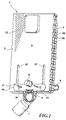
- the installation element shown in Fig. 1 has one Shaped body 1 made of a sound-absorbing material, preferred foamed polystyrene, on.
- the molded body 1 consists of a Front shell 2 and a rear shell 3.
- a cistern 4 In the molded body 1 is a cistern 4 with a drain pipe (as in Fig. 16) installed.
- the lower end of the drain pipe 5 looks at the front 6 of the molded body 1 (Fig. 1).
- the installation element from Fig. 1 for sanitary installations is attached to a wall via a mounting rail 9 and clamped over an end plate 10.
- the front shell 2 has a substantially flat front 6, which are provided with a surface profile 12 is as shown in detail in Fig. 2. Apart from this surface profiling 12 is the front 6 essentially, as can be seen from the side view just. There is also a front shell 2 Access opening 13 for later engagement of actuators available in connection with the cistern 4. At the bottom At the end of the front shell 2 there is an exit opening 14 for the drain pipe 5 of the cistern 4. In addition extend at the lower end two at a distance from each other arranged receiving openings 15 in the described later Way of fastening the installation element to serve.
- a relatively large-volume recording space 16 is provided for receiving the cistern 4.
- a stable rib structure 17 with several cavities 18.
- the rib structure 17 extends approximately half the height of the front shell 2 and essentially serves to stabilize the lower Range, the cavities 18 further reinforce the sound insulation.
- bowl-shaped Ribs 19 are provided which, when the cistern 4 is installed support the drain pipe 5. Between these bowl-shaped Ribs 20 are also arranged.
- FIG. 4 shows that at the lower edge of the front shell 2 a receiving pocket 23rd is arranged, which is used to arrange further components.
- the rear shell 3 is shaped so that it fits snugly on the Front shell 2 can be attached or vice versa.
- Receiving space 26 is provided for receiving the cistern 4.
- On the sides of the receiving space 26 are support ribs 27, which, as can be seen in Fig. 14, on the outer contour of the Cistern 4 are adapted so that this on the ribs 27th lies on. Furthermore, it is located in the upper area of the Recording space 26 a port opening open from the rear 28, accessible from the rear 29 of the rear shell 3 is. About the port opening 28 takes place later Water supply to the cistern 4.
- the lower area of the rear shell 3 is similar to the front shell 2 shows a rib structure 30 with cavities 31 for elevation stability with good sound insulation properties. In the middle of this area there is a perfect fit to the front shell 2 ribs 32 and cavities 33 to enclose and soundproofing the drain pipe 5 of the cistern 4th
- the rear 29 of the rear shell 3 is in the lower area formed with a shoulder 36, which is used to hold the fastening rail 9 serves so that the back 29 is flush with the wall can concern.
- the side surfaces 37 of the rear shell 3 are also with provided with a surface profile 38, in particular can be seen with reference to FIG. 9.
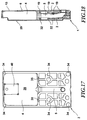
- FIG. 17 and 18 is the installation of the cistern 4 in to recognize the molded body 1. This is on the support ribs 27 of the receiving space 26 of the rear shell 3. As well there is the drain pipe 5 on the fins 32.
- FIG. 18 illustrates like after the front cover 2 of the cistern 4 and the drain pipe 5 except for the necessary feed and Departures completely enclosed and clearly in the Location is fixed.
- the rib structures 17 of the front shell 2 and 33 of the rear shell 3 abut each other and the edges the shells 2 and 3 are equipped so that they are soundproof interlock.
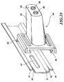
- the attachment is carried out by means of the fastening rail 9, which is essentially a U-shaped cross section with outward pointing end webs 41 on the U-legs 42.
- the mounting rail 9 is on the openings 43 on the Wall mountable.
- a fastening bolt can be pushed onto the fastening rail 9 44, which has a tapered plug-in section 45 and a C-shaped mounting plate at its thicker end 46 has.
- the mounting plate 46 is so in cross section designed that they laterally on the mounting rail 9th can be pushed on, but not removed perpendicular to the wall can be.
- the contour of the plug section 45 is to the inner contour of the Adjusted openings 15 in the molded body 1.
- the length of the Plug section 45, starting from the directly adjacent to this Surface 47 of the mounting plate 46 up to the end face 48 of the plug section 45 is slightly less than that Total thickness of the molded body 1 in the area of the receiving openings 15.
- the mounting plate 46 can be made in one piece with the Plug section 45 may be formed or manufactured separately and be attached to it.
- two threaded holes 49 and 50 are arranged in the end face 48 of the Plug section 45. On the one hand, these are used to screw in the screws shown in Fig. 1 shown threaded rods 11 and the other for screwing the fastening screws 51 (see also Fig. 1) for Attach the end plate 10 to the front 6 of the Shaped body 1.
- the end plate 10 is shown in Fig. 20.
- the end plate 10 has a collar 52 which fits into a groove 53 engages on the front shell 2 (see Fig. 2) with a precise fit.
- the Holes 54 and 55 each serve to receive either Threaded rod 11 or the fastening screw 51, for which this are each provided with a countersink.
- 21 is now shown as a drain pipe 7 (see also FIG. 1) also on the molded body 1 soundproofing can be attached.
- the front shell points to this 2 on its front 6 the receiving pocket 23 in which a correspondingly shaped section of the pipe clamp 8 fits exactly and is flush with the front 6 of the front shell 2 completes.
- a screw 56 can Fastening can be used.
- the pipe clamp 8 is off Plastic made so that a soundproof suspension the drain pipe 7 is given. 21 is can also be seen very well, like the collar 52 of the end plate 10 engages in the groove 53 in the front shell 2.
- the Pipe clamp 8 is made in two parts and its lower part 8b can be attached to the upper part 8a, one area the drain pipe 7 is positively gripped. By this attachment will also be the sound absorbing suspension of the Drain pipe 7 brought about on the molded body 1.
- a mechanic will prefer the installation after the meter has been torn make.
- 1 markings can additionally be made on the molded body attached to facilitate alignment.
- Installation begins with the fastening of the fastening rail on the wall after the appropriate element positions and rail positions have been marked.
- the molded body 1 is large and is provided with a surface profile 12, 25 and 38, can be integrated into the wall structure. That means, that immediately plastering with mortar of the molding 1 and a subsequent tiling or bricking can take place.
- the rib structures 17 and 30 confer the installation element has sufficient strength, so that the attachment by means of the fastening bolts 44 in is generally sufficient.
- the upper area of the molded body 1 has sufficient strength because of this is also stabilized by the cistern 4. However, there is the possibility of also the upper section of the molded body 1 to fix on the wall again. Are preferred here soundproofing attachment means used.
- the toilet body After tiling, the toilet body can be attached will.
- Front 6 of the front shell 2 grooves 47 introduced can be that have a certain length and to the ground of the molded body 1 are open. On the back of the back shell 3 similar grooves can be made.
- These benefits 57 can be used to push on the molded body 1 at wallless Serve lineup.
- a substructure be provided, on which the molded body 1 is attached.
- the fixation can in turn take place via the end plate 10, that the corresponding element inserted into the groove 57 fixed in this.
- the installation element according to the invention is in the assembly and of great advantage in manufacturing. At the same time adequate soundproofing is provided as all sound-generating parts arranged soundproofed in this or are held on this.
- the separate preforming of Half shells 2 is a crucial advance on this Area and results in significant cost savings.
- the installation element is not on the Use case of a toilet plumbing installation described here should be limited.
- the installation element can also be used for e.g. Bidet, urinal, shower, sink, Bathtubs etc. Sanitary installations are used.
- the self-supporting attachment can also be designed in a variety of ways be. Because of the large number of possible combinations regarding material composition, density, Layer thicknesses and shapes in the field of plastics processing can the installation element the most different Properties are conferred.
Landscapes
- Life Sciences & Earth Sciences (AREA)
- Engineering & Computer Science (AREA)
- Hydrology & Water Resources (AREA)
- Public Health (AREA)
- Water Supply & Treatment (AREA)
- Health & Medical Sciences (AREA)
- Sanitary Device For Flush Toilet (AREA)
- Pipe Accessories (AREA)
- Building Environments (AREA)
- Bidet-Like Cleaning Device And Other Flush Toilet Accessories (AREA)
- Paper (AREA)
- Diaphragms For Electromechanical Transducers (AREA)
- Mattresses And Other Support Structures For Chairs And Beds (AREA)
Applications Claiming Priority (2)
| Application Number | Priority Date | Filing Date | Title |
|---|---|---|---|
| DE19635759 | 1996-09-03 | ||
| DE19635759A DE19635759A1 (de) | 1996-09-03 | 1996-09-03 | Installationselement für Sanitärinstallationen |
Publications (3)
| Publication Number | Publication Date |
|---|---|
| EP0826837A1 true EP0826837A1 (fr) | 1998-03-04 |
| EP0826837B1 EP0826837B1 (fr) | 2001-08-29 |
| EP0826837B2 EP0826837B2 (fr) | 2008-10-22 |
Family
ID=7804523
Family Applications (1)
| Application Number | Title | Priority Date | Filing Date |
|---|---|---|---|
| EP97112651A Expired - Lifetime EP0826837B2 (fr) | 1996-09-03 | 1997-07-23 | Elément pour installation sanitaire |
Country Status (5)
| Country | Link |
|---|---|
| EP (1) | EP0826837B2 (fr) |
| AT (1) | ATE204939T1 (fr) |
| DE (2) | DE19635759A1 (fr) |
| ES (1) | ES2163072T5 (fr) |
| PT (1) | PT826837E (fr) |
Cited By (6)
| Publication number | Priority date | Publication date | Assignee | Title |
|---|---|---|---|---|
| DE20211758U1 (de) * | 2002-07-31 | 2003-12-11 | Franz Viegener Ii Gmbh & Co. Kg | Installationseinheit |
| EP2740849A4 (fr) * | 2011-09-21 | 2015-03-11 | Fominaya Sa | Châssis encastrable destiné à fixer des éléments sanitaires et procédé de fabrication correspondant |
| NO20150209A1 (en) * | 2015-02-12 | 2016-08-15 | Arvid Hanstad As | Concealed toilet cistern assembly |
| EP3067477A1 (fr) * | 2015-03-11 | 2016-09-14 | Raccords et Plastiques Nicoll | Dispositif de fixation pour bâti support, ensemble de fixation comprenant un tel dispositif et procédé de fixation sur un bâti support |
| FR3033581A1 (fr) * | 2015-03-11 | 2016-09-16 | Nicoll Raccords Plastiques | Bati support pour installation sanitaire du type encastree et procede de montage pour installation sanitaire du type encastree |
| US20240011272A1 (en) * | 2020-11-26 | 2024-01-11 | Reuven Zion | Wall for tiling |
Citations (4)
| Publication number | Priority date | Publication date | Assignee | Title |
|---|---|---|---|---|
| DE3736679A1 (de) * | 1987-10-29 | 1989-05-11 | Anton Nachbar | Verbindungsanordnung zwischen einem sanitaergegenstand und wasserleitungsrohren, insbesondere zur installation an leichtbauwaenden |
| DE8907973U1 (de) * | 1989-06-29 | 1989-09-14 | Sanbloc GmbH, 8120 Weilheim | Installationsbaustein oder -block |
| EP0480296A1 (fr) * | 1990-10-11 | 1992-04-15 | MERO-Werke Dr.-Ing. Max Mengeringhausen GmbH & Co. | Bloc d'installation sanitaire |
| DE9116144U1 (de) * | 1991-02-27 | 1992-05-07 | Mero-Werke Dr.-Ing. Max Mengeringhausen GmbH & Co, 8700 Würzburg | Installationsblock |
Family Cites Families (6)
| Publication number | Priority date | Publication date | Assignee | Title |
|---|---|---|---|---|
| DE1276561B (de) * | 1964-01-10 | 1968-08-29 | Hansa Metallwerke Ag | Installationswand |
| DE2637719C3 (de) * | 1976-08-21 | 1979-02-22 | Hansa Metallwerke Ag, 7000 Stuttgart | Unterputz-Armatur |
| CH649146A5 (en) * | 1980-07-01 | 1985-04-30 | Similor Sa | Connection fitting between a sanitary unit and a water line |
| DE3445474A1 (de) * | 1984-12-13 | 1986-06-19 | SCHWAB Sanitär-Plastic GmbH, 7417 Pfullingen | Sanitaerbaustein |
| DE3907931C2 (de) * | 1989-03-13 | 1999-03-11 | Hansa Metallwerke Ag | Sanitäre Unterputzarmatur |
| EP0646678B1 (fr) * | 1993-09-30 | 1999-02-10 | Emil Grumbach | Elément de construction d'installation préfabriquée |
-
1996
- 1996-09-03 DE DE19635759A patent/DE19635759A1/de not_active Withdrawn
-
1997
- 1997-07-23 DE DE59704427T patent/DE59704427D1/de not_active Expired - Lifetime
- 1997-07-23 PT PT97112651T patent/PT826837E/pt unknown
- 1997-07-23 ES ES97112651T patent/ES2163072T5/es not_active Expired - Lifetime
- 1997-07-23 EP EP97112651A patent/EP0826837B2/fr not_active Expired - Lifetime
- 1997-07-23 AT AT97112651T patent/ATE204939T1/de not_active IP Right Cessation
Patent Citations (4)
| Publication number | Priority date | Publication date | Assignee | Title |
|---|---|---|---|---|
| DE3736679A1 (de) * | 1987-10-29 | 1989-05-11 | Anton Nachbar | Verbindungsanordnung zwischen einem sanitaergegenstand und wasserleitungsrohren, insbesondere zur installation an leichtbauwaenden |
| DE8907973U1 (de) * | 1989-06-29 | 1989-09-14 | Sanbloc GmbH, 8120 Weilheim | Installationsbaustein oder -block |
| EP0480296A1 (fr) * | 1990-10-11 | 1992-04-15 | MERO-Werke Dr.-Ing. Max Mengeringhausen GmbH & Co. | Bloc d'installation sanitaire |
| DE9116144U1 (de) * | 1991-02-27 | 1992-05-07 | Mero-Werke Dr.-Ing. Max Mengeringhausen GmbH & Co, 8700 Würzburg | Installationsblock |
Cited By (6)
| Publication number | Priority date | Publication date | Assignee | Title |
|---|---|---|---|---|
| DE20211758U1 (de) * | 2002-07-31 | 2003-12-11 | Franz Viegener Ii Gmbh & Co. Kg | Installationseinheit |
| EP2740849A4 (fr) * | 2011-09-21 | 2015-03-11 | Fominaya Sa | Châssis encastrable destiné à fixer des éléments sanitaires et procédé de fabrication correspondant |
| NO20150209A1 (en) * | 2015-02-12 | 2016-08-15 | Arvid Hanstad As | Concealed toilet cistern assembly |
| EP3067477A1 (fr) * | 2015-03-11 | 2016-09-14 | Raccords et Plastiques Nicoll | Dispositif de fixation pour bâti support, ensemble de fixation comprenant un tel dispositif et procédé de fixation sur un bâti support |
| FR3033581A1 (fr) * | 2015-03-11 | 2016-09-16 | Nicoll Raccords Plastiques | Bati support pour installation sanitaire du type encastree et procede de montage pour installation sanitaire du type encastree |
| US20240011272A1 (en) * | 2020-11-26 | 2024-01-11 | Reuven Zion | Wall for tiling |
Also Published As
| Publication number | Publication date |
|---|---|
| ES2163072T3 (es) | 2002-01-16 |
| DE19635759A1 (de) | 1998-03-05 |
| DE59704427D1 (de) | 2001-10-04 |
| ES2163072T5 (es) | 2009-04-01 |
| ATE204939T1 (de) | 2001-09-15 |
| EP0826837B1 (fr) | 2001-08-29 |
| EP0826837B2 (fr) | 2008-10-22 |
| PT826837E (pt) | 2002-01-30 |
Similar Documents
| Publication | Publication Date | Title |
|---|---|---|
| EP0853753B1 (fr) | Module de montage pour installation sanitaire et son procede de fabrication | |
| EP2101002B1 (fr) | Boîtier d'encastrement destiné à l'encastrement variable d'armatures sanitaires | |
| EP2821557A1 (fr) | Réservoir de chasse intégré doté d'un dispositif de protection contre les fuites | |
| EP2756137B1 (fr) | Caniveau d'évacuation pour une douche ras du sol | |
| EP0826837B1 (fr) | Elément pour installation sanitaire | |
| EP0731226B1 (fr) | Elément pour l'assemblage d'une installation sanitaire devant une paroi | |
| EP0495238B1 (fr) | Ensemble d'éléments de construction pour douches rondes | |
| DE3906758C2 (fr) | ||
| DE19948468C2 (de) | Aufsatz-Rollladenkasten | |
| DE29623724U1 (de) | Installationselement für Sanitärinstallationen | |
| DE29508686U1 (de) | Bausatz zum Erstellen von Umkleidekabinen, Trennwänden u.dgl. | |
| EP0790359B1 (fr) | Dispositif de fixation pour article sanitaire | |
| EP0166234A2 (fr) | Boîte de jonction pour installation de distribution d'eau | |
| EP0662546A2 (fr) | Bloc de construction, pour la fixation d'installations et/ou appareils sanitaires sur une paroi | |
| DE19844509A1 (de) | Vorwand-Element zur Sanitärinstallation | |
| EP0733750B1 (fr) | Moyens de raccordement pour un réservoir de chasse d'eau | |
| EP1803859A2 (fr) | Composant de paroi destiné à la fixation porteuse d'au moins un objet sanitaire et son procédé de fabrication | |
| DE202006006507U1 (de) | Anordnung für eine Scheibenbefestigung und/oder Raumabtrennung, insbesondere eine Duschabtrennung oder Dampfkabine | |
| DE29714609U1 (de) | Vorgefertigte Montagebox für den Heizungs- und Rohrleitungsbau sowie den Sanitärbereich | |
| DE19949278A1 (de) | Verfahren zur Herstellung der Außenwände eines Massivhauses und Verbundschalung | |
| DE8906225U1 (de) | Vorrichtung zum Abstützen und Verkleiden einer Badewanne od.dgl. | |
| EP0116012B1 (fr) | Socle-élément préfabriqué pour baignoires et cuvettes de douches | |
| DE10249002B4 (de) | Sanitärrauminstallation, insbesondere für öffentliche Gebäude und Bürogebäude | |
| DE202018101214U1 (de) | Vorrichtung zur Befestigung einer Sanitäreinrichtung an einer Wand sowie Sanitäreinrichtung mit einer solchen Vorrichtung | |
| DE3700878A1 (de) | Sanitaer-fertigblock |
Legal Events
| Date | Code | Title | Description |
|---|---|---|---|
| PUAI | Public reference made under article 153(3) epc to a published international application that has entered the european phase |
Free format text: ORIGINAL CODE: 0009012 |
|
| AK | Designated contracting states |
Kind code of ref document: A1 Designated state(s): AT BE CH DE DK ES FI FR GB GR IE IT LI NL PT SE |
|
| AX | Request for extension of the european patent |
Free format text: AL;LT;LV;RO;SI |
|
| 17P | Request for examination filed |
Effective date: 19980520 |
|
| AKX | Designation fees paid |
Free format text: AT BE CH DE DK ES FI FR GB GR IE IT LI NL PT SE |
|
| RBV | Designated contracting states (corrected) |
Designated state(s): AT BE CH DE DK ES FI FR GB GR IE IT LI NL PT SE |
|
| 17Q | First examination report despatched |
Effective date: 19990414 |
|
| GRAG | Despatch of communication of intention to grant |
Free format text: ORIGINAL CODE: EPIDOS AGRA |
|
| 17Q | First examination report despatched |
Effective date: 19990414 |
|
| GRAG | Despatch of communication of intention to grant |
Free format text: ORIGINAL CODE: EPIDOS AGRA |
|
| GRAG | Despatch of communication of intention to grant |
Free format text: ORIGINAL CODE: EPIDOS AGRA |
|
| GRAH | Despatch of communication of intention to grant a patent |
Free format text: ORIGINAL CODE: EPIDOS IGRA |
|
| GRAH | Despatch of communication of intention to grant a patent |
Free format text: ORIGINAL CODE: EPIDOS IGRA |
|
| GRAA | (expected) grant |
Free format text: ORIGINAL CODE: 0009210 |
|
| RAP1 | Party data changed (applicant data changed or rights of an application transferred) |
Owner name: DAL GMBH & CO. GMBH |
|
| RAP1 | Party data changed (applicant data changed or rights of an application transferred) |
Owner name: DAL GMBH & CO.KG |
|
| AK | Designated contracting states |
Kind code of ref document: B1 Designated state(s): AT BE CH DE DK ES FI FR GB GR IE IT LI NL PT SE |
|
| PG25 | Lapsed in a contracting state [announced via postgrant information from national office to epo] |
Ref country code: IE Free format text: LAPSE BECAUSE OF FAILURE TO SUBMIT A TRANSLATION OF THE DESCRIPTION OR TO PAY THE FEE WITHIN THE PRESCRIBED TIME-LIMIT Effective date: 20010829 Ref country code: FI Free format text: LAPSE BECAUSE OF FAILURE TO SUBMIT A TRANSLATION OF THE DESCRIPTION OR TO PAY THE FEE WITHIN THE PRESCRIBED TIME-LIMIT Effective date: 20010829 |
|
| REF | Corresponds to: |
Ref document number: 204939 Country of ref document: AT Date of ref document: 20010915 Kind code of ref document: T |
|
| REG | Reference to a national code |
Ref country code: CH Ref legal event code: NV Representative=s name: BOVARD AG PATENTANWAELTE Ref country code: CH Ref legal event code: EP |
|
| REG | Reference to a national code |
Ref country code: IE Ref legal event code: FG4D Free format text: GERMAN |
|
| REF | Corresponds to: |
Ref document number: 59704427 Country of ref document: DE Date of ref document: 20011004 |
|
| GBT | Gb: translation of ep patent filed (gb section 77(6)(a)/1977) |
Effective date: 20011030 |
|
| PG25 | Lapsed in a contracting state [announced via postgrant information from national office to epo] |
Ref country code: DK Free format text: LAPSE BECAUSE OF FAILURE TO SUBMIT A TRANSLATION OF THE DESCRIPTION OR TO PAY THE FEE WITHIN THE PRESCRIBED TIME-LIMIT Effective date: 20011129 |
|
| PG25 | Lapsed in a contracting state [announced via postgrant information from national office to epo] |
Ref country code: GR Free format text: LAPSE BECAUSE OF FAILURE TO SUBMIT A TRANSLATION OF THE DESCRIPTION OR TO PAY THE FEE WITHIN THE PRESCRIBED TIME-LIMIT Effective date: 20011130 |
|
| REG | Reference to a national code |
Ref country code: GB Ref legal event code: IF02 |
|
| ET | Fr: translation filed | ||
| REG | Reference to a national code |
Ref country code: ES Ref legal event code: FG2A Ref document number: 2163072 Country of ref document: ES Kind code of ref document: T3 |
|
| REG | Reference to a national code |
Ref country code: PT Ref legal event code: SC4A Free format text: AVAILABILITY OF NATIONAL TRANSLATION Effective date: 20011023 |
|
| REG | Reference to a national code |
Ref country code: IE Ref legal event code: FD4D |
|
| PLBI | Opposition filed |
Free format text: ORIGINAL CODE: 0009260 |
|
| 26 | Opposition filed |
Opponent name: CREVAN S.R.L. Effective date: 20020527 |
|
| PLAB | Opposition data, opponent's data or that of the opponent's representative modified |
Free format text: ORIGINAL CODE: 0009299OPPO |
|
| PLBF | Reply of patent proprietor to notice(s) of opposition |
Free format text: ORIGINAL CODE: EPIDOS OBSO |
|
| PLBQ | Unpublished change to opponent data |
Free format text: ORIGINAL CODE: EPIDOS OPPO |
|
| NLR1 | Nl: opposition has been filed with the epo |
Opponent name: CREVAN S.R.L. |
|
| R26 | Opposition filed (corrected) |
Opponent name: CREVAN S.R.L. Effective date: 20020527 |
|
| NLR1 | Nl: opposition has been filed with the epo |
Opponent name: CREVAN S.R.L. |
|
| PLBF | Reply of patent proprietor to notice(s) of opposition |
Free format text: ORIGINAL CODE: EPIDOS OBSO |
|
| PLBF | Reply of patent proprietor to notice(s) of opposition |
Free format text: ORIGINAL CODE: EPIDOS OBSO |
|
| PLBQ | Unpublished change to opponent data |
Free format text: ORIGINAL CODE: EPIDOS OPPO |
|
| PLAB | Opposition data, opponent's data or that of the opponent's representative modified |
Free format text: ORIGINAL CODE: 0009299OPPO |
|
| R26 | Opposition filed (corrected) |
Opponent name: CREVAN S.R.L. Effective date: 20020527 |
|
| NLR1 | Nl: opposition has been filed with the epo |
Opponent name: CREVAN S.R.L. |
|
| PLBQ | Unpublished change to opponent data |
Free format text: ORIGINAL CODE: EPIDOS OPPO |
|
| PLAB | Opposition data, opponent's data or that of the opponent's representative modified |
Free format text: ORIGINAL CODE: 0009299OPPO |
|
| R26 | Opposition filed (corrected) |
Opponent name: CREVAN S.R.L. Effective date: 20020527 |
|
| NLR1 | Nl: opposition has been filed with the epo |
Opponent name: CREVAN S.R.L. |
|
| PLAB | Opposition data, opponent's data or that of the opponent's representative modified |
Free format text: ORIGINAL CODE: 0009299OPPO |
|
| PLAQ | Examination of admissibility of opposition: information related to despatch of communication + time limit deleted |
Free format text: ORIGINAL CODE: EPIDOSDOPE2 |
|
| PLAR | Examination of admissibility of opposition: information related to receipt of reply deleted |
Free format text: ORIGINAL CODE: EPIDOSDOPE4 |
|
| PLBQ | Unpublished change to opponent data |
Free format text: ORIGINAL CODE: EPIDOS OPPO |
|
| RDAF | Communication despatched that patent is revoked |
Free format text: ORIGINAL CODE: EPIDOSNREV1 |
|
| R26 | Opposition filed (corrected) |
Opponent name: CREVAN S.R.L. Effective date: 20020527 |
|
| APBP | Date of receipt of notice of appeal recorded |
Free format text: ORIGINAL CODE: EPIDOSNNOA2O |
|
| APBM | Appeal reference recorded |
Free format text: ORIGINAL CODE: EPIDOSNREFNO |
|
| NLR1 | Nl: opposition has been filed with the epo |
Opponent name: CREVAN S.R.L. |
|
| APBQ | Date of receipt of statement of grounds of appeal recorded |
Free format text: ORIGINAL CODE: EPIDOSNNOA3O |
|
| APAH | Appeal reference modified |
Free format text: ORIGINAL CODE: EPIDOSCREFNO |
|
| PLAB | Opposition data, opponent's data or that of the opponent's representative modified |
Free format text: ORIGINAL CODE: 0009299OPPO |
|
| R26 | Opposition filed (corrected) |
Opponent name: CREVAN S.R.L. Effective date: 20020527 |
|
| APBU | Appeal procedure closed |
Free format text: ORIGINAL CODE: EPIDOSNNOA9O |
|
| NLR1 | Nl: opposition has been filed with the epo |
Opponent name: CREVAN S.R.L. |
|
| PLAB | Opposition data, opponent's data or that of the opponent's representative modified |
Free format text: ORIGINAL CODE: 0009299OPPO |
|
| R26 | Opposition filed (corrected) |
Opponent name: CREVAN S.R.L. Effective date: 20020527 |
|
| PUAH | Patent maintained in amended form |
Free format text: ORIGINAL CODE: 0009272 |
|
| STAA | Information on the status of an ep patent application or granted ep patent |
Free format text: STATUS: PATENT MAINTAINED AS AMENDED |
|
| 27A | Patent maintained in amended form |
Effective date: 20081022 |
|
| AK | Designated contracting states |
Kind code of ref document: B2 Designated state(s): AT BE CH DE DK ES FI FR GB GR IE IT LI NL PT SE |
|
| REG | Reference to a national code |
Ref country code: CH Ref legal event code: AEN Free format text: AUFRECHTERHALTUNG DES PATENTES IN GEAENDERTER FORM |
|
| NLR1 | Nl: opposition has been filed with the epo |
Opponent name: CREVAN S.R.L. |
|
| NLR2 | Nl: decision of opposition |
Effective date: 20081022 |
|
| REG | Reference to a national code |
Ref country code: SE Ref legal event code: RPEO |
|
| NLR3 | Nl: receipt of modified translations in the netherlands language after an opposition procedure | ||
| REG | Reference to a national code |
Ref country code: ES Ref legal event code: DC2A Date of ref document: 20090113 Kind code of ref document: T5 |
|
| PGFP | Annual fee paid to national office [announced via postgrant information from national office to epo] |
Ref country code: NL Payment date: 20100714 Year of fee payment: 14 Ref country code: CH Payment date: 20100726 Year of fee payment: 14 |
|
| PGFP | Annual fee paid to national office [announced via postgrant information from national office to epo] |
Ref country code: SE Payment date: 20100715 Year of fee payment: 14 Ref country code: IT Payment date: 20100727 Year of fee payment: 14 Ref country code: FR Payment date: 20100805 Year of fee payment: 14 Ref country code: AT Payment date: 20100714 Year of fee payment: 14 |
|
| PGFP | Annual fee paid to national office [announced via postgrant information from national office to epo] |
Ref country code: GB Payment date: 20100722 Year of fee payment: 14 |
|
| PGFP | Annual fee paid to national office [announced via postgrant information from national office to epo] |
Ref country code: PT Payment date: 20100716 Year of fee payment: 14 |
|
| PGFP | Annual fee paid to national office [announced via postgrant information from national office to epo] |
Ref country code: BE Payment date: 20100715 Year of fee payment: 14 |
|
| REG | Reference to a national code |
Ref country code: CH Ref legal event code: PFA Owner name: DAL GMBH & CO.KG Free format text: DAL GMBH & CO.KG#ZUR PORTA 8-12#32457 PORTA WESTFALICA (DE) -TRANSFER TO- DAL GMBH & CO.KG#ZUR PORTA 8-12#32457 PORTA WESTFALICA (DE) |
|
| REG | Reference to a national code |
Ref country code: PT Ref legal event code: MM4A Free format text: LAPSE DUE TO NON-PAYMENT OF FEES Effective date: 20120123 |
|
| BERE | Be: lapsed |
Owner name: *DAL G.M.B.H. & CO. K.G. Effective date: 20110731 |
|
| REG | Reference to a national code |
Ref country code: NL Ref legal event code: V1 Effective date: 20120201 |
|
| REG | Reference to a national code |
Ref country code: CH Ref legal event code: PL |
|
| REG | Reference to a national code |
Ref country code: SE Ref legal event code: EUG |
|
| GBPC | Gb: european patent ceased through non-payment of renewal fee |
Effective date: 20110723 |
|
| REG | Reference to a national code |
Ref country code: AT Ref legal event code: MM01 Ref document number: 204939 Country of ref document: AT Kind code of ref document: T Effective date: 20110723 |
|
| REG | Reference to a national code |
Ref country code: FR Ref legal event code: ST Effective date: 20120330 |
|
| PG25 | Lapsed in a contracting state [announced via postgrant information from national office to epo] |
Ref country code: CH Free format text: LAPSE BECAUSE OF NON-PAYMENT OF DUE FEES Effective date: 20110731 Ref country code: LI Free format text: LAPSE BECAUSE OF NON-PAYMENT OF DUE FEES Effective date: 20110731 Ref country code: BE Free format text: LAPSE BECAUSE OF NON-PAYMENT OF DUE FEES Effective date: 20110731 Ref country code: FR Free format text: LAPSE BECAUSE OF NON-PAYMENT OF DUE FEES Effective date: 20110801 |
|
| PG25 | Lapsed in a contracting state [announced via postgrant information from national office to epo] |
Ref country code: PT Free format text: LAPSE BECAUSE OF NON-PAYMENT OF DUE FEES Effective date: 20120123 Ref country code: IT Free format text: LAPSE BECAUSE OF NON-PAYMENT OF DUE FEES Effective date: 20110723 Ref country code: NL Free format text: LAPSE BECAUSE OF NON-PAYMENT OF DUE FEES Effective date: 20120201 |
|
| PG25 | Lapsed in a contracting state [announced via postgrant information from national office to epo] |
Ref country code: GB Free format text: LAPSE BECAUSE OF NON-PAYMENT OF DUE FEES Effective date: 20110723 |
|
| PG25 | Lapsed in a contracting state [announced via postgrant information from national office to epo] |
Ref country code: AT Free format text: LAPSE BECAUSE OF NON-PAYMENT OF DUE FEES Effective date: 20110723 |
|
| PG25 | Lapsed in a contracting state [announced via postgrant information from national office to epo] |
Ref country code: SE Free format text: LAPSE BECAUSE OF NON-PAYMENT OF DUE FEES Effective date: 20110724 |
|
| PGFP | Annual fee paid to national office [announced via postgrant information from national office to epo] |
Ref country code: ES Payment date: 20150728 Year of fee payment: 19 |
|
| PGFP | Annual fee paid to national office [announced via postgrant information from national office to epo] |
Ref country code: DE Payment date: 20160722 Year of fee payment: 20 |
|
| REG | Reference to a national code |
Ref country code: DE Ref legal event code: R071 Ref document number: 59704427 Country of ref document: DE |
|
| REG | Reference to a national code |
Ref country code: ES Ref legal event code: FD2A Effective date: 20180507 |
|
| PG25 | Lapsed in a contracting state [announced via postgrant information from national office to epo] |
Ref country code: ES Free format text: LAPSE BECAUSE OF NON-PAYMENT OF DUE FEES Effective date: 20160724 |