EP0826837B1 - Elément pour installation sanitaire - Google Patents
Elément pour installation sanitaire Download PDFInfo
- Publication number
- EP0826837B1 EP0826837B1 EP97112651A EP97112651A EP0826837B1 EP 0826837 B1 EP0826837 B1 EP 0826837B1 EP 97112651 A EP97112651 A EP 97112651A EP 97112651 A EP97112651 A EP 97112651A EP 0826837 B1 EP0826837 B1 EP 0826837B1
- Authority
- EP
- European Patent Office
- Prior art keywords
- element according
- installation element
- moulded body
- moulded
- fixing means
- Prior art date
- Legal status (The legal status is an assumption and is not a legal conclusion. Google has not performed a legal analysis and makes no representation as to the accuracy of the status listed.)
- Expired - Lifetime
Links
- 238000009434 installation Methods 0.000 title claims description 66
- XLYOFNOQVPJJNP-UHFFFAOYSA-N water Substances O XLYOFNOQVPJJNP-UHFFFAOYSA-N 0.000 claims abstract description 5
- 239000011810 insulating material Substances 0.000 claims abstract description 3
- 238000004079 fireproofing Methods 0.000 claims abstract 2
- 238000009413 insulation Methods 0.000 claims description 8
- 239000000463 material Substances 0.000 claims description 5
- 239000004033 plastic Substances 0.000 claims description 5
- 229920003023 plastic Polymers 0.000 claims description 5
- 239000004793 Polystyrene Substances 0.000 claims description 3
- 229920002223 polystyrene Polymers 0.000 claims description 3
- 238000003780 insertion Methods 0.000 claims description 2
- 230000037431 insertion Effects 0.000 claims description 2
- 238000011010 flushing procedure Methods 0.000 claims 9
- 239000002699 waste material Substances 0.000 claims 2
- 230000004308 accommodation Effects 0.000 claims 1
- 230000002459 sustained effect Effects 0.000 claims 1
- 238000009428 plumbing Methods 0.000 abstract 2
- 238000010521 absorption reaction Methods 0.000 abstract 1
- 238000004519 manufacturing process Methods 0.000 description 7
- 238000000465 moulding Methods 0.000 description 5
- 239000011358 absorbing material Substances 0.000 description 4
- 230000008901 benefit Effects 0.000 description 3
- 239000002184 metal Substances 0.000 description 3
- 238000000034 method Methods 0.000 description 3
- 241000408710 Hansa Species 0.000 description 2
- 238000005253 cladding Methods 0.000 description 2
- 150000001875 compounds Chemical class 0.000 description 2
- 238000013461 design Methods 0.000 description 2
- 230000000694 effects Effects 0.000 description 2
- 238000005516 engineering process Methods 0.000 description 2
- 239000006260 foam Substances 0.000 description 2
- 239000004570 mortar (masonry) Substances 0.000 description 2
- 230000008569 process Effects 0.000 description 2
- 239000000725 suspension Substances 0.000 description 2
- 238000012549 training Methods 0.000 description 2
- 229920006328 Styrofoam Polymers 0.000 description 1
- 239000000853 adhesive Substances 0.000 description 1
- 230000001070 adhesive effect Effects 0.000 description 1
- 239000002390 adhesive tape Substances 0.000 description 1
- 239000011248 coating agent Substances 0.000 description 1
- 238000000576 coating method Methods 0.000 description 1
- 238000009833 condensation Methods 0.000 description 1
- 230000005494 condensation Effects 0.000 description 1
- 238000010276 construction Methods 0.000 description 1
- -1 density Substances 0.000 description 1
- 238000009826 distribution Methods 0.000 description 1
- 238000005538 encapsulation Methods 0.000 description 1
- 229920006248 expandable polystyrene Polymers 0.000 description 1
- 230000002349 favourable effect Effects 0.000 description 1
- 230000009969 flowable effect Effects 0.000 description 1
- 238000005187 foaming Methods 0.000 description 1
- 230000007246 mechanism Effects 0.000 description 1
- 239000002557 mineral fiber Substances 0.000 description 1
- 239000000203 mixture Substances 0.000 description 1
- 238000004806 packaging method and process Methods 0.000 description 1
- 239000011505 plaster Substances 0.000 description 1
- 238000012545 processing Methods 0.000 description 1
- 230000003716 rejuvenation Effects 0.000 description 1
- 230000008439 repair process Effects 0.000 description 1
- 239000007779 soft material Substances 0.000 description 1
- 239000008261 styrofoam Substances 0.000 description 1
- 230000007704 transition Effects 0.000 description 1
Images


Classifications
-
- E—FIXED CONSTRUCTIONS
- E03—WATER SUPPLY; SEWERAGE
- E03D—WATER-CLOSETS OR URINALS WITH FLUSHING DEVICES; FLUSHING VALVES THEREFOR
- E03D11/00—Other component parts of water-closets, e.g. noise-reducing means in the flushing system, flushing pipes mounted in the bowl, seals for the bowl outlet, devices preventing overflow of the bowl contents; devices forming a water seal in the bowl after flushing, devices eliminating obstructions in the bowl outlet or preventing backflow of water and excrements from the waterpipe
- E03D11/13—Parts or details of bowls; Special adaptations of pipe joints or couplings for use with bowls, e.g. provisions in bowl construction preventing backflow of waste-water from the bowl in the flushing pipe or cistern, provisions for a secondary flushing, for noise-reducing
- E03D11/14—Means for connecting the bowl to the wall, e.g. to a wall outlet
- E03D11/143—Mounting frames for toilets and urinals
- E03D11/146—Mounting frames for toilets and urinals with incorporated cistern
Definitions
- the invention relates to an installation element for sanitary installations, with an insulating material Shaped body in which at least one cistern with a drain pipe is arranged.
- the invention further relates to a molded body for such an installation element.
- Such an installation module is from the German utility model DE-8907973 known.
- this device are the necessary for the supply and disposal of a sanitary apparatus Lines and components as well as those for attaching the Sanitary equipment necessary fasteners in a foamed Shaped body stored.
- Front and rear walls are essentially the whole Fire protection layer spread out in the block area. This layer becomes during the manufacturing process of the molded body firmly connected to the molding compound, so that it Becomes part of the molded body.
- the lines and components are correspondingly used in the foaming with the molding compound supported against buoyancy.
- one PUR molded body comprises, in the inner parts, in particular a Cistern, are molded directly. That means the inner parts are encapsulated by the plastic.
- cladding blocks that provide a smooth, flowable surface on the front, however open at the back and inside are not molded onto the sanitary elements.
- the cladding elements have inner contour sections on, into which pipes can be inserted.
- a catalog sheet from the Schell company with the print reference 1/95 shows on page 2.3 a urinal flush valve flush valve DN 15 VERONA. This obviously includes a two-part polystyrene coating. However, the catalog sheet does not indicates whether the styrofoam casing is only used as transport packaging serves or should be plastered into the wall.
- connection boxes are mainly for wall installation provided and are, as far as the prospectus recognizes leaves, in one piece, partly with directly molded pipe pieces, designed.
- a Hansa flush-mounted universal installation body is known.
- This Installation body comprises two block elements, the front one Block element only when plastering to protect the underlying one Elements apply and then removed becomes.
- a similar installation body is from DE 3907931 C2 known.
- DE 30 35 935 Al deals with a connecting piece between a sanitary device and a water pipe.
- This Connector is in a cuboid of at least two one inside the other nestable parts arranged which the connector at least partially surrounded positively.
- the Parts consist of synthetic hard foam and are included an adhesive tape or a wire or a string held together.
- the assembly piece formed from the two elements is housed in a wall slot and then plastered. Alignment aids for plastering are also included in this Documentation described.
- an installation device is known from EP 0480296-A1 known, in which all sound generating installation components built into a sound-absorbing mineral fiber bed are.
- a metal frame is used to hold the components, which delimits the assembly room.
- the installation components are over soundproofed elements with the metal frame connected.
- a disadvantage with some of these devices is that relatively complex manufacture of the installation blocks because the sanitary elements before filling in the cavities sound-absorbing material must be fixed. Furthermore it must be ensured that the sound-absorbing material is introduced in such a way that it also covers almost all cavities achieved and essentially complete encapsulation of the sound-generating installation components.
- the present invention accordingly proposes the molded body to build from several individual parts, which are separate from the flush-mounted cistern to be installed with drain pipe.
- the inner contour of the shell elements is simple Way so tunable that the cistern with drain pipe only inserted in the appropriate place and by adding a other shell element is fixed. This also allows a complete enclosure of the cistern with a drain pipe to reach. Only the desired entrances and exits can accessible through corresponding openings in the molded body his.
- the invention also offers the advantage that the Inner contour of the shell elements for the installation of various Cisterns with a drain pipe can be molded so that there is a flexible modular system. Possibly larger distances would have to be bridged by additional insert elements become. Due to the shell construction, an additional Condensation water insulation, as has been the case up to now Technology is common, omitted.
- the entire cistern can be excellently shaped soundproof without causing major problems with the Manufacture of the installation module in contrast to the stand of technology. For example, fixing the cistern against buoyancy, as partly in the prior art, not be provided.
- the molded body is at a distance from the soundproofing Cistern with drain pipe intake openings. Furthermore fasteners are provided for insertion into the Receiving openings, especially for wall mounting, are used. Such training leaves a very simple arrangement of the installation element. The fasteners will be attached to the designated place and the molded body postponed. The molded body thus takes over the supporting or Support and arrangement function for the cistern with drain pipe. Other fasteners, which may be sound decoupled need not be provided. Because the receiving openings are formed by sound-absorbing material automatically a sound-insulating attachment of the installation element brought about.
- An embodiment proposes that at least a part or area of the cistern with drain pipe, especially water-storing and water-carrying parts or areas formed by the shell elements themselves are. As a result, it is largely possible to insert sanitary elements to be dispensed with because the cistern with drain pipe are formed by the inner contour of the molded body itself.
- the shell elements are frictionally engaged interlocking plug and socket elements with each other, especially waterproof, connected.
- This simple connection method can be realized very easily in terms of shape and ensures a snug fit together.
- the Plug and socket elements can also be designed in this way be that they are also insoluble and / or watertight connectable are.
- the molded body can be attached to at least two different ones Areas with different densities or insulation properties. Through the transition a buffer effect is achieved for different densities, which also improves the insulation properties.
- the Arrangement of areas of different densities can be done so that a stable support structure for the cistern with drain pipe in the molded body and all other areas filled with low density material are. As a result, the soundproofing effect of Shaped body optimized.
- the molded body can preferably be constructed in multiple layers.
- the individual layers can differ due to special Requirements. For example, a fire protection layer be provided.
- the layers or regions can advantageously be different Properties such as Density, strength, Have soundproofing or fire protection.
- At least the area around the receiving openings can preferably be of the molded body be sufficiently stable to a to provide self-supporting moldings without additional Fasteners for the cistern with a drain pipe are necessary.
- the receiving openings from the Back to the front of the molded body through the corresponding Shell elements extend through and the fasteners on its front side, accessible from the front Fastening devices, in particular at least one Have a tapped hole due to the external loads essentially from the fasteners are recordable.
- the fastener can be used by suitable Fastening devices in relation to the molded body can be locked or there is the possibility of additional attachments to attach to the fasteners that none Exercise loads on the molded body, as this on the molded body be directed past.
- a toilet body be screwed to the fasteners.
- the order the fasteners and the number of fasteners then depends on the type of to be attached Additional components. Fastening devices of the different arrangement and with different distances be provided so that entire series of add-on elements are connectable with the fasteners.
- a very good fixation of the molded body on the fastening bolt can be achieved in that the receiving openings from the back to the front of the molded body taper and fastening bolts as fasteners are provided, which are adapted accordingly in the outer contour are. Since the receiving openings are divided by at least two Shell elements extend through them additionally centered. This configuration also offers an easier installation because the fastening bolts always sit with a slight adhesive fit in the receiving openings, and moreover, no reverse installation of the molded body on fastening bolts is possible.
- the fastening means can advantageously have a stop surface for contact with a rear area of the molded body have, and an end plate for connecting be provided with the end face of the fastening means, that comes into contact with the front of the molded body, so that this between the stop surfaces on the fasteners and the end plate is clamped.
- the end plate ensures a large-scale contact with the molded body and for a good force distribution of the clamping force over the pressure surface. As a result, even a molded body can be made from relative attach soft material very well.
- the end plate can also be used to arrange additional components become. Several end plates can also be used.
- a fastening rail can be provided and the fastening means can guide devices for Sliding on or plugging onto the mounting rail exhibit. A hold in the direction of the load on the Mounting rail is also realized. Through this Measure will be the assembly of the installation module again facilitated. By sliding the fasteners on a rail these can be in different Intervals are attached as is for different Application is required. Beyond that too a row arrangement on a longer mounting rail possible. It is not yet with such a configuration once necessary to fasten the fastener from the molded body loosen to move it sideways on the mounting rail. Furthermore there is a push on, push on and / or screwing during assembly even without a rail possible.
- locking devices can be used for locking the fastening means provided on the fastening rail his. These are preferably integrated in the element.
- the molded body is made of foamed Manufacture plastic, especially polystyrene.
- rib elements are arranged in the interior of the molded body, which essentially fit precisely in areas on the sanitary elements and fix them. So that is the interface minimized between the sanitary elements and the molded body. They also serve between the individual rib elements cavities formed within the molded body additionally for sound insulation.
- a particularly favorable embodiment is a molded body ready from a box consisting of two half-shells.
- the division level of the two half-shells can parallel to the front and back of the molded body to run. This also makes it very easy to form a tight joint of the two half-shells.
- Molded pockets to hold and / or attach additional ones Sanitary elements and / or fastening or installation devices be provided.
- the components can e.g. precisely inserted into these shaped pockets and e.g. about the Cover plate can be locked using the fastening bolts.
- such shaped pockets can serve the push the entire molded body onto a support frame and to hold it like this. This means e.g. a lineup free possible in the room using a base frame.
- a pipe clamp, a drain pipe and a Shaped pocket for attaching the pipe clamp may be provided, wherein the drain pipe is soundproofed.
- the pipe clamp is at least partially in a shaped pocket on Shaped body inserted and held there, if necessary through the end plate. This automatically results in soundproofing Attachment of the drain pipe, so that none additional soundproof attachment provided for this have to be.
- the gradual bracing for adjustment enable in the pre-assembled state.
- These ledges serve to facilitate assembly and are after alignment deformed or destroyed.
- a fastener (or several) for attachment to the upper edge area of the molded body and be provided for wall connection.
- a molded body for a Installation element is characterized in that it consists of at least two Shell elements exist that essentially fit together to enclose a cistern accordingly Drain pipe can be added, with receiving openings at a distance the receiving contours for the cistern with drain pipe provided are. Moldings previously used could be used for repair purposes can no longer be separated from the sanitary elements, without causing the molded body to be destroyed has been. The new molded body is easier to manufacture open again if necessary and is more flexible in the design, for example during its manufacture no sanitary elements already inserted in the way are.
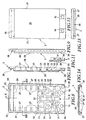
- the installation element shown in Fig. 1 has one Shaped body 1 made of a sound-absorbing material, preferred foamed polystyrene, on.
- the molded body 1 consists of a Front shell 2 and a rear shell 3.
- a cistern 4 In the molded body 1 is a cistern 4 with a drain pipe (as in Fig. 16) installed.
- the lower end of the drain pipe 5 looks at the front 6 of the molded body 1 (Fig. 1).
- the installation element from Fig. 1 for sanitary installations is attached to a wall via a mounting rail 9 and clamped over an end plate 10.
- the front shell 2 has a substantially flat front 6, which are provided with a surface profile 12 is as shown in detail in Fig. 2. Apart from this surface profiling 12 is the front 6 essentially, as can be seen from the side view just. There is also a front shell 2 Access opening 13 for later engagement of actuators available in connection with the cistern 4. At the bottom At the end of the front shell 2 there is an exit opening 14 for the drain pipe 5 of the cistern 4. In addition extend at the lower end two at a distance from each other arranged receiving openings 15 in the described later Way of fastening the installation element serve.
- a relatively large-volume recording space 16 is provided for receiving the cistern 4.
- a stable rib structure 17 with several cavities 18.
- the rib structure 17 extends approximately half the height of the front shell 2 and essentially serves to stabilize the lower Range, the cavities 18 further reinforce the sound insulation.
- bowl-shaped Ribs 19 are provided which, when the cistern 4 is installed support the drain pipe 5. Between these bowl-shaped Ribs 20 are also arranged.
- FIG. 4 shows that at the lower edge of the front shell 2 a receiving pocket 23rd is arranged, which is used to arrange further components.
- the rear shell 3 is shaped so that it fits snugly on the Front shell 2 can be attached or vice versa.
- Receiving space 26 is provided for receiving the cistern 4.
- On the sides of the receiving space 26 are support ribs 27, which, as can be seen in Fig. 14, on the outer contour of the Cistern 4 are adapted so that this on the ribs 27th lies on. Furthermore, it is located in the upper area of the Recording space 26 a port opening open from the rear 28, accessible from the rear 29 of the rear shell 3 is. About the port opening 28 takes place later Water supply to the cistern 4.
- the lower area of the rear shell 3 is similar to the front shell 2 shows a rib structure 30 with cavities 31 for elevation stability with good sound insulation properties. In the middle of this area there is a perfect fit to the front shell 2 ribs 32 and cavities 33 to enclose and soundproofing the drain pipe 5 of the cistern 4th
- the rear 29 of the rear shell 3 is in the lower area formed with a shoulder 36, which is used to hold the fastening rail 9 serves so that the back 29 is flush with the wall can concern.
- the side surfaces 37 of the rear shell 3 are also with provided with a surface profile 38, in particular can be seen with reference to FIG. 9.
- FIG. 17 and 18 is the installation of the cistern 4 in to recognize the molded body 1. This is on the support ribs 27 of the receiving space 26 of the rear shell 3. As well there is the drain pipe 5 on the fins 32.
- FIG. 18 illustrates like after the front cover 2 of the cistern 4 and the drain pipe 5 except for the necessary feed and Departures completely enclosed and clearly in the Location is fixed.
- the rib structures 17 of the front shell 2 and 33 of the rear shell 3 abut each other and the edges the shells 2 and 3 are equipped so that they are soundproof interlock.
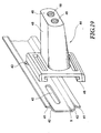
- the attachment is carried out by means of the fastening rail 9, which is essentially a U-shaped cross section with outward pointing end webs 41 on the U-legs 42.
- the mounting rail 9 is on the openings 43 on the Wall mountable.
- a fastening bolt can be pushed onto the fastening rail 9 44, which has a tapered plug-in section 45 and a C-shaped mounting plate at its thicker end 46 has.
- the mounting plate 46 is so in cross section designed that they laterally on the mounting rail 9th can be pushed on, but not removed perpendicular to the wall can be.
- the contour of the plug section 45 is to the inner contour of the Adjusted openings 15 in the molded body 1.
- the length of the Plug section 45, starting from the directly adjacent to this Surface 47 of the mounting plate 46 up to the end face 48 of the plug section 45 is slightly less than that Total thickness of the molded body 1 in the area of the receiving openings 15.
- the mounting plate 46 can be made in one piece with the Plug section 45 may be formed or manufactured separately and be attached to it.
- two threaded holes 49 and 50 are arranged in the end face 48 of the Plug section 45. These serve on the one hand to screw in the 1 shown threaded rods 11 and the other for screwing the fastening screws 51 (see also Fig. 1) for Attach the end plate 10 to the front 6 of the Shaped body 1.
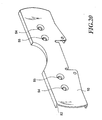
- the end plate 10 is shown in Fig. 20.
- the end plate 10 has a collar 52 which fits into a groove 53 engages on the front shell 2 (see Fig. 2) with a precise fit.
- the Holes 54 and 55 each serve to receive either Threaded rod 11 or the fastening screw 51, for which this are each provided with a countersink.
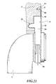
- 21 is now shown as a drain pipe 7 (see also FIG. 1) also on the molded body 1 soundproofing can be attached.
- the front shell points to this 2 on its front 6 the receiving pocket 23 in which a correspondingly shaped section of the pipe clamp 8 fits exactly and is flush with the front 6 of the front shell 2 completes.
- a screw 56 can Fastening can be used.
- the pipe clamp 8 is off Plastic made so that a soundproof suspension the drain pipe 7 is given. 21 is can also be seen very well, like the collar 52 of the end plate 10 engages in the groove 53 in the front shell 2.
- the Pipe clamp 8 is made in two parts and its lower part 8b can be attached to the upper part 8a, one area the drain pipe 7 is positively gripped. By this attachment will also be the sound absorbing suspension of the Drain pipe 7 brought about on the molded body 1.
- a mechanic will prefer the installation after the meter has been torn make.
- 1 markings can additionally be made on the molded body attached to facilitate alignment.
- Installation begins with the fastening of the fastening rail on the wall after the appropriate element positions and rail positions have been marked.
- the molded body 1 is large and is provided with a surface profile 12, 25 and 38, can be integrated into the wall structure. That means, that immediately plastering with mortar of the molding 1 and a subsequent tiling or bricking can take place.
- the rib structures 17 and 30 confer the installation element has sufficient strength, so that the attachment by means of the fastening bolts 44 in is generally sufficient.
- the upper area of the molded body 1 has sufficient strength because of this is also stabilized by the cistern 4. However, there is the possibility of also the upper section of the molded body 1 to fix on the wall again. Are preferred here soundproofing attachment means used.
- the toilet body After tiling, the toilet body can be attached become.
- the installation element according to the invention is in the assembly and of great advantage in manufacturing. At the same time adequate soundproofing is provided as all sound-generating parts arranged soundproofed in this or are held on this.
- the separate preforming of Half shells 2 is a crucial advance on this Area and results in significant cost savings.
- the self-supporting attachment can be designed in a variety of ways his. Because of the large number of possible combinations with regard to material composition, density, layer thickness and shapes in the field of plastics processing can the installation element the most different Properties are conferred.
Landscapes
- Life Sciences & Earth Sciences (AREA)
- Engineering & Computer Science (AREA)
- Hydrology & Water Resources (AREA)
- Public Health (AREA)
- Water Supply & Treatment (AREA)
- Health & Medical Sciences (AREA)
- Sanitary Device For Flush Toilet (AREA)
- Pipe Accessories (AREA)
- Building Environments (AREA)
- Bidet-Like Cleaning Device And Other Flush Toilet Accessories (AREA)
- Paper (AREA)
- Diaphragms For Electromechanical Transducers (AREA)
- Mattresses And Other Support Structures For Chairs And Beds (AREA)
Claims (23)
- Elément pour installation sanitaire comportant un corps façonné (1) qui est en un matériau isolant et dans lequel au moins un réservoir de chasse (4) avec tuyau d'évacuation (5) est agencé, caractérisé en ce que le corps façonné (1) est constitué d'au moins deux éléments formant coques (2, 3) qui sont adaptés au contour du réservoir de chasse (4) avec tuyau d'évacuation (5) et formés de manière à amortir le bruit et qui peuvent être assemblés de manière sensiblement ajustée pour entourer de manière correspondante le réservoir de chasse (4) avec tuyau d'évacuation (5), en ce que le corps façonné (1) comporte des ouvertures de réception (15) à une certaine distance du réservoir de chasse (4) avec tuyau d'évacuation (5) et en ce qu'il est prévu des moyens de fixation (44) qui servent à l'introduction dans l'ouverture de réception (15), notamment pour le montage mural.
- Elément pour installation sanitaire selon la revendication 1, caractérisé en ce qu'au moins une partie ou zone du réservoir de chasse (4) avec tuyau d'évacuation (5), notamment des parties ou zones stockant et conduisant l'eau, est formée par les éléments coques (2, 3) eux-mêmes.
- Elément pour installation sanitaire selon la revendication 1 ou 2, caractérisé en ce que les éléments coques (2, 3) sont assemblés, notamment dé manière étanche à l'eau, par l'intermédiaire d'éléments d'enfichage et de logement (21, 22 ; 34, 35) qui pénètrent les uns dans les autres avec friction.
- Elément pour installation sanitaire selon l'une des revendications 1 à 3, caractérisé en ce que le corps façonné (1) est conçu en au moins deux zones différentes avec des poids spécifiques différents c'est-à-dire des propriétés isolantes différentes.
- Elément pour installation sanitaire selon l'une des revendications 1 à 4, caractérisé en ce que le corps façonné (1) est construit en plusieurs couches.
- Elément pour installation sanitaire selon la revendication 4 ou 5, caractérisé en ce que les couches ou zones ont des propriétés différentes, par exemple densité, solidité, insonorisation ou ignifugation.
- Elément pour installation sanitaire selon l'une des revendications 1 à 6, caractérisé en ce qu'au moins l'avant (6) du corps façonné (1) est conçu essentiellement comme une grande surface de montage, notamment une surface pouvant être nettoyée et carrelée et est muni d'un profilage de surface (12).
- Elément pour installation sanitaire selon l'une des revendications 1 à 7, caractérisé en ce qu'au moins la zone autour des ouvertures de réception (15) du corps façonné (1) est conçue suffisamment stable pour donner un corps façonné (1) autoporteur.
- Elément pour installation sanitaire selon la revendication 8, caractérisé en ce que les ouvertures de réception (15) s'étendent de l'arrière à l'avant du corps façonné (1) à travers les éléments coques (2, 3) correspondants et en ce que les moyens de fixation (44) comportent sur leur côté frontal (48) accessible par l'avant des dispositifs de fixation (49, 50), notamment au moins un trou taraudé, par lesquels les charges venant de l'extérieur peuvent être pour l'essentiel supportées par les moyens de fixation (44).
- Elément pour installation sanitaire selon l'une des revendications 1 à 9, caractérisé en ce que les ouvertures de réception (15) se rétrécissent de l'arrière à l'avant du corps façonné (1) et en ce qu'il est prévu comme moyens de fixation des boulons de fixation (44) qui sont adaptés de manière appropriée dans le contour extérieur.
- Elément pour installation sanitaire selon l'une des revendications 1 à 10, caractérisé en ce que les moyens de fixation (44) comportent une surface de butée (47) pour l'appui à une zone arrière du corps façonné (1) et en ce qu'il est prévu une tôle de terminaison (10) qui est destinée à l'assemblage avec le côté frontal (48) des moyens de fixation (44) et qui vient s'appuyer à l'avant du corps façonné (1) de telle sorte que celui-ci est encastré entre les surfaces de butée (47) sur les moyens de fixation (44) et la tôle de terminaison (10).
- Elément pour installation sanitaire selon l'une des revendications 1 à 11, caractérisé en ce qu'il est prévu un rail de fixation (9) et en ce que les moyens de fixation (44) comportent des dispositifs de guidage (46) pour le coulissement latéral ou l'enfichage sur le rail de fixation (9) et pour le maintien dans la direction de charge du rail de fixation (9).
- Elément pour installation sanitaire selon la revendication 12, caractérisé en ce que des dispositifs d'arrêt sont prévus pour arrêter les moyens de fixation (44) sur le rail de fixation (9).
- Elément pour installation sanitaire selon l'une des revendications 1 à 13, caractérisé en ce que le corps façonné (1) est en plastique expansé, notamment en polystyrène.
- Elément pour installation sanitaire selon l'une des revendications 1 ou 14, caractérisé en ce qu'il est agencé à l'intérieur du corps façonné (1) des éléments à nervures (19, 27, 32) qui s'appuient de façon sensiblement ajustée, par zones, au réservoir de chasse (4) avec tuyau d'évacuation (5) et qui fixent celui-ci.
- Elément pour installation sanitaire selon l'une des revendications 1 à 15, caractérisé en ce que le corps façonné (1) est formé d'une caisse constituée de deux demi-coques (2, 3).
- Elément pour installation sanitaire selon la revendication 16, caractérisé en ce que le plan de séparation des deux demi-coques (2, 3) s'étend parallèlement à l'avant ou à l'arrière du corps façonné (1).
- Elément pour installation sanitaire selon l'une des revendications 1 à 17, caractérisé en ce qu'il est prévu au moins sur l'avant et/ou l'arrière du corps façonné (1) des poches façonnées (23) pour loger et/ou ajouter des éléments sanitaires supplémentaires (7) et/ou des dispositifs de fixation ou de pose (8).
- Elément pour installation sanitaire selon la revendication 18, caractérisé en ce qu'il est prévu un collier d'attache (8), un tuyau d'écoulement (7) et une poche façonnée (21) pour le placement du collier d'attache (8), le tuyau d'écoulement (7) étant monté de façon insonorisée.
- Elément pour installation sanitaire selon l'une des revendications 1 à 19, caractérisé en ce que des repères de montage sont formés sur le côté extérieur du corps façonné (1).
- Elément pour installation sanitaire selon l'une des revendications 18 à 20, caractérisé en ce qu'il est prévu dans la zone des poches façonnées (23) et/ou des zones de fixation du corps façonné (1) des parties en saillie déformables qui permettent une déformation graduelle en vue de l'ajustage dans l'état prémonté.
- Elément pour installation sanitaire selon l'une des revendications 1 à 21, caractérisé en ce qu'un moyen de fixation est prévu pour l'agencement dans la zone de bord supérieure du corps façonné (1).
- Corps façonné pour un élément pour installation sanitaire selon l'une des revendications 1 à 22, qui est constitué d'au moins deux éléments coques (2, 3) qui sont formés de manière à amortir le bruit sur les contours du réservoir de chasse (4) avec tuyau d'évacuation (5) et qui peuvent être assemblés de manière sensiblement ajustée pour entourer de manière correspondante le réservoir de chasse (4) avec tuyau d'évacuation (5) et qui comporte des ouvertures de réception (15) à une certaine distance des contours de logement pour le réservoir de chasse (4) avec tuyau d'évacuation (5) afin de loger des moyens de fixation (44) pour un montage mural.
Applications Claiming Priority (2)
| Application Number | Priority Date | Filing Date | Title |
|---|---|---|---|
| DE19635759 | 1996-09-03 | ||
| DE19635759A DE19635759A1 (de) | 1996-09-03 | 1996-09-03 | Installationselement für Sanitärinstallationen |
Publications (3)
| Publication Number | Publication Date |
|---|---|
| EP0826837A1 EP0826837A1 (fr) | 1998-03-04 |
| EP0826837B1 true EP0826837B1 (fr) | 2001-08-29 |
| EP0826837B2 EP0826837B2 (fr) | 2008-10-22 |
Family
ID=7804523
Family Applications (1)
| Application Number | Title | Priority Date | Filing Date |
|---|---|---|---|
| EP97112651A Expired - Lifetime EP0826837B2 (fr) | 1996-09-03 | 1997-07-23 | Elément pour installation sanitaire |
Country Status (5)
| Country | Link |
|---|---|
| EP (1) | EP0826837B2 (fr) |
| AT (1) | ATE204939T1 (fr) |
| DE (2) | DE19635759A1 (fr) |
| ES (1) | ES2163072T5 (fr) |
| PT (1) | PT826837E (fr) |
Cited By (1)
| Publication number | Priority date | Publication date | Assignee | Title |
|---|---|---|---|---|
| WO2022113067A1 (fr) | 2020-11-26 | 2022-06-02 | Zion Reuven | Paroi pour pavage |
Families Citing this family (5)
| Publication number | Priority date | Publication date | Assignee | Title |
|---|---|---|---|---|
| DE20211758U1 (de) * | 2002-07-31 | 2003-12-11 | Franz Viegener Ii Gmbh & Co. Kg | Installationseinheit |
| ES2401888B9 (es) * | 2011-09-21 | 2014-10-14 | Fominaya, S.A. | Bastidor empotrable para sujeción de elementos sanitarios y su proceso de fabricación |
| NO20150209A1 (en) * | 2015-02-12 | 2016-08-15 | Arvid Hanstad As | Concealed toilet cistern assembly |
| EP3067477B1 (fr) * | 2015-03-11 | 2019-05-08 | Raccords et Plastiques Nicoll | Dispositif de fixation pour bâti support, ensemble de fixation comprenant un tel dispositif et procédé de fixation sur un bâti support |
| FR3033581B1 (fr) * | 2015-03-11 | 2019-07-26 | Raccords Et Plastiques Nicoll | Bati support pour installation sanitaire du type encastree et procede de montage pour installation sanitaire du type encastree |
Citations (6)
| Publication number | Priority date | Publication date | Assignee | Title |
|---|---|---|---|---|
| DE1276561B (de) * | 1964-01-10 | 1968-08-29 | Hansa Metallwerke Ag | Installationswand |
| DE2637719A1 (de) * | 1976-08-21 | 1978-02-23 | Hansa Metallwerke Ag | Unterputz-armatur |
| DE3035935A1 (de) * | 1980-07-01 | 1982-02-04 | Similor S.A., 1227 Carouge, Geneve | Verbindungsstueck zwischen einem sanitaergeraet und einer wasserleitung |
| DE3445474A1 (de) * | 1984-12-13 | 1986-06-19 | SCHWAB Sanitär-Plastic GmbH, 7417 Pfullingen | Sanitaerbaustein |
| EP0646678A2 (fr) * | 1993-09-30 | 1995-04-05 | Emil Grumbach | Elément de construction d'installation préfabriquée |
| DE3907931C2 (de) * | 1989-03-13 | 1999-03-11 | Hansa Metallwerke Ag | Sanitäre Unterputzarmatur |
Family Cites Families (4)
| Publication number | Priority date | Publication date | Assignee | Title |
|---|---|---|---|---|
| DE3736679A1 (de) * | 1987-10-29 | 1989-05-11 | Anton Nachbar | Verbindungsanordnung zwischen einem sanitaergegenstand und wasserleitungsrohren, insbesondere zur installation an leichtbauwaenden |
| DE8907973U1 (de) * | 1989-06-29 | 1989-09-14 | Sanbloc GmbH, 8120 Weilheim | Installationsbaustein oder -block |
| DE4032257A1 (de) * | 1990-10-11 | 1992-04-16 | Mero Werke Kg | Installationseinrichtung |
| DE9116144U1 (de) * | 1991-02-27 | 1992-05-07 | Mero-Werke Dr.-Ing. Max Mengeringhausen GmbH & Co, 8700 Würzburg | Installationsblock |
-
1996
- 1996-09-03 DE DE19635759A patent/DE19635759A1/de not_active Withdrawn
-
1997
- 1997-07-23 DE DE59704427T patent/DE59704427D1/de not_active Expired - Lifetime
- 1997-07-23 PT PT97112651T patent/PT826837E/pt unknown
- 1997-07-23 ES ES97112651T patent/ES2163072T5/es not_active Expired - Lifetime
- 1997-07-23 EP EP97112651A patent/EP0826837B2/fr not_active Expired - Lifetime
- 1997-07-23 AT AT97112651T patent/ATE204939T1/de not_active IP Right Cessation
Patent Citations (6)
| Publication number | Priority date | Publication date | Assignee | Title |
|---|---|---|---|---|
| DE1276561B (de) * | 1964-01-10 | 1968-08-29 | Hansa Metallwerke Ag | Installationswand |
| DE2637719A1 (de) * | 1976-08-21 | 1978-02-23 | Hansa Metallwerke Ag | Unterputz-armatur |
| DE3035935A1 (de) * | 1980-07-01 | 1982-02-04 | Similor S.A., 1227 Carouge, Geneve | Verbindungsstueck zwischen einem sanitaergeraet und einer wasserleitung |
| DE3445474A1 (de) * | 1984-12-13 | 1986-06-19 | SCHWAB Sanitär-Plastic GmbH, 7417 Pfullingen | Sanitaerbaustein |
| DE3907931C2 (de) * | 1989-03-13 | 1999-03-11 | Hansa Metallwerke Ag | Sanitäre Unterputzarmatur |
| EP0646678A2 (fr) * | 1993-09-30 | 1995-04-05 | Emil Grumbach | Elément de construction d'installation préfabriquée |
Non-Patent Citations (2)
| Title |
|---|
| Prospekt der Firma Karl Grumbach 35581 Wetzlar Katalogblatt der Firma Schell 1/95 Blatt 2.3 Prospekt der Firma Ortwein 73061 Ebersbach Armaturen Katalog der Firma Hansa 95/1 * |
| Prospekt KARIBA, Listino N°2 Aprile 1995 * |
Cited By (2)
| Publication number | Priority date | Publication date | Assignee | Title |
|---|---|---|---|---|
| WO2022113067A1 (fr) | 2020-11-26 | 2022-06-02 | Zion Reuven | Paroi pour pavage |
| EP4251813A4 (fr) * | 2020-11-26 | 2024-09-18 | Zion, Reuven | Paroi pour pavage |
Also Published As
| Publication number | Publication date |
|---|---|
| ES2163072T3 (es) | 2002-01-16 |
| DE19635759A1 (de) | 1998-03-05 |
| EP0826837A1 (fr) | 1998-03-04 |
| DE59704427D1 (de) | 2001-10-04 |
| ES2163072T5 (es) | 2009-04-01 |
| ATE204939T1 (de) | 2001-09-15 |
| EP0826837B2 (fr) | 2008-10-22 |
| PT826837E (pt) | 2002-01-30 |
Similar Documents
| Publication | Publication Date | Title |
|---|---|---|
| EP0853753B1 (fr) | Module de montage pour installation sanitaire et son procede de fabrication | |
| EP0826837B1 (fr) | Elément pour installation sanitaire | |
| DE29918445U1 (de) | Verbundbauplatte für eine mit einer Installationsleitung versehene Wandung | |
| EP0495238B1 (fr) | Ensemble d'éléments de construction pour douches rondes | |
| DE3906758C2 (fr) | ||
| DE29623724U1 (de) | Installationselement für Sanitärinstallationen | |
| EP0662546A2 (fr) | Bloc de construction, pour la fixation d'installations et/ou appareils sanitaires sur une paroi | |
| DE19753339A1 (de) | Vorgefertigte Montagebox für den Heizungs- und Rohrleitungsbau sowie den Sanitärbereich und Einrichtung zu ihrer Herstellung | |
| DE102011054037B4 (de) | Formelement aus thermischem Isolationsmaterial mit wenigstens einer integrierten Installationsdose für elektrische bzw. elektrotechnische Geräte und Verfahren zu dessen Herstellung | |
| EP0166234A2 (fr) | Boîte de jonction pour installation de distribution d'eau | |
| DE29922263U1 (de) | Aussparungskörper für Betondecken | |
| DE19904394A1 (de) | Schachtelement zur Bildung eines in eine Gebäudewand integrierten Leerschachts | |
| DE9110913U1 (de) | Sanitärelement | |
| DE2447912A1 (de) | Abortbecken aus kunststoff | |
| DE19922646B4 (de) | Einbauvorrichtung | |
| EP0924829B1 (fr) | Dispositif de connexion pour conduites de câbles | |
| DE7920801U1 (de) | Raumhohes wandbauelement | |
| DE3338246A1 (de) | Fertigbauelement aus stahlbeton | |
| DE29822022U1 (de) | Vorgefertigte Montagebox für den Heizungs- und Rohrleitungsbau sowie den Sanitärbereich | |
| DE19949278A1 (de) | Verfahren zur Herstellung der Außenwände eines Massivhauses und Verbundschalung | |
| CH701113B1 (de) | Befestigungsvorrichtung für eine Abstandsbefestigung eines Gerätehalters an einer thermisch zu isolierenden Bauwerksoberfläche. | |
| AT407172B (de) | Formstein zur herstellung von mauerelementen | |
| CH663814A5 (de) | Bauelementensatz fuer die unterputzmontage von armaturen. | |
| DE8906225U1 (de) | Vorrichtung zum Abstützen und Verkleiden einer Badewanne od.dgl. | |
| DE4015342A1 (de) | Installationswand |
Legal Events
| Date | Code | Title | Description |
|---|---|---|---|
| PUAI | Public reference made under article 153(3) epc to a published international application that has entered the european phase |
Free format text: ORIGINAL CODE: 0009012 |
|
| AK | Designated contracting states |
Kind code of ref document: A1 Designated state(s): AT BE CH DE DK ES FI FR GB GR IE IT LI NL PT SE |
|
| AX | Request for extension of the european patent |
Free format text: AL;LT;LV;RO;SI |
|
| 17P | Request for examination filed |
Effective date: 19980520 |
|
| AKX | Designation fees paid |
Free format text: AT BE CH DE DK ES FI FR GB GR IE IT LI NL PT SE |
|
| RBV | Designated contracting states (corrected) |
Designated state(s): AT BE CH DE DK ES FI FR GB GR IE IT LI NL PT SE |
|
| 17Q | First examination report despatched |
Effective date: 19990414 |
|
| GRAG | Despatch of communication of intention to grant |
Free format text: ORIGINAL CODE: EPIDOS AGRA |
|
| 17Q | First examination report despatched |
Effective date: 19990414 |
|
| GRAG | Despatch of communication of intention to grant |
Free format text: ORIGINAL CODE: EPIDOS AGRA |
|
| GRAG | Despatch of communication of intention to grant |
Free format text: ORIGINAL CODE: EPIDOS AGRA |
|
| GRAH | Despatch of communication of intention to grant a patent |
Free format text: ORIGINAL CODE: EPIDOS IGRA |
|
| GRAH | Despatch of communication of intention to grant a patent |
Free format text: ORIGINAL CODE: EPIDOS IGRA |
|
| GRAA | (expected) grant |
Free format text: ORIGINAL CODE: 0009210 |
|
| RAP1 | Party data changed (applicant data changed or rights of an application transferred) |
Owner name: DAL GMBH & CO. GMBH |
|
| RAP1 | Party data changed (applicant data changed or rights of an application transferred) |
Owner name: DAL GMBH & CO.KG |
|
| AK | Designated contracting states |
Kind code of ref document: B1 Designated state(s): AT BE CH DE DK ES FI FR GB GR IE IT LI NL PT SE |
|
| PG25 | Lapsed in a contracting state [announced via postgrant information from national office to epo] |
Ref country code: IE Free format text: LAPSE BECAUSE OF FAILURE TO SUBMIT A TRANSLATION OF THE DESCRIPTION OR TO PAY THE FEE WITHIN THE PRESCRIBED TIME-LIMIT Effective date: 20010829 Ref country code: FI Free format text: LAPSE BECAUSE OF FAILURE TO SUBMIT A TRANSLATION OF THE DESCRIPTION OR TO PAY THE FEE WITHIN THE PRESCRIBED TIME-LIMIT Effective date: 20010829 |
|
| REF | Corresponds to: |
Ref document number: 204939 Country of ref document: AT Date of ref document: 20010915 Kind code of ref document: T |
|
| REG | Reference to a national code |
Ref country code: CH Ref legal event code: NV Representative=s name: BOVARD AG PATENTANWAELTE Ref country code: CH Ref legal event code: EP |
|
| REG | Reference to a national code |
Ref country code: IE Ref legal event code: FG4D Free format text: GERMAN |
|
| REF | Corresponds to: |
Ref document number: 59704427 Country of ref document: DE Date of ref document: 20011004 |
|
| GBT | Gb: translation of ep patent filed (gb section 77(6)(a)/1977) |
Effective date: 20011030 |
|
| PG25 | Lapsed in a contracting state [announced via postgrant information from national office to epo] |
Ref country code: DK Free format text: LAPSE BECAUSE OF FAILURE TO SUBMIT A TRANSLATION OF THE DESCRIPTION OR TO PAY THE FEE WITHIN THE PRESCRIBED TIME-LIMIT Effective date: 20011129 |
|
| PG25 | Lapsed in a contracting state [announced via postgrant information from national office to epo] |
Ref country code: GR Free format text: LAPSE BECAUSE OF FAILURE TO SUBMIT A TRANSLATION OF THE DESCRIPTION OR TO PAY THE FEE WITHIN THE PRESCRIBED TIME-LIMIT Effective date: 20011130 |
|
| REG | Reference to a national code |
Ref country code: GB Ref legal event code: IF02 |
|
| ET | Fr: translation filed | ||
| REG | Reference to a national code |
Ref country code: ES Ref legal event code: FG2A Ref document number: 2163072 Country of ref document: ES Kind code of ref document: T3 |
|
| REG | Reference to a national code |
Ref country code: PT Ref legal event code: SC4A Free format text: AVAILABILITY OF NATIONAL TRANSLATION Effective date: 20011023 |
|
| REG | Reference to a national code |
Ref country code: IE Ref legal event code: FD4D |
|
| PLBI | Opposition filed |
Free format text: ORIGINAL CODE: 0009260 |
|
| 26 | Opposition filed |
Opponent name: CREVAN S.R.L. Effective date: 20020527 |
|
| PLAB | Opposition data, opponent's data or that of the opponent's representative modified |
Free format text: ORIGINAL CODE: 0009299OPPO |
|
| PLBF | Reply of patent proprietor to notice(s) of opposition |
Free format text: ORIGINAL CODE: EPIDOS OBSO |
|
| PLBQ | Unpublished change to opponent data |
Free format text: ORIGINAL CODE: EPIDOS OPPO |
|
| NLR1 | Nl: opposition has been filed with the epo |
Opponent name: CREVAN S.R.L. |
|
| R26 | Opposition filed (corrected) |
Opponent name: CREVAN S.R.L. Effective date: 20020527 |
|
| NLR1 | Nl: opposition has been filed with the epo |
Opponent name: CREVAN S.R.L. |
|
| PLBF | Reply of patent proprietor to notice(s) of opposition |
Free format text: ORIGINAL CODE: EPIDOS OBSO |
|
| PLBF | Reply of patent proprietor to notice(s) of opposition |
Free format text: ORIGINAL CODE: EPIDOS OBSO |
|
| PLBQ | Unpublished change to opponent data |
Free format text: ORIGINAL CODE: EPIDOS OPPO |
|
| PLAB | Opposition data, opponent's data or that of the opponent's representative modified |
Free format text: ORIGINAL CODE: 0009299OPPO |
|
| R26 | Opposition filed (corrected) |
Opponent name: CREVAN S.R.L. Effective date: 20020527 |
|
| NLR1 | Nl: opposition has been filed with the epo |
Opponent name: CREVAN S.R.L. |
|
| PLAB | Opposition data, opponent's data or that of the opponent's representative modified |
Free format text: ORIGINAL CODE: 0009299OPPO |
|
| PLAQ | Examination of admissibility of opposition: information related to despatch of communication + time limit deleted |
Free format text: ORIGINAL CODE: EPIDOSDOPE2 |
|
| PLAR | Examination of admissibility of opposition: information related to receipt of reply deleted |
Free format text: ORIGINAL CODE: EPIDOSDOPE4 |
|
| PLBQ | Unpublished change to opponent data |
Free format text: ORIGINAL CODE: EPIDOS OPPO |
|
| RDAF | Communication despatched that patent is revoked |
Free format text: ORIGINAL CODE: EPIDOSNREV1 |
|
| R26 | Opposition filed (corrected) |
Opponent name: CREVAN S.R.L. Effective date: 20020527 |
|
| APBP | Date of receipt of notice of appeal recorded |
Free format text: ORIGINAL CODE: EPIDOSNNOA2O |
|
| APBM | Appeal reference recorded |
Free format text: ORIGINAL CODE: EPIDOSNREFNO |
|
| NLR1 | Nl: opposition has been filed with the epo |
Opponent name: CREVAN S.R.L. |
|
| APBQ | Date of receipt of statement of grounds of appeal recorded |
Free format text: ORIGINAL CODE: EPIDOSNNOA3O |
|
| APAH | Appeal reference modified |
Free format text: ORIGINAL CODE: EPIDOSCREFNO |
|
| PLAB | Opposition data, opponent's data or that of the opponent's representative modified |
Free format text: ORIGINAL CODE: 0009299OPPO |
|
| R26 | Opposition filed (corrected) |
Opponent name: CREVAN S.R.L. Effective date: 20020527 |
|
| APBU | Appeal procedure closed |
Free format text: ORIGINAL CODE: EPIDOSNNOA9O |
|
| NLR1 | Nl: opposition has been filed with the epo |
Opponent name: CREVAN S.R.L. |
|
| PLAB | Opposition data, opponent's data or that of the opponent's representative modified |
Free format text: ORIGINAL CODE: 0009299OPPO |
|
| R26 | Opposition filed (corrected) |
Opponent name: CREVAN S.R.L. Effective date: 20020527 |
|
| PUAH | Patent maintained in amended form |
Free format text: ORIGINAL CODE: 0009272 |
|
| STAA | Information on the status of an ep patent application or granted ep patent |
Free format text: STATUS: PATENT MAINTAINED AS AMENDED |
|
| 27A | Patent maintained in amended form |
Effective date: 20081022 |
|
| AK | Designated contracting states |
Kind code of ref document: B2 Designated state(s): AT BE CH DE DK ES FI FR GB GR IE IT LI NL PT SE |
|
| REG | Reference to a national code |
Ref country code: CH Ref legal event code: AEN Free format text: AUFRECHTERHALTUNG DES PATENTES IN GEAENDERTER FORM |
|
| NLR1 | Nl: opposition has been filed with the epo |
Opponent name: CREVAN S.R.L. |
|
| NLR2 | Nl: decision of opposition |
Effective date: 20081022 |
|
| REG | Reference to a national code |
Ref country code: SE Ref legal event code: RPEO |
|
| NLR3 | Nl: receipt of modified translations in the netherlands language after an opposition procedure | ||
| REG | Reference to a national code |
Ref country code: ES Ref legal event code: DC2A Date of ref document: 20090113 Kind code of ref document: T5 |
|
| PGFP | Annual fee paid to national office [announced via postgrant information from national office to epo] |
Ref country code: NL Payment date: 20100714 Year of fee payment: 14 Ref country code: CH Payment date: 20100726 Year of fee payment: 14 |
|
| PGFP | Annual fee paid to national office [announced via postgrant information from national office to epo] |
Ref country code: SE Payment date: 20100715 Year of fee payment: 14 Ref country code: IT Payment date: 20100727 Year of fee payment: 14 Ref country code: FR Payment date: 20100805 Year of fee payment: 14 Ref country code: AT Payment date: 20100714 Year of fee payment: 14 |
|
| PGFP | Annual fee paid to national office [announced via postgrant information from national office to epo] |
Ref country code: GB Payment date: 20100722 Year of fee payment: 14 |
|
| PGFP | Annual fee paid to national office [announced via postgrant information from national office to epo] |
Ref country code: PT Payment date: 20100716 Year of fee payment: 14 |
|
| PGFP | Annual fee paid to national office [announced via postgrant information from national office to epo] |
Ref country code: BE Payment date: 20100715 Year of fee payment: 14 |
|
| REG | Reference to a national code |
Ref country code: CH Ref legal event code: PFA Owner name: DAL GMBH & CO.KG Free format text: DAL GMBH & CO.KG#ZUR PORTA 8-12#32457 PORTA WESTFALICA (DE) -TRANSFER TO- DAL GMBH & CO.KG#ZUR PORTA 8-12#32457 PORTA WESTFALICA (DE) |
|
| REG | Reference to a national code |
Ref country code: PT Ref legal event code: MM4A Free format text: LAPSE DUE TO NON-PAYMENT OF FEES Effective date: 20120123 |
|
| BERE | Be: lapsed |
Owner name: *DAL G.M.B.H. & CO. K.G. Effective date: 20110731 |
|
| REG | Reference to a national code |
Ref country code: NL Ref legal event code: V1 Effective date: 20120201 |
|
| REG | Reference to a national code |
Ref country code: CH Ref legal event code: PL |
|
| REG | Reference to a national code |
Ref country code: SE Ref legal event code: EUG |
|
| GBPC | Gb: european patent ceased through non-payment of renewal fee |
Effective date: 20110723 |
|
| REG | Reference to a national code |
Ref country code: AT Ref legal event code: MM01 Ref document number: 204939 Country of ref document: AT Kind code of ref document: T Effective date: 20110723 |
|
| REG | Reference to a national code |
Ref country code: FR Ref legal event code: ST Effective date: 20120330 |
|
| PG25 | Lapsed in a contracting state [announced via postgrant information from national office to epo] |
Ref country code: CH Free format text: LAPSE BECAUSE OF NON-PAYMENT OF DUE FEES Effective date: 20110731 Ref country code: LI Free format text: LAPSE BECAUSE OF NON-PAYMENT OF DUE FEES Effective date: 20110731 Ref country code: BE Free format text: LAPSE BECAUSE OF NON-PAYMENT OF DUE FEES Effective date: 20110731 Ref country code: FR Free format text: LAPSE BECAUSE OF NON-PAYMENT OF DUE FEES Effective date: 20110801 |
|
| PG25 | Lapsed in a contracting state [announced via postgrant information from national office to epo] |
Ref country code: PT Free format text: LAPSE BECAUSE OF NON-PAYMENT OF DUE FEES Effective date: 20120123 Ref country code: IT Free format text: LAPSE BECAUSE OF NON-PAYMENT OF DUE FEES Effective date: 20110723 Ref country code: NL Free format text: LAPSE BECAUSE OF NON-PAYMENT OF DUE FEES Effective date: 20120201 |
|
| PG25 | Lapsed in a contracting state [announced via postgrant information from national office to epo] |
Ref country code: GB Free format text: LAPSE BECAUSE OF NON-PAYMENT OF DUE FEES Effective date: 20110723 |
|
| PG25 | Lapsed in a contracting state [announced via postgrant information from national office to epo] |
Ref country code: AT Free format text: LAPSE BECAUSE OF NON-PAYMENT OF DUE FEES Effective date: 20110723 |
|
| PG25 | Lapsed in a contracting state [announced via postgrant information from national office to epo] |
Ref country code: SE Free format text: LAPSE BECAUSE OF NON-PAYMENT OF DUE FEES Effective date: 20110724 |
|
| PGFP | Annual fee paid to national office [announced via postgrant information from national office to epo] |
Ref country code: ES Payment date: 20150728 Year of fee payment: 19 |
|
| PGFP | Annual fee paid to national office [announced via postgrant information from national office to epo] |
Ref country code: DE Payment date: 20160722 Year of fee payment: 20 |
|
| REG | Reference to a national code |
Ref country code: DE Ref legal event code: R071 Ref document number: 59704427 Country of ref document: DE |
|
| REG | Reference to a national code |
Ref country code: ES Ref legal event code: FD2A Effective date: 20180507 |
|
| PG25 | Lapsed in a contracting state [announced via postgrant information from national office to epo] |
Ref country code: ES Free format text: LAPSE BECAUSE OF NON-PAYMENT OF DUE FEES Effective date: 20160724 |