EP0826838A2 - Vakuumventilregler - Google Patents
Vakuumventilregler Download PDFInfo
- Publication number
- EP0826838A2 EP0826838A2 EP97114618A EP97114618A EP0826838A2 EP 0826838 A2 EP0826838 A2 EP 0826838A2 EP 97114618 A EP97114618 A EP 97114618A EP 97114618 A EP97114618 A EP 97114618A EP 0826838 A2 EP0826838 A2 EP 0826838A2
- Authority
- EP
- European Patent Office
- Prior art keywords
- vacuum valve
- vacuum
- actuating means
- soil water
- pressure
- Prior art date
- Legal status (The legal status is an assumption and is not a legal conclusion. Google has not performed a legal analysis and makes no representation as to the accuracy of the status listed.)
- Granted
Links
Images

Classifications
-
- E—FIXED CONSTRUCTIONS
- E03—WATER SUPPLY; SEWERAGE
- E03F—SEWERS; CESSPOOLS
- E03F1/00—Methods, systems, or installations for draining-off sewage or storm water
- E03F1/006—Pneumatic sewage disposal systems; accessories specially adapted therefore
-
- Y—GENERAL TAGGING OF NEW TECHNOLOGICAL DEVELOPMENTS; GENERAL TAGGING OF CROSS-SECTIONAL TECHNOLOGIES SPANNING OVER SEVERAL SECTIONS OF THE IPC; TECHNICAL SUBJECTS COVERED BY FORMER USPC CROSS-REFERENCE ART COLLECTIONS [XRACs] AND DIGESTS
- Y10—TECHNICAL SUBJECTS COVERED BY FORMER USPC
- Y10S—TECHNICAL SUBJECTS COVERED BY FORMER USPC CROSS-REFERENCE ART COLLECTIONS [XRACs] AND DIGESTS
- Y10S137/00—Fluid handling
- Y10S137/907—Vacuum-actuated valves
-
- Y—GENERAL TAGGING OF NEW TECHNOLOGICAL DEVELOPMENTS; GENERAL TAGGING OF CROSS-SECTIONAL TECHNOLOGIES SPANNING OVER SEVERAL SECTIONS OF THE IPC; TECHNICAL SUBJECTS COVERED BY FORMER USPC CROSS-REFERENCE ART COLLECTIONS [XRACs] AND DIGESTS
- Y10—TECHNICAL SUBJECTS COVERED BY FORMER USPC
- Y10T—TECHNICAL SUBJECTS COVERED BY FORMER US CLASSIFICATION
- Y10T137/00—Fluid handling
- Y10T137/2931—Diverse fluid containing pressure systems
- Y10T137/3109—Liquid filling by evacuating container
-
- Y—GENERAL TAGGING OF NEW TECHNOLOGICAL DEVELOPMENTS; GENERAL TAGGING OF CROSS-SECTIONAL TECHNOLOGIES SPANNING OVER SEVERAL SECTIONS OF THE IPC; TECHNICAL SUBJECTS COVERED BY FORMER USPC CROSS-REFERENCE ART COLLECTIONS [XRACs] AND DIGESTS
- Y10—TECHNICAL SUBJECTS COVERED BY FORMER USPC
- Y10T—TECHNICAL SUBJECTS COVERED BY FORMER US CLASSIFICATION
- Y10T137/00—Fluid handling
- Y10T137/402—Distribution systems involving geographic features
-
- Y—GENERAL TAGGING OF NEW TECHNOLOGICAL DEVELOPMENTS; GENERAL TAGGING OF CROSS-SECTIONAL TECHNOLOGIES SPANNING OVER SEVERAL SECTIONS OF THE IPC; TECHNICAL SUBJECTS COVERED BY FORMER USPC CROSS-REFERENCE ART COLLECTIONS [XRACs] AND DIGESTS
- Y10—TECHNICAL SUBJECTS COVERED BY FORMER USPC
- Y10T—TECHNICAL SUBJECTS COVERED BY FORMER US CLASSIFICATION
- Y10T137/00—Fluid handling
- Y10T137/7287—Liquid level responsive or maintaining systems
- Y10T137/731—With control fluid connection at desired liquid level
-
- Y—GENERAL TAGGING OF NEW TECHNOLOGICAL DEVELOPMENTS; GENERAL TAGGING OF CROSS-SECTIONAL TECHNOLOGIES SPANNING OVER SEVERAL SECTIONS OF THE IPC; TECHNICAL SUBJECTS COVERED BY FORMER USPC CROSS-REFERENCE ART COLLECTIONS [XRACs] AND DIGESTS
- Y10—TECHNICAL SUBJECTS COVERED BY FORMER USPC
- Y10T—TECHNICAL SUBJECTS COVERED BY FORMER US CLASSIFICATION
- Y10T137/00—Fluid handling
- Y10T137/7287—Liquid level responsive or maintaining systems
- Y10T137/7313—Control of outflow from tank
-
- Y—GENERAL TAGGING OF NEW TECHNOLOGICAL DEVELOPMENTS; GENERAL TAGGING OF CROSS-SECTIONAL TECHNOLOGIES SPANNING OVER SEVERAL SECTIONS OF THE IPC; TECHNICAL SUBJECTS COVERED BY FORMER USPC CROSS-REFERENCE ART COLLECTIONS [XRACs] AND DIGESTS
- Y10—TECHNICAL SUBJECTS COVERED BY FORMER USPC
- Y10T—TECHNICAL SUBJECTS COVERED BY FORMER US CLASSIFICATION
- Y10T137/00—Fluid handling
- Y10T137/7287—Liquid level responsive or maintaining systems
- Y10T137/7313—Control of outflow from tank
- Y10T137/7316—Self-emptying tanks
-
- Y—GENERAL TAGGING OF NEW TECHNOLOGICAL DEVELOPMENTS; GENERAL TAGGING OF CROSS-SECTIONAL TECHNOLOGIES SPANNING OVER SEVERAL SECTIONS OF THE IPC; TECHNICAL SUBJECTS COVERED BY FORMER USPC CROSS-REFERENCE ART COLLECTIONS [XRACs] AND DIGESTS
- Y10—TECHNICAL SUBJECTS COVERED BY FORMER USPC
- Y10T—TECHNICAL SUBJECTS COVERED BY FORMER US CLASSIFICATION
- Y10T137/00—Fluid handling
- Y10T137/7287—Liquid level responsive or maintaining systems
- Y10T137/7339—By weight of accumulated fluid
Definitions
- the present invention relates to a vacuum valve controller for controlling a vacuum valve for use in a vacuum transfer system for transferring soil water accumulated in a soil water basin to a predetermined place, such as a sewage disposal plant.
- the vacuum transfer system sucks the soil water from the soil water basin through a suction pipe by opening the vacuum valve.
- each soil water basin is provided with a soil water suction pipe, a vacuum valve for selectively communicating the suction pipe with a vacuum system and a vacuum valve controller for controlling the vacuum valve to open and close depending on the level of the soil water accumulated in the soil water basin.
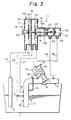
- FIGs. 3 and 4 show an exemplified system arrangement using a prior art vacuum valve controller of the type described above, which is disclosed in Japanese Patent Application No. Hei-7-39362 (No. 39362/1995).
- reference numeral 1 denotes a soil water basin, which is provided with a suction pipe 3 having a distal end disposed in the soil water basin 1 and a proximal end connected to a line 5 (forming a part of a vacuum system) through a vacuum valve 4 having a valve body 6.
- the line 5 is in communication with a vacuum tank (not shown).
- the vacuum valve 4 further includes a diaphragm 4b and a spring 4a for biasing the diaphragm 4b, both housed in a piston chamber 4c.
- Reference numeral 11 denotes a controller, which comprises a casing 12 having a large-diameter portion 12a and a smaller-diameter portion 12b contiguous to the larger-diameter portion 12a.
- the larger-diameter portion 12a has a partition wall 15 formed therein substantially at the center of the larger-diameter portion 12a and dividing the inside of the larger-diameter portion 12a into left- and right-hand regions.
- the partition wall 15 has a hole formed therein through which extends a shaft 14 supporting a valve body 13.
- the left-hand region is divided into first and second pressure chambers 17 and 18 by means of a first diaphragm or a sensor diaphragm 16 provided substantially at the center of the left-hand region.
- the right-hand region is divided into third and fourth pressure chambers 20 and 21 by means of a second diaphragm 19 provided substantially at the center of the right-hand region.
- the inside of the smaller-diameter portion 12b is divided into left- and right-hand regions by means of a partition wall 22.
- the left-hand region of the smaller-diameter portion 12b defines a chamber which is contiguous to and in communication with the fourth chamber 21.
- the right-hand region of the smaller-diameter portion 12b is divided into fifth and sixth pressure chambers 24 and 25 by means of a partition wall 23.
- the proximal end of the shaft 14 is fixedly secured to the first diaphragm 16 at the center thereof by means of a screw 14a.
- the shaft 14 extends through the partition wall 15, as well as through the second diaphragm 19 (which is fixedly secured to the shaft 14).
- the shaft 14 further extends through the partition walls 22 and 23.
- a seal 26 is provided between the shaft 14 and the partition wall 15 and another seal 27 is provided between the shaft 14 and the partition wall 22.
- the partition wall 23 has a through hole 23a formed therein, through which the shaft 14 extends, and which may be closed by the valve body 13.
- a spring 28 is provided for urging the second diaphragm 19 in a leftward direction seen in the figure.
- a magnet 29 is provided on the rear end wall of the casing 12 at a position where it faces the rear end (or the proximal end) of the shaft 14, and more specifically the above-mentioned screw 14a made of a suitable ferromagnetic material and which is threadingly secured to the rear end of the shaft 14.
- the sixth chamber 25 has a hole 30 for communicating with the atmosphere, which may be opened or closed by the valve body 13.
- the suction pipe 3 has pressure detection holes 9 and 10 provided at different levels, with a predetermined spacing in the vertical direction defined between the holes 9 and 10.
- One pressure detection hole 9 is in communication with the fourth chamber 21 through a pipe 31, while the other pressure detection hole 10 is in communication with the third chamber 20 through a pipe 32.
- a pressure sensing tube 2 is disposed in the soil water basin 1 and in communication with the first chamber 17 through a pipe 33.
- the second chamber 18 is in communication with the atmosphere through a hole 34.
- the fifth chamber 24 is in communication with the line 5 through a pipe 35 and the sixth chamber 25 is in communication with the piston chamber 4c of the vacuum valve 4 through a pipe 36.
- the vacuum valve controller having the above arrangement, as the level of soil water in the soil water basin 1 rises, the pressure in the pressure sensing tube 2 builds up, and this pressure is led through the pipe 33 into the first chamber 17 in the controller 11.
- the first diaphragm 16 is displaced in the rightward direction against the biasing force of the spring 28 as well as against the magnetic attraction force of the magnet 29, so that the shaft 14 is displaced in the right direction to cause the valve body 13 to close the hole 30 communicating with the atmosphere.
- the vacuum in the line 5 is led through the pipe 35 into the fifth and sixth chambers 24 and 25, and thence into the piston chamber 4c of the vacuum valve 4.
- the valve body of the vacuum valve 4 is lifted away from the valve seat 7.
- the valve body 13 remains pressed against the hole 30 by virtue of the rightward force provided by the pressure difference between the fourth and third chambers 21 and 20.
- the pressure difference lasts as long as soil water flows into the line 5 through the suction pipe 3.
- the prior art vacuum valve controller having the arrangement described above, however, suffers from a problem as follows. Namely, in a case where a leakage occurs in the pressure sending tube 2 and when a water level in the basin 1 is lowered, a soil water column may be formed in the pressure sensing tube 2. In another case, it is also possible that the vacuum valve controller 11 and the pressure sensing tube 2 are initially connected to each other with a soil water column inadvertently left in the pressure sensing tube 2. In either case, the pressure in the pressure sensing tube 2 becomes negative when the soil water in the basin 1 is sucked through the vacuum valve 4, thereby lowering the soil water level in the basin 1 to a certain level near the lower end of the suction pipe 3.
- the first diaphragm 16 may be displaced back to its standby position or leftward limit position forcibly. If this occurs, the shaft 14 is also moved back to its standby position, and, thus, the valve body 6 of the vacuum valve 4 forcibly closes the valve port in the valve seat 7 while the soil water is sucked from the basin 1. This results in an occurrence of water-hammer in a region of the vacuum valve 4 upstream of the valve body 6, which leads to a possible, unintended disconnection of the vacuum valve 4 from the suction pipe 3.
- a vacuum valve controller for controlling a vacuum valve, which can prevent any forced closing of the vacuum valve during suction of soil water from a soil water basin, even when a soil water column is formed in a pressure sensing tube due to a possible leakage occurring in the sensing tube or for some other reason, and which ensures that the vacuum valve is actuated to close only after air is sucked through the suction pipe.
- the vacuum valve controller for a vacuum sewer system having a suction pipe which is communicated with a vacuum system by opening a vacuum valve, and which is cut off from the vacuum system by closing the vacuum valve, so that soil water in a soil water basin is sucked through the suction pipe and sent to a predetermined place by opening said vacuum valve
- the vacuum valve controller comprises a vacuum valve actuating means which is movable between a first position and a second position for actuating the vacuum valve between an open position and a closed position, respectively, means for normally biasing the vacuum valve actuating means to the second position, a pressure sensing tube for converting a change in level of soil water in the soil water basin to a change in pressure, a first pressure chamber com-municated with the pressure sensing tube and associated with the vacuum value actuating means for moving the vacuum valve actuating means to the first position when a level in the soil water basin reaches a predetermined level, and means for urging the vacuum valve actuating means to the second position while
- the first pressure chamber is so associated with the vacuum valve actuating means that the pressure chamber is capable of moving the vacuum valve actuating means to the first position while being incapable of moving the vacuum valve actuating means to the second position.
- the vacuum valve actuating means may be constituted so that it includes a valve means for selectively communicating a piston chamber of the vacuum valve to a vacuum source or an atmosphere to open or close the vacuum valve, and a reciprocable shaft supporting the switching valve.
- the vacuum source may be provided from the vacuum system positioned down-stream of the vacuum valve.
- the first pressure chamber includes a first pressure responsive diaphragm and the diaphragm is separated from the shaft of the vacuum valve actuating means so that the diaphragm is capable of pushing the shaft to move the vacuum valve actuating means to the first position, while it is incapable of pulling the shaft to move the vacuum valve actuating means to the second position.
- the means for urging the vacuum valve actuating means comprises a second pressure responsive diaphragm associated with the reciprocable shaft, and a pair of pressure chambers are provided on both sides of the second diaphragm.
- the pressures in the suction pipe at different levels are led into the pair of pressure chambers provided on both sides of the second diaphragm so that a pressure difference therebetween serves to move the vacuum valve actuating means to the first position against a force of the biasing means.
- the first diaphragm is preferably made of a ferromagnetic material, and a magnet is provided in the first pressure chamber facing the first diaphragm so that magnetic attraction force is applied to the first diaphragm in the direction away from the reciprocable shaft.
- the vacuum valve actuating means, the reciprocable shaft, the first and second pressure chambers, and the first and second diaphragms are preferably received in a single casing.
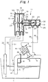
- Fig. 1 shows a system arrangement using a vacuum valve controller of the present invention
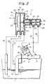
- Fig. 2 illustrates the operation of the vacuum valve controller when the pressure in the pressure sending tube becomes negative, which is experienced when a soil water column is formed in the pressure sensing tube due to, for example, a leak in the pressure sensing tube and, then, the soil water level in the soil water basin is lowered by sucking the soil water through the vacuum valve.
- the arrangement of the vacuum valve controller according to the present invention shown in Fig. 1 is similar to that of the prior art vacuum valve controller shown in Figs. 3 and 4 except for the following point.
- the rear or left end of the shaft 14 is fixedly secured to the first diaphragm 16 at the center thereof by means of the securing screw 14a (formed of a ferromagnetic material)
- the rear end of the shaft 14 and the first diaphragm 16 (made of a ferromagnetic material) are separated or unconnected from each other.
- the first diaphragm 16 is capable of acting on the shaft 14 so as to move the shaft 14 in a rightward direction while being incapable of acting on the shaft 14 so as to move the shaft 14 in a leftward direction.
- the vacuum valve controller of Fig. 1 having the above arrangement, as the level of the soil water in the soil water basin 1 rises, the pressure in the pressure sensing tube 2 builds up, and this pressure is led through the pipe 33 into the first chamber 17 in the controller 11.
- the first diaphragm 16 (made of a ferromagnetic material) is displaced in a rightward direction against the biasing force provided by the spring 28 as well as against the attraction force provided by the magnet 29, so that the shaft 14 is pushed by the first diaphragm 16 in this direction to cause the valve body 13 to close the hole 30 communicating with the atmosphere.
- the vacuum in the line 5 is led through the pipe 35 into the fifth and sixth chambers 24 and 25, and thence into the piston chamber 4c of the vacuum valve 4 through the pipe 36.
- the valve body 6 of the vacuum valve 4 is lifted away from the valve seat 7.
- a soil water column may be formed in the pressure sensing tube 2 while the vacuum valve 4 is open so as to start sucking the soil water from the soil water basin 1. This may occur, for example, due to a possible leakage occurring in the pressure sensing tube 2 In such a case, the soil water level in the pressure sensing tube 2 may become higher than that in thesoil water basin 1 after some amount of soil water is sucked out of the basin 1, as shown in Fig. 2, leading to a negative pressure produced in the pressure sensing tube 2. This lowers the pressure in the first chamber 17, resulting in displacement of the sensor diaphragm 16 in a leftward direction.
- the vacuum valve controller of the present invention allows no water-hammer to occur in a region of the vacuum valve 4 upstream of the valve body 6, and is free from any problems which could result from such water-hammer.
- the first diaphragm and the shaft are separate from each other, the first diaphragm is capable of acting on the shaft in a direction for opening the vacuum valve while being incapable of acting on the shaft in a direction for closing the vacuum valve.
- the first diaphragm is capable of acting on the shaft in a direction for opening the vacuum valve while being incapable of acting on the shaft in a direction for closing the vacuum valve.
- the invention relates to a vacuum valve controller for a vacuum sewer system having a suction pipe which is communicated with a vacuum system by opening a vacuum valve, and which is cut off from the vacuum system by closing said vacuum valve, said vacuum valve controller comprising:
Landscapes
- Health & Medical Sciences (AREA)
- Life Sciences & Earth Sciences (AREA)
- Engineering & Computer Science (AREA)
- Hydrology & Water Resources (AREA)
- Public Health (AREA)
- Water Supply & Treatment (AREA)
- Sewage (AREA)
- Fluid-Driven Valves (AREA)
Applications Claiming Priority (3)
| Application Number | Priority Date | Filing Date | Title |
|---|---|---|---|
| JP24419496 | 1996-08-26 | ||
| JP24419496A JP3286535B2 (ja) | 1996-08-26 | 1996-08-26 | 真空弁制御装置 |
| JP244194/96 | 1996-08-26 |
Publications (3)
| Publication Number | Publication Date |
|---|---|
| EP0826838A2 true EP0826838A2 (de) | 1998-03-04 |
| EP0826838A3 EP0826838A3 (de) | 1998-03-11 |
| EP0826838B1 EP0826838B1 (de) | 2004-11-03 |
Family
ID=17115182
Family Applications (1)
| Application Number | Title | Priority Date | Filing Date |
|---|---|---|---|
| EP97114618A Expired - Lifetime EP0826838B1 (de) | 1996-08-26 | 1997-08-22 | Vakuumventilregler |
Country Status (6)
| Country | Link |
|---|---|
| US (1) | US5871027A (de) |
| EP (1) | EP0826838B1 (de) |
| JP (1) | JP3286535B2 (de) |
| KR (1) | KR100477773B1 (de) |
| CN (1) | CN1090271C (de) |
| MY (1) | MY118911A (de) |
Cited By (3)
| Publication number | Priority date | Publication date | Assignee | Title |
|---|---|---|---|---|
| EP2415938A4 (de) * | 2009-04-03 | 2014-03-19 | Torishima Pump Mfg Co Ltd | Steuervorrichtung für vakuumventil |
| WO2015144904A1 (de) * | 2014-03-28 | 2015-10-01 | Evac Gmbh | Pneumatisches steuerungsventil für sanitäreinrichtung |
| WO2019112796A1 (en) * | 2017-12-08 | 2019-06-13 | Legend Energy Advisors LLC | Controlling a vacuum sewer system |
Families Citing this family (32)
| Publication number | Priority date | Publication date | Assignee | Title |
|---|---|---|---|---|
| DE19633178A1 (de) * | 1996-08-17 | 1998-02-19 | Roediger Anlagenbau | Steuerung für ein mit Unterdruck betätigbares Absaug- und/oder Wasserventil |
| US6024120A (en) * | 1998-09-25 | 2000-02-15 | Sherwood Services Ag | Pressure relief valve with moving diaphragm |
| US6467497B1 (en) * | 1999-04-21 | 2002-10-22 | Evac International Oy | Buffer box for use in a vacuum drainage system |
| KR100395008B1 (ko) * | 2000-11-27 | 2003-08-19 | 현대자동차주식회사 | 엔진의 흡입공기 바이패스 밸브 |
| DE10139556A1 (de) * | 2001-08-10 | 2003-02-27 | Aloys Wobben | Einrichtung zur Entfeuchtung eines gasförmigen Mediums und Windenergieanlage mit einer solchen Einrichtung |
| JPWO2003056622A1 (ja) | 2001-12-26 | 2005-05-12 | 東京エレクトロン株式会社 | 基板処理方法および半導体装置の製造方法 |
| US6655402B1 (en) * | 2002-06-13 | 2003-12-02 | U.S. Environmental Protection Agency | System and method for vacuum flushing sewer solids |
| US6770062B2 (en) * | 2002-08-07 | 2004-08-03 | Trinh D. Phung | Automatic high negative pressure relief valve and chest drainage units using same |
| US6684902B1 (en) * | 2002-10-21 | 2004-02-03 | Acornvac, Inc. | Dual sensor liquid accumulator |
| JP4105581B2 (ja) | 2003-04-10 | 2008-06-25 | 株式会社荏原製作所 | 真空弁制御装置 |
| FI117298B (fi) * | 2005-01-25 | 2006-08-31 | Evac Int Oy | Alipaineviemärijärjestelmä |
| US7374669B2 (en) * | 2005-04-26 | 2008-05-20 | Acorn Engineering Co. | Vacuum waste removal system |
| US7686785B2 (en) * | 2006-07-13 | 2010-03-30 | Boehringer Laboratories, Incorporated | Medical suction control with isolation characteristics |
| WO2008013951A2 (en) * | 2006-07-27 | 2008-01-31 | Mac Equipment, Inc. | Vacuum modulating air control valve apparatus |
| DE102007034927A1 (de) * | 2007-07-24 | 2009-02-05 | Vat Holding Ag | Verfahren zur Steuerung oder Regelung eines Vakuumventils |
| FI122682B (fi) * | 2007-09-18 | 2012-05-31 | Maricap Oy | Jätteiden siirtojärjestelmä |
| US9828757B2 (en) * | 2010-01-27 | 2017-11-28 | Ip Sensing, Inc. | Distributed control system for a vacuum sewer system |
| CN102563167B (zh) * | 2010-12-30 | 2016-02-10 | 章伟康 | 真空分界阀控制器 |
| US8845041B2 (en) | 2011-09-05 | 2014-09-30 | Samsung Electronics Co., Ltd. | Washing machine |
| CA2888540A1 (en) | 2013-01-14 | 2014-08-14 | Dayco Ip Holdings, Llc | Piston actuator controlling a valve and method for operating the same |
| JP6184714B2 (ja) * | 2013-03-26 | 2017-08-23 | 株式会社荏原製作所 | 真空圧回復装置、真空式下水道システム、真空圧回復方法 |
| US10001787B2 (en) | 2014-06-02 | 2018-06-19 | Aqseptence Group, Inc. | Controller for vacuum sewage system |
| KR101630395B1 (ko) * | 2015-06-19 | 2016-06-14 | (주)에스엠테크 | 운전상태 분석알고리즘에 의한 수충격 방지시스템 |
| CN106884460B (zh) * | 2015-12-15 | 2020-09-08 | 青岛海尔滚筒洗衣机有限公司 | 一种家用废水再利用系统及废水再利用方法 |
| CN106894465B (zh) * | 2015-12-17 | 2020-08-14 | 青岛海尔滚筒洗衣机有限公司 | 一种家用废水再利用系统及废水再利用方法 |
| CN110439081B (zh) * | 2019-08-14 | 2020-11-17 | 安徽企路石工程技术开发有限公司 | 交替式负压抽吸装置及排水系统 |
| CN112012303B (zh) * | 2020-08-05 | 2021-08-24 | 国能龙源环保有限公司 | 液位控制装置及使用该装置的真空抽排系统及抽排方法 |
| CN115095686B (zh) * | 2022-06-29 | 2025-08-22 | 江苏清川同创科技有限公司 | 一种气压液位两位三通阀 |
| CN116411621B (zh) * | 2023-02-23 | 2026-04-28 | 泰州环扬环保设备工程有限公司 | 节能式真空排水管道补气清扫装置 |
| CN116857393A (zh) * | 2023-05-18 | 2023-10-10 | 江苏中车华腾环保科技有限公司 | 一种自动真空控制阀及工作方法 |
| CN116642074B (zh) * | 2023-07-26 | 2024-01-19 | 无锡小净共享网络科技有限公司 | 管路组件、用水设备的进水管线和用水设备 |
| CN118980057B (zh) * | 2024-10-22 | 2025-04-29 | 上海菲澈环境科技有限公司 | 一种启动压力可调的真空排污控制系统 |
Family Cites Families (14)
| Publication number | Priority date | Publication date | Assignee | Title |
|---|---|---|---|---|
| SE365027B (de) * | 1972-04-26 | 1974-03-11 | Electrolux Ab | |
| GB2149534B (en) * | 1983-11-08 | 1986-12-10 | Cowells Sewerage Systems Limit | Liquid level control system |
| US4691731A (en) * | 1983-12-08 | 1987-09-08 | Burton Mechanical Contractors, Inc. | Vacuum sewerage system with in pit breather |
| SE449883B (sv) * | 1984-02-10 | 1987-05-25 | Waertsilae Oy Ab | Anordning vid ett vakuumtransportsystem for vetskor t ex vakuumavloppssystem |
| CN86208469U (zh) * | 1986-12-30 | 1987-11-18 | 杭州富阳仪器配件厂 | 气动薄膜调节阀 |
| GB2215492B (en) * | 1988-02-04 | 1992-09-30 | Cowells Int Ltd | Liquid level control system |
| JPH0388621A (ja) * | 1989-08-31 | 1991-04-15 | Ebara Corp | 真空式汚水収集装置及び該装置用真空弁コントローラ |
| US5064314A (en) * | 1990-03-09 | 1991-11-12 | Burton Mechanical Contractors, Inc. | Vacuum sewerage system with increased lift capabilities having electric air admission controllers |
| AU679736B2 (en) * | 1993-06-07 | 1997-07-10 | Sekisui Kagaku Kogyo Kabushiki Kaisha | Vacuum valve control device and vacuum valve |
| US5341925A (en) * | 1993-07-30 | 1994-08-30 | Philip Morris Incorporated | Cigarette hardpack having rounded corners and lid retaining flaps |
| JP3079411B2 (ja) * | 1994-04-19 | 2000-08-21 | 株式会社荏原製作所 | 真空式下水道システムの真空弁制御装置 |
| JP2962142B2 (ja) * | 1994-04-20 | 1999-10-12 | 株式会社クボタ | 真空弁の制御装置 |
| JPH07317944A (ja) * | 1994-05-31 | 1995-12-08 | Kubota Corp | 真空弁の制御装置 |
| CN2222276Y (zh) * | 1995-05-02 | 1996-03-13 | 周宾 | 液压囊式水位控制阀 |
-
1996
- 1996-08-26 JP JP24419496A patent/JP3286535B2/ja not_active Expired - Lifetime
-
1997
- 1997-08-06 MY MYPI97003592A patent/MY118911A/en unknown
- 1997-08-18 US US08/912,193 patent/US5871027A/en not_active Expired - Lifetime
- 1997-08-22 EP EP97114618A patent/EP0826838B1/de not_active Expired - Lifetime
- 1997-08-25 KR KR1019970040456A patent/KR100477773B1/ko not_active Expired - Fee Related
- 1997-08-25 CN CN97117681A patent/CN1090271C/zh not_active Expired - Fee Related
Cited By (6)
| Publication number | Priority date | Publication date | Assignee | Title |
|---|---|---|---|---|
| EP2415938A4 (de) * | 2009-04-03 | 2014-03-19 | Torishima Pump Mfg Co Ltd | Steuervorrichtung für vakuumventil |
| US8875730B2 (en) | 2009-04-03 | 2014-11-04 | Torishima Pump Mfg. Co., Ltd. | Control apparatus of vacuum valve |
| WO2015144904A1 (de) * | 2014-03-28 | 2015-10-01 | Evac Gmbh | Pneumatisches steuerungsventil für sanitäreinrichtung |
| EA032376B1 (ru) * | 2014-03-28 | 2019-05-31 | Эфак Гмбх | Пневматический клапан управления для сантехнического устройства и способ управления сантехническим устройством |
| WO2019112796A1 (en) * | 2017-12-08 | 2019-06-13 | Legend Energy Advisors LLC | Controlling a vacuum sewer system |
| US10584473B2 (en) | 2017-12-08 | 2020-03-10 | Legend Energy Advisors | Controlling a vacuum sewer system |
Also Published As
| Publication number | Publication date |
|---|---|
| EP0826838B1 (de) | 2004-11-03 |
| JP3286535B2 (ja) | 2002-05-27 |
| JPH1060995A (ja) | 1998-03-03 |
| KR19980018954A (ko) | 1998-06-05 |
| CN1186191A (zh) | 1998-07-01 |
| CN1090271C (zh) | 2002-09-04 |
| US5871027A (en) | 1999-02-16 |
| KR100477773B1 (ko) | 2005-07-21 |
| MY118911A (en) | 2005-02-28 |
| EP0826838A3 (de) | 1998-03-11 |
Similar Documents
| Publication | Publication Date | Title |
|---|---|---|
| US5871027A (en) | Vacuum valve controller | |
| JP3079411B2 (ja) | 真空式下水道システムの真空弁制御装置 | |
| EP0415359A2 (de) | Vakuumabwassersammelsystem und Vakuumventilregler dafür | |
| US7013909B2 (en) | Vacuum valve controller | |
| JP5351808B2 (ja) | 真空弁の制御装置 | |
| JP3619026B2 (ja) | 真空弁強制作動機器及び真空式汚水収集システム | |
| JPH08319662A (ja) | 真空式下水道のウォータブロック防止構造 | |
| JP3513335B2 (ja) | 真空弁装置 | |
| JPH1061808A (ja) | 汚水吸引用真空弁 | |
| JP3373675B2 (ja) | 真空式下水道システム | |
| JP5143594B2 (ja) | 真空式下水道システムの真空弁ユニット | |
| JP2962142B2 (ja) | 真空弁の制御装置 | |
| JPH1143982A (ja) | 真空下水管の空気取入れ装置 | |
| JP3258260B2 (ja) | 真空下水道システムの真空弁強制作動装置 | |
| JP3406050B2 (ja) | 多弁式真空弁ユニット | |
| JPH07150624A (ja) | 真空式下水道のウォータブロック防止構造 | |
| JP3429555B2 (ja) | 真空弁 | |
| JPH07158146A (ja) | 真空式下水道のウォータブロック防止構造 | |
| JPH07310851A (ja) | 真空弁の制御装置 | |
| JPH07293736A (ja) | 真空弁の制御装置 | |
| JPH07293737A (ja) | 真空弁の制御装置 | |
| JPH07292752A (ja) | 真空弁の制御装置 | |
| TH11002B (th) | อุปกรณ์ควบคุมลิ้นสุญญอากาศ | |
| TH36451A (th) | อุปกรณ์ควบคุมลิ้นสุญญอากาศ | |
| JP2000309977A (ja) | 真空弁 |
Legal Events
| Date | Code | Title | Description |
|---|---|---|---|
| PUAI | Public reference made under article 153(3) epc to a published international application that has entered the european phase |
Free format text: ORIGINAL CODE: 0009012 |
|
| PUAL | Search report despatched |
Free format text: ORIGINAL CODE: 0009013 |
|
| AK | Designated contracting states |
Kind code of ref document: A2 Designated state(s): FR GB NL |
|
| AX | Request for extension of the european patent |
Free format text: AL;LT;LV;RO;SI |
|
| AK | Designated contracting states |
Kind code of ref document: A3 Designated state(s): AT BE CH DE DK ES FI FR GB GR IE IT LI LU MC NL PT SE |
|
| AX | Request for extension of the european patent |
Free format text: AL;LT;LV;RO;SI |
|
| 17P | Request for examination filed |
Effective date: 19980907 |
|
| AKX | Designation fees paid |
Free format text: FR GB NL |
|
| RBV | Designated contracting states (corrected) |
Designated state(s): FR GB NL |
|
| REG | Reference to a national code |
Ref country code: DE Ref legal event code: 8566 |
|
| 17Q | First examination report despatched |
Effective date: 20010605 |
|
| GRAP | Despatch of communication of intention to grant a patent |
Free format text: ORIGINAL CODE: EPIDOSNIGR1 |
|
| GRAS | Grant fee paid |
Free format text: ORIGINAL CODE: EPIDOSNIGR3 |
|
| GRAA | (expected) grant |
Free format text: ORIGINAL CODE: 0009210 |
|
| AK | Designated contracting states |
Kind code of ref document: B1 Designated state(s): FR GB NL |
|
| REG | Reference to a national code |
Ref country code: GB Ref legal event code: FG4D |
|
| PLBE | No opposition filed within time limit |
Free format text: ORIGINAL CODE: 0009261 |
|
| STAA | Information on the status of an ep patent application or granted ep patent |
Free format text: STATUS: NO OPPOSITION FILED WITHIN TIME LIMIT |
|
| ET | Fr: translation filed | ||
| 26N | No opposition filed |
Effective date: 20050804 |
|
| PGFP | Annual fee paid to national office [announced via postgrant information from national office to epo] |
Ref country code: FR Payment date: 20060628 Year of fee payment: 10 |
|
| PGFP | Annual fee paid to national office [announced via postgrant information from national office to epo] |
Ref country code: GB Payment date: 20060809 Year of fee payment: 10 |
|
| PGFP | Annual fee paid to national office [announced via postgrant information from national office to epo] |
Ref country code: NL Payment date: 20060831 Year of fee payment: 10 |
|
| GBPC | Gb: european patent ceased through non-payment of renewal fee |
Effective date: 20070822 |
|
| PG25 | Lapsed in a contracting state [announced via postgrant information from national office to epo] |
Ref country code: NL Free format text: LAPSE BECAUSE OF NON-PAYMENT OF DUE FEES Effective date: 20080301 |
|
| NLV4 | Nl: lapsed or anulled due to non-payment of the annual fee |
Effective date: 20080301 |
|
| REG | Reference to a national code |
Ref country code: FR Ref legal event code: ST Effective date: 20080430 |
|
| PG25 | Lapsed in a contracting state [announced via postgrant information from national office to epo] |
Ref country code: FR Free format text: LAPSE BECAUSE OF NON-PAYMENT OF DUE FEES Effective date: 20070831 |
|
| PG25 | Lapsed in a contracting state [announced via postgrant information from national office to epo] |
Ref country code: GB Free format text: LAPSE BECAUSE OF NON-PAYMENT OF DUE FEES Effective date: 20070822 |