EP0826866A2 - Commande de soupape d'un moteur à combustion interne - Google Patents
Commande de soupape d'un moteur à combustion interne Download PDFInfo
- Publication number
- EP0826866A2 EP0826866A2 EP97115201A EP97115201A EP0826866A2 EP 0826866 A2 EP0826866 A2 EP 0826866A2 EP 97115201 A EP97115201 A EP 97115201A EP 97115201 A EP97115201 A EP 97115201A EP 0826866 A2 EP0826866 A2 EP 0826866A2
- Authority
- EP
- European Patent Office
- Prior art keywords
- valve operating
- valve
- cam shaft
- operating system
- engine
- Prior art date
- Legal status (The legal status is an assumption and is not a legal conclusion. Google has not performed a legal analysis and makes no representation as to the accuracy of the status listed.)
- Granted
Links
- 238000002485 combustion reaction Methods 0.000 title claims abstract description 31
- 230000004044 response Effects 0.000 claims description 7
- 238000006243 chemical reaction Methods 0.000 claims description 4
- 230000002093 peripheral effect Effects 0.000 claims description 4
- 238000005461 lubrication Methods 0.000 description 5
- 230000009467 reduction Effects 0.000 description 4
- 230000001276 controlling effect Effects 0.000 description 3
- 230000003247 decreasing effect Effects 0.000 description 2
- 230000008859 change Effects 0.000 description 1
- 238000010276 construction Methods 0.000 description 1
- 238000010586 diagram Methods 0.000 description 1
- 230000000694 effects Effects 0.000 description 1
- 239000012530 fluid Substances 0.000 description 1
- 239000000446 fuel Substances 0.000 description 1
- 230000004048 modification Effects 0.000 description 1
- 238000012986 modification Methods 0.000 description 1
- 230000001105 regulatory effect Effects 0.000 description 1
- 238000005096 rolling process Methods 0.000 description 1
- 230000001360 synchronised effect Effects 0.000 description 1
Images


Classifications
-
- F—MECHANICAL ENGINEERING; LIGHTING; HEATING; WEAPONS; BLASTING
- F01—MACHINES OR ENGINES IN GENERAL; ENGINE PLANTS IN GENERAL; STEAM ENGINES
- F01L—CYCLICALLY OPERATING VALVES FOR MACHINES OR ENGINES
- F01L1/00—Valve-gear or valve arrangements, e.g. lift-valve gear
- F01L1/26—Valve-gear or valve arrangements, e.g. lift-valve gear characterised by the provision of two or more valves operated simultaneously by same transmitting-gear; peculiar to machines or engines with more than two lift-valves per cylinder
- F01L1/267—Valve-gear or valve arrangements, e.g. lift-valve gear characterised by the provision of two or more valves operated simultaneously by same transmitting-gear; peculiar to machines or engines with more than two lift-valves per cylinder with means for varying the timing or the lift of the valves
-
- F—MECHANICAL ENGINEERING; LIGHTING; HEATING; WEAPONS; BLASTING
- F01—MACHINES OR ENGINES IN GENERAL; ENGINE PLANTS IN GENERAL; STEAM ENGINES
- F01L—CYCLICALLY OPERATING VALVES FOR MACHINES OR ENGINES
- F01L1/00—Valve-gear or valve arrangements, e.g. lift-valve gear
- F01L1/12—Transmitting gear between valve drive and valve
- F01L1/18—Rocking arms or levers
-
- F—MECHANICAL ENGINEERING; LIGHTING; HEATING; WEAPONS; BLASTING
- F01—MACHINES OR ENGINES IN GENERAL; ENGINE PLANTS IN GENERAL; STEAM ENGINES
- F01L—CYCLICALLY OPERATING VALVES FOR MACHINES OR ENGINES
- F01L13/00—Modifications of valve-gear to facilitate reversing, braking, starting, changing compression ratio, or other specific operations
- F01L13/0015—Modifications of valve-gear to facilitate reversing, braking, starting, changing compression ratio, or other specific operations for optimising engine performances by modifying valve lift according to various working parameters, e.g. rotational speed, load, torque
Definitions
- the present invention relates to a valve operating system in an internal combustion engine, and more particularly, to a valve operating system in an internal combustion engine, in which the operational characteristic of an engine valve which is an intake valve or an exhaust valve, can be changed in accordance with the operational state of the engine.
- Such a valve operating system is already known, for example, from Japanese Patent Publication No. 7-107368.
- the known valve operating system is constructed so that rocker arms connected to the engine valves, are alternatively switched and driven by a plurality of types of valve operating cams having different cam profiles, wherein the operational characteristic of the engine valves are switched at two or three stages in accordance with the operational state of the engine.
- the operational characteristic of the engine valves are switched at two or three stages in accordance with the operational state of the engine.
- a large number of valve operating cams having the different cam profiles are required, resulting in an increased size of the valve operating system, and hence, it is difficult to realize the valve operating system.
- a valve operating system in an internal combustion engine in which the operational characteristic of an engine valve can be changed in accordance with the operational state of the engine.
- the valve operating system comprises a power transmitting means having three components: an inner wheel capable of being rotated about an axis; an outer wheel capable of being rotated about the same axis as the inner wheel and surrounding the inner wheel; a carrier in which a planetary rotor disposed between the inner and outer wheels, is carried for rotation about an axis parallel to the axes of the inner and outer wheels. The carrier is rotated in operative association with the revolution of the planetary rotor about the inner wheel.
- One of the three components of the power transmitting means is operatively connected to a valve operating cam on a cam shaft in such a manner that it can be rotated in response to the rotation of the cam shaft, another of the three components is connected to the engine valve, and a rotational-amount control means is connected to the remaining or third one of the three components for controlling the rotational amount of that third component in accordance with the operational state of the engine.
- the first and second components are operatively connected to the valve operating cam on the cam shaft and to the engine valve, respectively, and the rotational amount of the third component is controlled by the rotational-amount control means.
- the rotation of the second component corresponding with the rotation of the first component provided by the rotation of the cam shaft, i.e., the operational characteristic of the engine valve, is controlled. Therefore, by finely controlling the rotational amount of the third component, the operational characteristic of the engine valve can be more finely controlled.
- the power transmitting means is constructed so that the three components, i.e., the inner and outer wheels and the carrier are disposed for rotation about the same axis, the power transmitting means can be formed compactly, thereby providing a reduction in size of the valve operating system.
- the power transmitting means is a planetary gear type comprised of a sun gear which is the inner wheel, a ring gear which is the outer wheel, and the carrier on which a planetary gear which is the planetary rotor, is rotatably carried.
- the operational characteristic of the engine valve can be accurately controlled by the mutual meshing connection of the components forming the power transmitting means.
- the engine valve is connected to the ring gear; an arm connected to the sun gear and extending toward the cam shaft is disposed axially on one side of the ring gear; the valve operating cam, with which a tip end of the arm is in contact, is provided on the cam shaft which has an axis parallel to the axis of the power transmitting means; and the rotational-amount control means is connected to the carrier.
- the cam shaft can be disposed in proximity to the power transmitting means while avoiding interference between the valve operating cam and the ring gear, thereby increasing the degree of freedom for the location of the cam shaft.
- the cam shaft is disposed at a location where the projection of the locus of rotation of the outermost end of the valve operating cam intersects an outer peripheral surface of the ring gear as viewed in the axial direction of the cam shaft.
- the cam shaft can be disposed in closer proximity to the axis of the power transmitting means, thereby providing compactness of the valve operating system.
- the engine valve is biased in a closing direction by a resilient force increased in accordance with the operation of the engine valve in an opening direction;
- the rotational-amount control means applies a changeable force to the third component, opposing a reaction force transmitted to the third component through the another component;
- an auxiliary-force applying means is connected to the third component and adapted to provide a portion of the force opposing the reaction force.
- an actuator adapted to vary the force exhibited by the control of fluid pressure or the amount of electrical input, can be used as the rotational-amount control means and thus, the rotational-amount control means can be easily constructed.
- the auxiliary-force applying means is connected to the third component, the force exhibited by the rotational-amount control means can be set at a relatively small value, thereby providing a reduction in size of the rotational-amount control means.
- the rotational-amount control means includes an operating member which is connected to the third component to control the rotational amount of the third component, wherein the operational amount is detected by a detecting means.
- the operational amount of the operating member i.e., the rotational amount of the still another component and the operational amount of the engine valve can be directly detected, and the operational characteristics of the engine valve can be controlled with a high degree of accuracy in accordance with the operational state of the engine by a feedback control using a detected value detected by the detecting means.
- the detecting means is mounted on the rotational-amount control means.
- the detecting means and the rotational-amount control means can be disposed in a compact arrangement.
- the power transmitting means is mounted between the cam shaft and a plurality of the engine valves.
- the operational characteristics of the plurality of engine valves can be finely controlled by a single power transmitting means, thereby reducing the size of the valve operating system.
- the plurality of engine valves are disposed in a row in a direction parallel to the axis of the cam shaft, and the ring gear of the power transmitting means is disposed between the engine valves at opposite ends in the direction of the arrangement of the engine valves as viewed in a direction perpendicular to the axis of the cam shaft.
- a single power transmitting means is mounted between the cam shaft and a pair of the engine valves arranged in a direction parallel to the axis of the cam shaft, and includes the ring gear disposed between the pair of engine valves as viewed in a direction perpendicular to the axis of the cam shaft.
- the outer wheel as the one component is operatively connected to the valve operating cam on the cam shaft for rotation in response to the rotation of the cam shaft; !he inner wheel as the another component is connected to the engine valve; and the rotational-amount control means is connected to the carrier as the third component.
- the rotational amount of the outer wheel operatively connected to the cam shaft is smaller than the rotational amount of the inner wheel operatively connected to the engine valve, and the size of the valve operating cam suitable for the lift amount required for the engine valve, i.e., for the rotational amount of the inner wheel, can be set relatively small, thereby reducing the load received from the valve operating cam by the outer wheel which helps to alleviate the valve operating load.
- the space required for the rotation of the valve operating cam as well as the space required for the operation of the operatively connected portion of the outer wheel to the valve operating cam is also relatively small and hence, it is possible to provide compactness to the valve operating chamber in which the valve operating system is disposed.
- the power transmitting means is a planetary gear type comprised of a sun gear which is the inner wheel, a ring gear which is the outer wheel, and a carrier on which a planetary gear that is the planetary rotor, is rotatably carried.
- the operational characteristic of the engine valve can be accurately controlled by the mutual meshing connection of the components forming the power transmitting means.
- the cam shaft is disposed at a location below upper ends of the intake and exhaust valves and between the intake and exhaust valves, and the point of operative connection of the valve operating cam and the outer wheel with each other is disposed between the cam shaft and one of the intake and exhaust valves, which is the engine valve operatively connected to the inner wheel, so that the operational characteristic thereof can be changed.
- the power transmitting means can be disposed in proximity to the upper surface of the cylinder head, whereby the valve operating chamber can be made compact.
- an oil bath is defined in an upper surface of a cylinder head, and the valve operating cam is immersed in oil within the oil bath.
- the single outer wheel is disposed between a pair of the engine valves adjacent each other in the axial direction of the cam shaft, and the engine valves are operatively connected to the inner wheel on axially opposite sides of the outer wheel.
- the pair of engine valves can be opened and closed by the power transmitting means compactly disposed between both the engine valves, wherein the operational characteristic thereof can be changed.
- the valve operating system can be made more compactly.
- the power transmitting means is disposed in such a manner that a portion of the outer wheel is superimposed, as viewed in an axial direction of the outer wheel, on a portion of a coiled valve spring which surrounds an upper portion of the engine valve to exhibit a spring force for basing the engine valve in a closing direction.
- the power transmitting means can be disposed in further proximity to the engine valve, whereby the valve operating chamber can be made compact.
- each of the cam shaft and the engine valve can be formed into a conventionally used common structure, and need not be of a special structure.
- Fig. 1 is a vertical sectional view of an essential portion of an internal combustion engine.
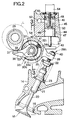
- Fig. 2 is an enlarged view of the essential portion shown in Fig. 1.
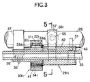
- Fig. 3 is a sectional view taken along a line 3-3 in Fig. 2.
- Fig. 4 is an exploded perspective view of an intake valve operating device.
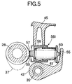
- Fig. 5 is a sectional view taken along a line 5-5 in Fig. 3.
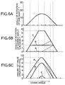
- Figs. 6A, 6B and 6C are diagrams each illustrating a variation in the valve-operational characteristic by definition of rotational angle of carrier.
- Fig. 7 is an exploded perspective view similar to Fig. 4, but according to a second embodiment of the present invention.
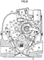
- Fig. 8 is a vertical sectional view of an essential portion of an internal combustion engine.
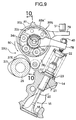
- Fig. 9 is an enlarged view of the essential portion shown in Fig. 8.
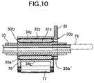
- Fig. 10 is a sectional view taken along a line 10-10 in Fig. 9.
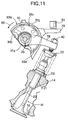
- Fig. 11 is a sectional view similar to Fig. 9, but taken when an engine valve is opened.
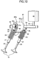
- Fig. 12 is a perspective view of an intake valve operating device.
- Fig. 13 is a vertical sectional view similar to Fig. 8, but according to a fourth embodiment of the present invention.
- Fig. 14 is a vertical sectional view similar to Fig. 8, but according to a fifth embodiment of the present invention.
- Fig. 15 is a perspective view similar to Fig. 12, but according to a sixth embodiment of the present invention.
- a piston 13 is slidably received in a cylinder 12 provided in a cylinder block 11, and a combustion chamber 15 is defined between an upper surface of the piston 13 and a cylinder head 14.
- a pair of intake valve bores 16 and a pair of exhaust valve bores 17 are provided in the cylinder head 14, so that they open into an upper surface of the combustion chamber 15.
- the intake valve bores 16 communicate with an intake port 18, and the exhaust valve bores 17 communicate with an exhaust port 19.
- a pair of intake valves VI capable of individually opening and closing the intake valve bores 16, have stems 20 slidably fitted into guide tubes 21 provided in the cylinder head 14.
- Coiled valve springs 23 are mounted between retainers 22 at upper ends of the stems 20 which protrude upwards from the guide tubes 21 and the cylinder head 14, to surround the stems 20, so that the intake valves VI are biased by the valve springs 23 in a direction to close the intake valve bores 16.
- a pair of exhaust valves VE capable of individually opening and closing the exhaust valve bores 17, are slidably fitted into guide tubes 25 provided in the cylinder head 14.
- Coiled valve springs 27 are mounted between retainers 26 at upper ends of the stems 24 which protrude upwards from the guide tubes 25 and the cylinder head 14, to surround the stems 24, so that the exhaust valves VE are biased by the valve springs 27 in a direction to close the exhaust valve bores 17.
- a cam shaft 28 parallel to an axis of a crankshaft (not shown) is rotatably disposed between the intake valves VI and the exhaust valves VE and is operatively connected to the crankshaft at a reduction ratio of 1/2.
- An intake valve operating device 29I 1 is mounted between the intake valves VI and the cam shaft 28 for converting the rotating movement of the cam shaft 28 into an opening/closing operation of the intake valves VI.
- An exhaust-side valve operating device 29E 1 is mounted between the exhaust valves VE and the cam shaft 28 for converting the rotating movement of the cam shaft 28 into an opening/closing movement of the exhaust valves VE.
- the intake valve operating device 29I 1 includes a power transmitting means 30I 1 which is formed into a planetary gear type by a sun gear 31 1 which is an inner wheel rotatable about an axis, a ring gear 32 1 which is an outer wheel surrounding the sun gear 31 1 for rotation about the same axis as that of the sun gear 31 1 , and a carrier 33 1 which carries a plurality of planetary gears 34 1 which are planetary rotors for rotation about an axis parallel to axes of the sun gear 31 1 and the ring gear 32 1 , and which are rotated in operative association with the rotation of the planetary gears 34 1 about the sun gear 31 1 .
- the power transmitting means 30I 1 is mounted between the cam shaft 28 and the intake valves VI in such a manner that the ring gear 32 1 is disposed between the intake valves VI in a direction parallel to the axis of the cam shaft 28, as viewed from a direction perpendicular to the axis of the cam shaft 28.
- the sun gear 31 1 , the ring gear 32 1 and the carrier 33 1 are three components forming the power transmitting means 30I 1 .
- the sun gear 31 1 is rotatably carried on a support shaft 35 which is fixedly disposed between the cam shaft 28 and the intake valves VI and has an axis parallel to the cam shaft 28.
- An arm 36 integrally connected to one side of the sun gear 31 1 and extending toward the cam shaft 28 is disposed on one side of the ring gear 32 1 , and provided at its tip end with a cam slipper 38 which is in contact with a valve operating cam 37 provided on the cam shaft 28.
- the sun gear 31 1 is operatively connected to the cam shaft 28 and driven in rotation by the valve operating cam 37 in response to the rotation of the cam shaft 28.
- the ring gear 32 1 which is one of the components of the power transmitting means 30I 1 is integrally provided with a connecting arm 39 which is bifurcated and extends toward the intake valves VI.
- a pair of tappet screws 40 are connected to the upper ends of the stems 20 of the intake valves VI, respectively and are threadedly engaged with tip ends of the connecting arm 39 for advancing and retreating movements.
- the ring gear 32 1 is operatively connected to the intake valves VI, so that the intake valves VI are opened and closed in response to the turning of the ring gear 32 1 .
- cam shaft 28 is disposed in such a manner that the projection of the rotational locus L described by the outermost end of the valve operating cam 37 on the cam shaft 28 intersects an outer peripheral surface of the ring gear 32 1 as viewed from an axial direction of the cam shaft 28.
- the carrier 33 1 which is the third component of the power transmitting means 30I 1 is cylindrical in shape having inward-turned collars 33a at opposite ends thereof, and is coaxially inserted between the sun gear 31 1 and ring gear 32 1 .
- the planetary gears 34 1 meshed with an outer periphery of the sun gear 31 1 and an inner periphery of the ring gear 32 1 are rotatably carried on shafts 41 which are disposed at a plurality of points, e.g., three points equally spaced apart from each other in a circumferential direction of the carrier 33 1 and which are mounted between both the inward-turned collars 33a.
- the carrier 33 1 is provided with openings 33b, in which a portion of each of the planetary gears 34 1 faces, so that the planetary gears 34 1 are meshed with the inner periphery of the ring gear 32 1 .
- a cylindrical member 42 rotatably supported by a support shaft 35 is secured at one end thereof to the carrier 33 1 on the opposite side of the sun gear 31 1 from the arm 36, and a control arm 43 having one side facing upwards, is integrally provided at the other end of the cylindrical member 42 on the opposite side from the cam shaft 28.
- a rotational-amount control means 44 is disposed in a head cover 45 at a location above the control arm 43 and in contact with one surface thereof, i.e., an upper surface of the control arm 43.
- the rotational-amount control means 44 includes a piston 47 slidably received in a cylinder bore 46 provided in the head cover 45 to extend vertically, and a lid member 48 which is fixed to the head cover 45 to seal the upper end of the cylinder bore 46 which defines a hydraulic pressure chamber 49 between the lid member 48 and the piston 47.
- a return spring 50 is mounted between the lid member 48 and the piston 47 to exhibit a spring force for biasing the piston 47 downwards.
- a control rod 51 as an operating member coaxially provided at a lower end of the piston 47, contacts an upper surface of the control arm 43.
- An oil passage 52 is provided in the head cover 45 to lead to the hydraulic pressure chamber 49 and is connected to a hydraulic pressure source through a control valve which is not shown, so that oil which continuously varies in pressure depending upon the operational state of the engine, can be supplied to the hydraulic pressure chamber 49.
- the sun gear 31 1 is rotated in a direction shown by an arrow 53 in Fig. 2 by the valve operating cam 37 pushing on arm 36.
- a relatively large spring load for example, of about 20 kgf, is applied to the intake valves VI and the ring gear 32 1 by the valve springs 23 and hence, when the rotation of the carrier 33 1 about the sun gear 31 1 is not controlled by the rotational-amount control means 44, the carrier 33 1 is freely rotated in a direction 54 opposite from the arrow 53 (see Fig. 2), and the intake valves VI cannot be opened and closed.
- each of the planetary gears 34 1 is rotated about its axis by an amount corresponding to a controlled rotational amount to cause the rotation of the ring gear 32 1 , thereby opening the intake valves VI.
- the maximum lift amount and the opening timing i.e., the operational characteristic of the intake valves VI can be changed continuously by continuously changing the controlled rotational amount of the carrier 33 1 .
- the rotational-amount control means 44 continuously controls the rotational amount of the carrier 33 1 about the sun gear 31 1 .
- the spring forces of the valve springs 23 for basing the intake valves VI in closing directions are applied to the carrier 33 1 through the planetary gears 34 1 to bias the control arm 43 upwards
- a force for urging the control arm 43 downwards can be continuously changed.
- the spring forces of the valve springs 23 are increased in accordance with the operation of the intake valves VI in opening directions, and the force for urging the control arm 43 upwards is also increased in accordance with the opening operation of the intake valves VI in opening directions.
- the changing of the force exhibited by the rotational-amount control means 44 ensures that when the intake valves VI are opened to a certain opening degree, the forces applied to the control arm 43 from above and below are balanced with each other.
- the rotational amount of the carrier 33 1 is controlled to such position, and the maximum lift position of the intake valves VI is controlled to the position in which the forces have been balanced with each other, as described above.
- an auxiliary control arm 55 is integrally provided on an intermediate portion of the cylindrical member 42 connected to the carrier 33 1 in such a manner that it is opposed sideways to the cam shaft 28 on the opposite side of the cylindrical member 42 from the cam shaft 28.
- An auxiliary-force applying means 56I is connected to the auxiliary control arm 55.
- an auxiliary cam 57 is fixedly provided on the cam shaft 28 at a location corresponding to the auxiliary control arm 55, and the auxiliary-force applying means 56I is disposed between the auxiliary cam 57 and the auxiliary control arm 55.
- the auxiliary-force applying means 56I includes a support tube 58 fixedly supported on the head cover 45 above the cylindrical member 42 and having an axis perpendicular to the axis of the cam shaft 28.
- a first bottomed cylindrical piston 59 is slidably received in the support tube 58 with its closed end being in sliding contact with the auxiliary cam 57, and a second piston 60 is relatively slidably fitted in the first piston 59 with its closed end being in sliding contact with the auxiliary control arm 55.
- a coiled spring 61 which is mounted between the first and second pistons 59 and 60, exhibits a spring force in a direction to move the pistons 59 and 60 away from each other.
- auxiliary-force applying means 56I With such auxiliary-force applying means 56I, the spring 61 is compressed by the urging of the first piston 59 which is controlled by the auxiliary cam 57, and the spring force of the compressed spring 61 is applied to the auxiliary control arm 55 and thus to the carrier 33 1 through the second piston 60 in the same direction as the control force from the rotational-amount control means 44.
- auxiliary-force applying means 56I a portion of the force opposing the spring forces of the valve springs 23 can be born by the auxiliary-force applying means 56I.
- auxiliary force of the auxiliary-force applying means 56I is synchronized with the time of opening of the intake valves VI.
- the auxiliary cam 57 is fixedly provided on the cam shaft 28 at a location displaced from the valve operating cam 47, for example, through 90° in the circumferential direction of the cam shaft 28, so that the urging force is exerted from the auxiliary cam 57 to the first piston 59, when the a rotating power is transmitted from the valve operating cam 37 to the sun gear 31 1 .
- the control rod 51 is axially operated to a position in which the force exhibited by the rotational-amount control means 44 is balanced with the force of the control arm 43 pushed up by the spring forces of the valve springs 23. If the amount of operation or movement of the control rod 51 is detected, the state in which the forces are balanced with each other, i.e., the maximum lift positions of the intake valves VI can be detected. Therefore, a lift sensor 64 which functions as a detecting means, is mounted on the lid member 48 in the rotational-amount control means 44, and a detecting rod 65 is integrally provided at an upper end of the piston 47 in the rotational-amount control means 44, and is coaxial with the piston 47.
- the detecting rod 65 is oil-tightly and movably passed through the lid member 48 to protrude into the lift sensor 64.
- the lift sensor 64 detects the amount of operation or movement of the detecting rod 65 integrally connected to the control rod 51 through the piston 47, and directly detects the amount of operation of the control rod 51.
- the exhaust-side valve operating device 29E 1 is constructed in the same manner as the intake-side valve operating device 29I 1 and includes a rotational-amount control means (not shown), an auxiliary-force applying means 56E and the like.
- the operation of the first embodiment will be described below with reference to the intake-side valve operating device 29I 1 taken as an example.
- the sun gear 31 1 is driven by the valve operating cam 37 on the cam shaft 28; the ring gear 32 1 is operatively connected to the intake valves VI; and the carrier 33 1 rotated about the sun gear, is continuously controlled by the rotational-amount control means 44. Therefore, the operational characteristic of the intake valves VI can be continuously changed.
- the intake valves VI are opened and closed so that the lift amount and opening time assume maximum values, as shown by a character A in Fig. 6C.
- the intake valves VI are opened and closed, so that the lift amount and opening time shown by character B are smaller than those of the operational characteristic shown by the character A.
- the intake valves VI are opened and closed so that the lift amount and opening time are even smaller than those of the operational characteristic shown by the character B as shown by a character C in Fig. 6C.
- the control of the rotation by the rotational-amount control means 44 may be cancelled as shown by the dashed line in Fig. 6B in the middle of the opening and closing of the intake valves VI. If this is done, the time of the closing of the intake valves VI is hastened as shown by the dashed line in Fig. 6C.
- the power transmitting means 30I 1 is constructed so that the three components forming it, i.e., the sun gear 31 1 , the ring gear 32 1 and the carrier 33 1 are disposed for rotation about the same axis. Therefore, it is possible to provide a compactness of the power transmitting means 30I 1 and to reduce the size of the valve operating device 29I 1 . Moreover, because the power transmitting means 30I 1 is of the planetary gear type, it is possible to accurately control the operational characteristic of the intake valves VI by the meshing connection of the components 31 1 , 32 1 and 33 1 comprising the power transmitting means 30I 1 .
- the cam shaft 28 can be located in proximity to the power transmitting means 30I 1 , while avoiding interference between the valve operating cam 37 and the ring gear 32 1 .
- the degree of freedom for disposition of the cam shaft 28 can be increased.
- the cam shaft 28 is disposed so that the projection of the rotational locus L of the outermost end of the valve operating cam 37 intersects the outer peripheral surface of the ring gear 32 1 as viewed from the axial direction of the cam shaft 28, the cam shaft 28 can be disposed in proximity to the axis of the power transmitting means 30I 1 , thereby providing further compactness to the valve operating device 29I 1 .
- the rotational-amount control means 44 is adapted to apply, to the carrier 33 1 , the control force opposing the spring forces of the valve springs 23 which bias the intake valves VI in the closing direction and which are increased in accordance with the opening operation of the intake valves VI, in such a manner that the control force can be continuously changed.
- the amount of rotation of the carrier 33 1 about the sun gear can be continuously controlled by the continuous changing of the control force. Therefore, a hydraulic actuator adapted to change the force exhibited by the control of the hydraulic pressure, can be used as the rotational-amount control means 44 and thus, the rotational-amount control means 44 can be easily constructed.
- auxiliary-force applying means 56I is connected to the carrier 33 1 , and the force exhibited by the rotational-amount control means 44 can be set at a relatively small value because a portion of the force opposing the spring forces of the valve springs 23 is provided by the auxiliary-force applying means 56I. Thus, it is possible to provide a reduction in size of the rotational-amount control means 44.
- the lift sensor 64 is mounted on the rotational-amount control means 44, so that the amount of operation of the control rod 51, i.e., the control amount of rotation of the carrier 33 1 and the maximum lift amount of the intake valves VI can be detected by the lift sensor 64. Therefore, the operational characteristic of the intake valves VI can be controlled continuously and with high accuracy in correspondence to the operational state of the engine by a feedback control using the detected value detected by the lift sensor 64.
- Fig. 7 illustrates a second embodiment of the present invention, wherein components or portions corresponding to those in the first embodiment are designated by like reference characters.
- a ring gear 32 1 in a power transmitting means 30I 1 is integrally provided with a connecting arm 39' extending toward one of a pair of intake valves VI.
- a tappet screw 40 connected to an upper end of a stem 20 of the one intake valve VI is threadedly engaged with a tip end of the connecting arm 39' for advancing and retreating movements.
- Another tappet screw 40 is threadedly engaged for advancing and retreating movements with a rocker arm 66 which is swingably carried on a support shaft 35.
- the tappet screw 40 is connected to an upper end of a stem 20 of the other intake valve VI.
- the rocker arm 66 is in sliding contact with a valve operating cam which is different from the valve operating cam 37 (see Fig. 2) adapted to apply a power to a power transmitting means 30I 1 .
- the operational characteristic of one of the intake valves VI can be continuously changed, but the other intake valve VI is opened and closed with a fixed operational characteristic.
- the cylindrical member 42 and a rotational-amount control means 44 may be disposed commonly for two adjacent cylinders in a multi-cylinder internal combustion engine. Specifically, in the two adjacent cylinders, the timing of opening of engine valves are displaced along the crank angle and hence, the control force may be exhibited by the rotational-amount control means 44 in correspondence to the timing of opening of the engine valves, respectively. This makes it possible to provide a decrease in number of parts.
- Figs. 8 to 12 illustrate a third embodiment of the present invention, wherein components or portions corresponding to those in each of the above-described embodiments are designated by like reference characters.
- a cam shaft 28 is rotatably disposed between a pair of intake valves VI and a pair of exhaust valves VE in such a manner that it is located below upper ends of the intake valve VI and upper ends of the exhaust valves VE.
- An oil bath 70 is defined in an upper surface of a cylinder head 14, and the cam shaft 28 is disposed at a location in which an intake-side valve operating cam 37I and an exhaust-side valve operating cam 37E provided on the cam shaft 28 can be immersed in an oil within the oil bath 70.
- An intake-side valve operating device 29I 2 is mounted between !he intake valves VI and the intake-side valve operating cam 37I of the cam shaft 28 and capable of converting the rotational movement of the cam shaft 28 into opening and closing movements of the intake valves VI.
- An exhaust-side valve operating device 29E 2 is mounted between the exhaust valves VE and the exhaust-side valve operating cam 37E of the cam shaft 28 and capable of converting the rotational movement of the cam shaft 28 into opening and closing movements of the exhaust valves VE.
- the exhaust-side valve operating device 29E 2 includes a rocker arm shaft 72 fixedly disposed and having an axis parallel to the cam shaft 28, and a rocker arm 73 rotatably carried on the rocker arm shaft 72 and provided between the exhaust valves VE and the exhaust-side valve operating cam 37E.
- a cam slipper 74 is provided at one end of the rocker arm 73 to come into contact with the exhaust-side valve operating cam 37E.
- a pair of tappet screws 75 in contact with upper ends of the exhaust valves VE, are threadedly inserted into the other ends of the rocker arm 73, so that their advanced and retreated positions can be regulated.
- the intake-side valve operating device 29I 2 includes a power transmitting means 30I 2 which is formed into a planetary gear type by a sun gear 31 2 which is an inner wheel rotatable about an axis, a ring gear 32 2 which is an outer wheel surrounding the sun gear 31 2 for rotation about the same axis as the sun gear 31 2 , and a carrier 33 2 on which a plurality of planetary gears 34 2 as planetary rotors are carried for rotation about an axis parallel to axes of the sun gear 31 2 and the ring gear 32 2 which is rotated in operative association with the rotation of the planetary gears 34 2 about the sun gear 31 2 .
- the sun gear 31 2 is rotatably carried on a support shaft 35 fixedly disposed between the cam shaft 28 and the intake valves VI and haying an axis parallel to the axis of the cam shaft 28.
- An arm 76 extending toward the cam shaft 28 is integrally provided on the ring gear 32 2 .
- a roller 77 is rotatably supported at the tip end of the arm 76 and is in contact with the intake-side valve operating cam 37I on the cam shaft 28.
- the ring gear 32 2 is operatively connected to the intake-side valve operating cam 37I on the cam shaft 28 and driven by the intake-side valve operating cam 37I in response to the rotation of the cam shaft 28.
- the point of operative connection of the ring gear 32 2 to the intake-side valve operating cam 37 i.e., the point of contact of the roller 77 with the intake-side valve operating cam 37I is disposed at a location in proximity to the oil bath 70 between the intake valves VI and the cam shaft 28.
- Connecting arms 78 extend toward the intake valves VI on opposite sides of the ring gear 32 2 and are secured to the sun gear 31 2 which is another one of the components of the power transmitting means 30I 2 .
- Tappet screws 40 in contact with upper ends of stems 20 of the intake valves VI, are threadedly inserted into tip ends of the connecting arms 78, respectively for advancing and retreating movements.
- the sun gear 31 2 is operatively connected to the intake valves VI, so that the intake valves VI are opened and closed in response to the rotation of the sun gear 31 2 .
- the carrier 33 2 which is the remainder of the three components of the power transmitting means 30I 2 is coaxially inserted between the sun gear 31 2 and the ring gear 32 2 and includes support plates 33a' at opposite ends thereof.
- the planetary gears 34 2 meshed with an outer periphery of the sun gear 31 2 and an inner periphery of the ring gear 32 2 , are disposed at a plurality of, e.g., six points equally spaced apart from one another in a circumferential direction of the carrier 33 2 , and each rotatably supported at opposite ends thereof by the support plates 33a'.
- One of the support plates 33a' provided on the carrier 33 2 is integrally provided with a control arm 79 extending on the opposite side from the cam shaft 28.
- a rotational-amount control means 44 is disposed in the head cover 45 at a location above the control arm 79 and includes a control rod 51 which is in contact with an upper surface of the control arm 79.
- the ring gear 32 2 is rotated in a direction indicated by an arrow 80 in Figs. 8, 9 and 11 by pushing of the arm 76 by the intake-side valve operating cam 37I.
- a relatively large spring load for example, of about 20 kgf is applied to the intake valves VI and the sun gear 31 2 by the valve springs 23 and hence, when the rotation of the carrier 33 2 about the sun gear 31 2 is not controlled, the carrier 33 2 is freely rotated in the same direction as the arrow 80, and the intake valves VI cannot be opened and closed.
- each of the planetary gears 34 2 is rotated about its axis by an amount corresponding to a controlled rotational amount to cause the rotation of the ring gear 32 2 , thereby opening the intake valves VI.
- the maximum lift amount and the opening timing i.e., the operational characteristic of the intake valves VI can be changed continuously by continuously changing the controlled rotational amount of the carrier 33 2 .
- the rotational-amount control means 44 continuously controls the rotational amount of the carrier 33 2 about the sun gear 31 2 .
- the spring forces of the valve springs 23 for biasing the intake valves VI in closing directions are applied to the carrier 33 2 through the sun gear 31 2 and the planetary gears 34 2 to bias the control arm 79 upwards
- a force for urging the control arm 79 downwards can be continuously changed.
- the spring force of the valve springs 23 are increased in accordance with the operation of the intake valves VI in the opening direction of the intake valves VI, and the force for urging the control arm 79 upwards is also increased in accordance with the opening operation of the intake valves VI.
- the changing of the force exhibited by the rotational-amount control means 44 ensures that when the intake valves VI are opened to a certain opening degree, the forces applied to the control arm 79 from above and below are balanced with each other.
- the rotational amount of the carrier 33 2 is controlled to such position, and the maximum lift position of the intake valves VI is controlled to the position in which the forces have been balanced with each other, as described above.
- an upward extending auxiliary control arm 81 is integrally provided on the one support plate 33a' on the carrier 33 2 , and an auxiliary-force applying means 56' is operatively connected to the auxiliary control arm 81.
- the auxiliary-force applying means 56' includes a support tube 82 fixedly supported on the head cover 45, a piston 83 slidably received in the support tube 82 with its one end being in contact with the auxiliary control arm 81, and a spring 84 which is mounted between the support tube 82 and piston 83.
- the spring 84 exhibits a spring force in a direction to urge the piston 83 against the auxiliary control arm 81.
- auxiliary-force applying means 56' With such auxiliary-force applying means 56', the spring force exhibited by the spring 84 can be applied to the auxiliary control arm 81 and thus to the carrier 33 2 in the same direction as the control force from the rotational-amount control means 44, so that a portion of the force opposing the spring forces of the valve springs 23 can be provided by the auxiliary-force applying means 56'.
- the operation of the third embodiment will be described below.
- the three components forming the power transmitting means 30I 2 of the planetary gear type in the intake-side valve operating device 29I 2 are the sun gear 31 2 , the ring gear 32 2 and the carrier 33 2 , the ring gear 32 2 and the sun gear 31 2 are operatively connected to the intake-side valve operating cam 37I on the cam shaft 28 and the intake valves VI, respectively, and the amount of carrier 33 2 rotated about the sun gear is continuously controlled by the rotational-amount control means 44. Therefore, the operational characteristic of the intake valves VI can be continuously and finely controlled.
- the power transmitting means 30I 2 is of the planetary gear type in which the three components comprising the power transmitting means 30I 2 , i.e., the sun gear 31 2 , the ring gear 32 2 and the carrier 33 2 are disposed for rotation about the same axis. Therefore, it is possible to provide a compact power transmitting means 30I 2 and reduce the size of the valve operating device 29I 2 , and it is possible to accurately control the operational characteristic of the intake valves VI by the meshing connection of the components 31 2 , 32 2 and 33 2 forming the power transmitting means 30I 2 .
- the amount of rotation of the ring gear 32 2 is smaller than that of the sun gear 31 2 , and the ring gear 32 2 is operatively connected to the intake-side valve operating cam 37I on the cam shaft 28, while the sun gear 31 2 is operatively connected to the intake valves VI. Therefore, the lift amount required for the intake valves VI, i.e., the size of the intake-side valve operating cam 37I suitable for the amount of rotation of the sun gear 31 2 can be set at a relatively small value. Thus, the load received from the intake-side valve operating cam 37I by the ring gear 32 2 can be relatively decreased to contribute to the alleviation of the valve operating load.
- the roller 77 supported on the arm 76 of the ring gear 32 2 is in rolling contact with the intake-side valve operating cam 37I and hence, the valve operating load can be further decreased. Further, because of the relatively small intake-side valve operating cam 37I, the space required for rotation of the intake-side valve operating cam 37I as well as the space required for operation of the arm 76 of the ring gear 32 2 can be also reduced, thereby providing a compact valve operating chamber for the disposition of the intake-side valve operating device 29I 2 .
- the single ring gear 32 2 is disposed between a pair of intake valves VI adjacent each other in the direction parallel to the axis of the cam shaft 28, and the intake valves VI are operatively connected to the sun gear 31 2 on the axially opposite sides of the ring gear 32 2 , the pair of intake valves VI, whose operational characteristic can be changed, can be opened and closed by the power transmitting means 30I 2 disposed compactly between the intake valves VI, and the intake-side valve operating device 29I 2 can be made compact.
- the cam shaft 28 is disposed at the location between the intake valves VI and the exhaust valves VE and below the upper ends of the intake valves VI and the exhaust valves VE, and the point of operative connection of the intake-side valve operating cam 37I with the ring gear 32 2 is disposed between the intake valves VI and the cam shaft 28, the power transmitting means 30I 2 can be disposed in proximity to the upper surface of the cylinder head 14, thereby providing compactness of the valve operating chamber.
- the intake-side and exhaust-side valve operating cams 37I and 37E are immersed in the oil within the oil bath defined in the upper surface of the cylinder head 14, the lubrication of the power transmitting means 30I 2 can be satisfactorily performed by raking up the oil with the intake-side and exhaust-side valve operating cams 37I and 37E.
- the oil raked up by the intake-side and exhaust-side valve operating cams 37I and 37E can be effectively scattered toward the power transmitting means 30I 2 to more effectively perform the lubrication of the power transmitting means 30I 2 by the fact that the cam shaft 28 is rotated in a counterclockwise direction as viewed in Fig. 8.
- the lubrication of the roller 77 can be also satisfactorily performed because the point of operative connection of the intake-side valve operating cam 37I and the ring gear 32 2 , i.e., the point of contact of the roller 77 with the intake-side valve operating cam 37I is in proximity to the oil bath 70.
- Fig. 13 illustrates a fourth embodiment of the present invention.
- a cam shaft 28 is disposed above the upper ends of the intake valves VI and the exhaust valves VE, and the auxiliary-force applying means 56' is omitted.
- FIG. 14 illustrates a fifth embodiment of the present invention.
- a power transmitting means 30I 2 is disposed in such a manner that a projection of a portion of the ring gear 32 2 is superposed on a portion of a coiled valve spring 23 surrounding an upper portion of each of the intake valves VI, as viewed in the axial direction of the ring gear 32 2 .
- the power transmitting means 30I 2 can be disposed in closer proximity to the intake valves VI, whereby the valve operating chamber can be made compact.
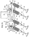
- FIG. 15 illustrates a sixth embodiment of the present invention.
- a rotational-amount control means 44 may be disposed commonly for two adjacent cylinders whose opening periods are not overlapped with each other in a multi-cylinder internal combustion engine. Specifically, in the two adjacent cylinders whose opening periods are not overlapped with each other, the control force may be exhibited synchronously with the opening timing of each of the cylinders by the rotational-amount control means 44. Thus, it is possible to provide a decrease in the number of parts.
- control arms 79 in the power transmitting means 30I 2 for the two adjacent cylinders may be superposed on each other, and the control rod 51 of the rotational-amount control means 44 may be disposed to come into contact with the superposed portions of the control arms 79.
- the control arms 79 of the power transmitting means 30I 2 for the two adjacent cylinders may be formed integrally with each other.
- any of a linear solenoid, a step motor and the like may be used as the rotational-amount control means.
- a step motor one of the three components of the power transmitting means, whose rotational amount is controlled by the step motor, can be mechanically locked and hence, it is possible to enhance the accuracy of control of the valve operational characteristics and to reduce the size of the valve operating device.
- Planetary friction-type power transmitting means as disclosed in Japanese Patent Application Laid-open Nos. 5-33840, 5-79450, 5-157149, 6-34005 and 6-66360 may be used as the power transmitting means.
- the rotational amount of one of the three components comprising the power transmitting means, which is operatively connected to the rotational-amount control means, can be controlled at a plurality of stages rather than continuously, and in this case, the operational characteristics of the engine valves can be finely controlled by setting the number of stages to a larger value.
- a valve operating system in an internal combustion engine wherein the operational characteristic of an engine valve which is an intake valve or an exhaust valve, can be changed in accordance with the operational state of the engine.
- a power transmitting means comprises an inner wheel, an outer wheel surrounding the inner wheel, and a carrier on which a planetary rotor is rotatably carried.
- the inner wheel is operatively connected to a cam shaft, and the outer wheel is connected to the engine valve.
- a rotational-amount control device is connected to the carrier for controlling the rotational amount of the carrier in accordance with the operational state of the engine.
Landscapes
- Engineering & Computer Science (AREA)
- Mechanical Engineering (AREA)
- General Engineering & Computer Science (AREA)
- Valve Device For Special Equipments (AREA)
- Valve-Gear Or Valve Arrangements (AREA)
- Output Control And Ontrol Of Special Type Engine (AREA)
Applications Claiming Priority (6)
| Application Number | Priority Date | Filing Date | Title |
|---|---|---|---|
| JP23228396 | 1996-09-02 | ||
| JP23228396 | 1996-09-02 | ||
| JP232283/96 | 1996-09-02 | ||
| JP138336/97 | 1997-05-28 | ||
| JP13833697 | 1997-05-28 | ||
| JP13833697 | 1997-05-28 |
Publications (3)
| Publication Number | Publication Date |
|---|---|
| EP0826866A2 true EP0826866A2 (fr) | 1998-03-04 |
| EP0826866A3 EP0826866A3 (fr) | 1998-04-08 |
| EP0826866B1 EP0826866B1 (fr) | 2002-12-11 |
Family
ID=26471395
Family Applications (1)
| Application Number | Title | Priority Date | Filing Date |
|---|---|---|---|
| EP97115201A Expired - Lifetime EP0826866B1 (fr) | 1996-09-02 | 1997-09-02 | Commande de soupape d'un moteur à combustion interne |
Country Status (10)
| Country | Link |
|---|---|
| US (1) | US6016779A (fr) |
| EP (1) | EP0826866B1 (fr) |
| KR (1) | KR100317151B1 (fr) |
| CN (1) | CN1088792C (fr) |
| AU (1) | AU700821B2 (fr) |
| CA (1) | CA2214301C (fr) |
| DE (1) | DE69717740T2 (fr) |
| ES (1) | ES2188832T3 (fr) |
| MY (1) | MY129629A (fr) |
| TW (1) | TW390934B (fr) |
Cited By (5)
| Publication number | Priority date | Publication date | Assignee | Title |
|---|---|---|---|---|
| EP0913557A3 (fr) * | 1997-10-29 | 2000-05-03 | Honda Giken Kogyo Kabushiki Kaisha | Dispositif de commande de soupape dans un moteur à combustion interne |
| EP1143119B1 (fr) * | 2000-03-21 | 2005-01-12 | Toyota Jidosha Kabushiki Kaisha | Dispositif pour varier la phase et la course d'une soupape et appareil de contrôle de volume d'air d'admission |
| EP1921282A3 (fr) * | 2006-10-31 | 2010-08-11 | Mitsubishi Jidosha Kogyo Kabushiki Kaisha | Structure d'agencement d'un actionneur à commande électrique |
| WO2012126648A1 (fr) * | 2011-03-22 | 2012-09-27 | Kolbenschmidt Pierburg Innovations Gmbh | Entraînement de soupapes à commande mécanique et système d'entraînement de soupapes à commande mécanique |
| EP3244031A1 (fr) * | 2016-04-13 | 2017-11-15 | MAN Truck & Bus AG | Commande de soupape variable comprenant un culbuteur |
Families Citing this family (11)
| Publication number | Priority date | Publication date | Assignee | Title |
|---|---|---|---|---|
| GB2348246B (en) * | 1999-03-25 | 2002-11-13 | Ricardo Inc | Automotive valve rocker arms |
| US6623510B2 (en) * | 2000-12-07 | 2003-09-23 | Integrated Vascular Systems, Inc. | Closure device and methods for making and using them |
| JP3938339B2 (ja) * | 2001-07-26 | 2007-06-27 | 本田技研工業株式会社 | 内燃機関の動弁制御装置 |
| JP4026410B2 (ja) * | 2002-05-24 | 2007-12-26 | 三菱自動車工業株式会社 | 内燃機関の動弁装置 |
| DE10306907B4 (de) * | 2003-02-17 | 2004-12-09 | Iav Gmbh Ingenieurgesellschaft Auto Und Verkehr | Ventiltrieb mit variabel einstellbarem Hub für Ventile von Verbrennungsmotoren |
| JP4221327B2 (ja) * | 2004-04-13 | 2009-02-12 | 三菱ふそうトラック・バス株式会社 | 内燃機関の可変動弁装置 |
| DE102004037198A1 (de) * | 2004-07-30 | 2006-03-23 | Ina-Schaeffler Kg | Ventiltrieb einer Brennkraftmaschine |
| CN102102552A (zh) * | 2011-03-28 | 2011-06-22 | 南京金城机械有限公司 | 一种凸轮偏置式配气机构 |
| CN104819022B (zh) * | 2015-03-23 | 2023-09-05 | 上海尤顺汽车技术有限公司 | 一种发动机冷启动机构 |
| CN109184842B (zh) * | 2018-10-12 | 2023-08-08 | 福泰动力有限公司 | 气门驱动装置和气门驱动系统 |
| CN112483210B (zh) * | 2019-09-11 | 2024-09-10 | 舍弗勒投资(中国)有限公司 | 用于操纵能移动的锁定器件的设备 |
Citations (6)
| Publication number | Priority date | Publication date | Assignee | Title |
|---|---|---|---|---|
| JPH0533840A (ja) | 1991-07-29 | 1993-02-09 | Canon Inc | 遊星摩擦式変速装置 |
| JPH0579450A (ja) | 1991-09-20 | 1993-03-30 | Mitsubishi Heavy Ind Ltd | 風 車 |
| JPH05157149A (ja) | 1991-12-02 | 1993-06-22 | Shimpo Ind Co Ltd | 遊星型摩擦伝動増減速機 |
| JPH0634005A (ja) | 1992-07-13 | 1994-02-08 | Koyo Seiko Co Ltd | 遊星ローラ式動力伝達装置 |
| JPH0666360A (ja) | 1992-08-20 | 1994-03-08 | Mitsubishi Heavy Ind Ltd | 風車発電機用トラクションドライブ増速機 |
| JPH07107368A (ja) | 1993-09-29 | 1995-04-21 | Canon Inc | 画像処理装置 |
Family Cites Families (10)
| Publication number | Priority date | Publication date | Assignee | Title |
|---|---|---|---|---|
| IT1145440B (it) * | 1979-07-31 | 1986-11-05 | Daimler Benz Ag | Motore a combustione interna a piu' cilindri con sistema di disinnesto delle valvole |
| FR2519375B1 (fr) * | 1981-12-31 | 1986-07-11 | Baguena Michel | Distribution variable pour moteur a quatre temps |
| JPS6011612A (ja) * | 1983-06-29 | 1985-01-21 | Atsugi Motor Parts Co Ltd | 内燃機関における気筒数可変機構 |
| JP2700692B2 (ja) * | 1989-06-30 | 1998-01-21 | スズキ株式会社 | 4サイクルエンジンの動弁装置 |
| US5003939A (en) * | 1990-02-26 | 1991-04-02 | King Brian T | Valve duration and lift variator for internal combustion engines |
| US5148783A (en) * | 1990-03-08 | 1992-09-22 | Suzuki Kabushiki Kaisha | Valve actuating mechanism in four-stroke cycle engine |
| US5025761A (en) * | 1990-06-13 | 1991-06-25 | Chen Kuang Tong | Variable valve-timing device |
| JPH04241709A (ja) * | 1991-01-11 | 1992-08-28 | Toyota Motor Corp | 軸間位相変換装置 |
| US5327859A (en) * | 1993-06-09 | 1994-07-12 | General Motors Corporation | Engine timing drive with fixed and variable phasing |
| KR100203883B1 (ko) * | 1996-08-30 | 1999-06-15 | 정몽규 | 자동차의 가변 타이밍 벨트 시스템 |
-
1997
- 1997-08-29 CA CA002214301A patent/CA2214301C/fr not_active Expired - Fee Related
- 1997-08-29 US US08/921,255 patent/US6016779A/en not_active Expired - Fee Related
- 1997-08-30 MY MYPI97004033A patent/MY129629A/en unknown
- 1997-09-01 AU AU36120/97A patent/AU700821B2/en not_active Ceased
- 1997-09-01 TW TW086112521A patent/TW390934B/zh active
- 1997-09-02 KR KR1019970045564A patent/KR100317151B1/ko not_active Expired - Fee Related
- 1997-09-02 CN CN97120655A patent/CN1088792C/zh not_active Expired - Fee Related
- 1997-09-02 DE DE69717740T patent/DE69717740T2/de not_active Expired - Fee Related
- 1997-09-02 EP EP97115201A patent/EP0826866B1/fr not_active Expired - Lifetime
- 1997-09-02 ES ES97115201T patent/ES2188832T3/es not_active Expired - Lifetime
Patent Citations (6)
| Publication number | Priority date | Publication date | Assignee | Title |
|---|---|---|---|---|
| JPH0533840A (ja) | 1991-07-29 | 1993-02-09 | Canon Inc | 遊星摩擦式変速装置 |
| JPH0579450A (ja) | 1991-09-20 | 1993-03-30 | Mitsubishi Heavy Ind Ltd | 風 車 |
| JPH05157149A (ja) | 1991-12-02 | 1993-06-22 | Shimpo Ind Co Ltd | 遊星型摩擦伝動増減速機 |
| JPH0634005A (ja) | 1992-07-13 | 1994-02-08 | Koyo Seiko Co Ltd | 遊星ローラ式動力伝達装置 |
| JPH0666360A (ja) | 1992-08-20 | 1994-03-08 | Mitsubishi Heavy Ind Ltd | 風車発電機用トラクションドライブ増速機 |
| JPH07107368A (ja) | 1993-09-29 | 1995-04-21 | Canon Inc | 画像処理装置 |
Cited By (9)
| Publication number | Priority date | Publication date | Assignee | Title |
|---|---|---|---|---|
| EP0913557A3 (fr) * | 1997-10-29 | 2000-05-03 | Honda Giken Kogyo Kabushiki Kaisha | Dispositif de commande de soupape dans un moteur à combustion interne |
| US6138620A (en) * | 1997-10-29 | 2000-10-31 | Honda Giken Kogyo Kabushiki Kaisha | Valve operating system in an internal combustion engine |
| EP1143119B1 (fr) * | 2000-03-21 | 2005-01-12 | Toyota Jidosha Kabushiki Kaisha | Dispositif pour varier la phase et la course d'une soupape et appareil de contrôle de volume d'air d'admission |
| EP1921282A3 (fr) * | 2006-10-31 | 2010-08-11 | Mitsubishi Jidosha Kogyo Kabushiki Kaisha | Structure d'agencement d'un actionneur à commande électrique |
| WO2012126648A1 (fr) * | 2011-03-22 | 2012-09-27 | Kolbenschmidt Pierburg Innovations Gmbh | Entraînement de soupapes à commande mécanique et système d'entraînement de soupapes à commande mécanique |
| CN103429859A (zh) * | 2011-03-22 | 2013-12-04 | 科尔本施密特皮尔伯格创新股份有限公司 | 可机械式控制的气门传动机构以及可机械式控制的气门传动装置 |
| US9133737B2 (en) | 2011-03-22 | 2015-09-15 | Kolbenschmidt Pierburg Innovations Gmbh | Mechanically controllable valve drive and mechanically controllable valve drive arrangement |
| EP3244031A1 (fr) * | 2016-04-13 | 2017-11-15 | MAN Truck & Bus AG | Commande de soupape variable comprenant un culbuteur |
| US10287929B2 (en) | 2016-04-13 | 2019-05-14 | Man Truck & Bus Ag | Variable valve drive having a rocker lever |
Also Published As
| Publication number | Publication date |
|---|---|
| MY129629A (en) | 2007-04-30 |
| ES2188832T3 (es) | 2003-07-01 |
| CN1088792C (zh) | 2002-08-07 |
| TW390934B (en) | 2000-05-21 |
| CN1180784A (zh) | 1998-05-06 |
| KR19980024282A (ko) | 1998-07-06 |
| AU700821B2 (en) | 1999-01-14 |
| KR100317151B1 (ko) | 2002-06-20 |
| EP0826866A3 (fr) | 1998-04-08 |
| AU3612097A (en) | 1998-03-05 |
| CA2214301C (fr) | 2001-04-24 |
| EP0826866B1 (fr) | 2002-12-11 |
| CA2214301A1 (fr) | 1998-03-02 |
| DE69717740D1 (de) | 2003-01-23 |
| US6016779A (en) | 2000-01-25 |
| DE69717740T2 (de) | 2003-08-21 |
Similar Documents
| Publication | Publication Date | Title |
|---|---|---|
| EP0826866B1 (fr) | Commande de soupape d'un moteur à combustion interne | |
| JP2810442B2 (ja) | エンジンの弁作動装置 | |
| US5074260A (en) | Valve driving device and valve driving method for internal combustion engine | |
| US4539951A (en) | Variable valve timing mechanism | |
| US8127739B2 (en) | Variable stroke engine | |
| US5107802A (en) | Valve driving mechanism for internal combustion engines | |
| US5431132A (en) | Variable valve gear of internal combustion engines | |
| US6779495B2 (en) | Variable compression ratio engine | |
| KR20050016757A (ko) | 내연 기관의 밸브 작동 장치 | |
| US7305946B2 (en) | Variable valve operating apparatus for internal combustion engine | |
| EP2048336B1 (fr) | Moteur avec piston de course variable | |
| US6968819B2 (en) | Variable valve actuating device | |
| US5893345A (en) | Valve control apparatus for an internal combustion engine | |
| US6085707A (en) | Valve operating system in internal combustion engine | |
| US7383800B2 (en) | Assembly for actuating apparatus | |
| US5626107A (en) | Valve systems for internal combustion piston engines | |
| JP4090340B2 (ja) | 内燃機関の動弁装置 | |
| US6742483B2 (en) | Assisting device and method for variable valve mechanism | |
| JP2592964B2 (ja) | エンジンの動弁装置 | |
| US7581523B2 (en) | Auxiliary arrangement structure in internal combustion engine | |
| JP4179101B2 (ja) | エンジンの可変動弁装置 | |
| JP4090339B2 (ja) | 内燃機関の動弁装置 | |
| JPH10121927A (ja) | 内燃機関の動弁装置 | |
| JPH11264310A (ja) | 内燃機関の動弁装置 | |
| JPH039026A (ja) | 内燃機関の吸排気装置 |
Legal Events
| Date | Code | Title | Description |
|---|---|---|---|
| PUAI | Public reference made under article 153(3) epc to a published international application that has entered the european phase |
Free format text: ORIGINAL CODE: 0009012 |
|
| PUAL | Search report despatched |
Free format text: ORIGINAL CODE: 0009013 |
|
| AK | Designated contracting states |
Kind code of ref document: A2 Designated state(s): DE ES FR GB |
|
| AX | Request for extension of the european patent |
Free format text: AL;LT;LV;RO;SI |
|
| AK | Designated contracting states |
Kind code of ref document: A3 Designated state(s): AT BE CH DE DK ES FI FR GB GR IE IT LI LU MC NL PT SE |
|
| AX | Request for extension of the european patent |
Free format text: AL;LT;LV;RO;SI |
|
| 17P | Request for examination filed |
Effective date: 19981005 |
|
| AKX | Designation fees paid |
Free format text: DE ES FR GB |
|
| RBV | Designated contracting states (corrected) |
Designated state(s): DE ES FR GB |
|
| 17Q | First examination report despatched |
Effective date: 20010717 |
|
| GRAG | Despatch of communication of intention to grant |
Free format text: ORIGINAL CODE: EPIDOS AGRA |
|
| GRAG | Despatch of communication of intention to grant |
Free format text: ORIGINAL CODE: EPIDOS AGRA |
|
| GRAH | Despatch of communication of intention to grant a patent |
Free format text: ORIGINAL CODE: EPIDOS IGRA |
|
| GRAH | Despatch of communication of intention to grant a patent |
Free format text: ORIGINAL CODE: EPIDOS IGRA |
|
| GRAA | (expected) grant |
Free format text: ORIGINAL CODE: 0009210 |
|
| AK | Designated contracting states |
Kind code of ref document: B1 Designated state(s): DE ES FR GB |
|
| REG | Reference to a national code |
Ref country code: GB Ref legal event code: FG4D |
|
| REF | Corresponds to: |
Ref document number: 69717740 Country of ref document: DE Date of ref document: 20030123 |
|
| REG | Reference to a national code |
Ref country code: ES Ref legal event code: FG2A Ref document number: 2188832 Country of ref document: ES Kind code of ref document: T3 |
|
| ET | Fr: translation filed | ||
| PGFP | Annual fee paid to national office [announced via postgrant information from national office to epo] |
Ref country code: GB Payment date: 20030828 Year of fee payment: 7 |
|
| PGFP | Annual fee paid to national office [announced via postgrant information from national office to epo] |
Ref country code: ES Payment date: 20030916 Year of fee payment: 7 |
|
| PGFP | Annual fee paid to national office [announced via postgrant information from national office to epo] |
Ref country code: FR Payment date: 20030925 Year of fee payment: 7 |
|
| PLBE | No opposition filed within time limit |
Free format text: ORIGINAL CODE: 0009261 |
|
| STAA | Information on the status of an ep patent application or granted ep patent |
Free format text: STATUS: NO OPPOSITION FILED WITHIN TIME LIMIT |
|
| 26N | No opposition filed |
Effective date: 20030912 |
|
| PG25 | Lapsed in a contracting state [announced via postgrant information from national office to epo] |
Ref country code: GB Free format text: LAPSE BECAUSE OF NON-PAYMENT OF DUE FEES Effective date: 20040902 |
|
| PGFP | Annual fee paid to national office [announced via postgrant information from national office to epo] |
Ref country code: DE Payment date: 20040902 Year of fee payment: 8 |
|
| PG25 | Lapsed in a contracting state [announced via postgrant information from national office to epo] |
Ref country code: ES Free format text: LAPSE BECAUSE OF NON-PAYMENT OF DUE FEES Effective date: 20040903 |
|
| GBPC | Gb: european patent ceased through non-payment of renewal fee |
Effective date: 20040902 |
|
| PG25 | Lapsed in a contracting state [announced via postgrant information from national office to epo] |
Ref country code: FR Free format text: LAPSE BECAUSE OF NON-PAYMENT OF DUE FEES Effective date: 20050531 |
|
| REG | Reference to a national code |
Ref country code: FR Ref legal event code: ST |
|
| REG | Reference to a national code |
Ref country code: ES Ref legal event code: FD2A Effective date: 20040903 |
|
| PG25 | Lapsed in a contracting state [announced via postgrant information from national office to epo] |
Ref country code: DE Free format text: LAPSE BECAUSE OF NON-PAYMENT OF DUE FEES Effective date: 20060401 |