EP0827029A2 - Composition de polymères à haute performance - Google Patents
Composition de polymères à haute performance Download PDFInfo
- Publication number
- EP0827029A2 EP0827029A2 EP97306200A EP97306200A EP0827029A2 EP 0827029 A2 EP0827029 A2 EP 0827029A2 EP 97306200 A EP97306200 A EP 97306200A EP 97306200 A EP97306200 A EP 97306200A EP 0827029 A2 EP0827029 A2 EP 0827029A2
- Authority
- EP
- European Patent Office
- Prior art keywords
- groups
- polymer
- imparting
- substituent
- heating elements
- Prior art date
- Legal status (The legal status is an assumption and is not a legal conclusion. Google has not performed a legal analysis and makes no representation as to the accuracy of the status listed.)
- Withdrawn
Links
- 0 CC(C)(C)*N(C(C=O)c1cc(Cc(cc2)cc(C(N3C(C)(C)C)=O)c2C3=O)ccc11)C1=O Chemical compound CC(C)(C)*N(C(C=O)c1cc(Cc(cc2)cc(C(N3C(C)(C)C)=O)c2C3=O)ccc11)C1=O 0.000 description 8
- ZTVXQLITVQGJEE-UHFFFAOYSA-N CC(C)c1ccc(C(C)(C)C)c(C(c2ccc(C)cc2)=O)c1 Chemical compound CC(C)c1ccc(C(C)(C)C)c(C(c2ccc(C)cc2)=O)c1 ZTVXQLITVQGJEE-UHFFFAOYSA-N 0.000 description 1
Images


Classifications
-
- B—PERFORMING OPERATIONS; TRANSPORTING
- B41—PRINTING; LINING MACHINES; TYPEWRITERS; STAMPS
- B41J—TYPEWRITERS; SELECTIVE PRINTING MECHANISMS, i.e. MECHANISMS PRINTING OTHERWISE THAN FROM A FORME; CORRECTION OF TYPOGRAPHICAL ERRORS
- B41J2/00—Typewriters or selective printing mechanisms characterised by the printing or marking process for which they are designed
- B41J2/005—Typewriters or selective printing mechanisms characterised by the printing or marking process for which they are designed characterised by bringing liquid or particles selectively into contact with a printing material
- B41J2/01—Ink jet
- B41J2/135—Nozzles
- B41J2/14—Structure thereof only for on-demand ink jet heads
- B41J2/14016—Structure of bubble jet print heads
- B41J2/14032—Structure of the pressure chamber
-
- B—PERFORMING OPERATIONS; TRANSPORTING
- B41—PRINTING; LINING MACHINES; TYPEWRITERS; STAMPS
- B41J—TYPEWRITERS; SELECTIVE PRINTING MECHANISMS, i.e. MECHANISMS PRINTING OTHERWISE THAN FROM A FORME; CORRECTION OF TYPOGRAPHICAL ERRORS
- B41J2/00—Typewriters or selective printing mechanisms characterised by the printing or marking process for which they are designed
- B41J2/005—Typewriters or selective printing mechanisms characterised by the printing or marking process for which they are designed characterised by bringing liquid or particles selectively into contact with a printing material
- B41J2/01—Ink jet
- B41J2/135—Nozzles
- B41J2/14—Structure thereof only for on-demand ink jet heads
- B41J2/14016—Structure of bubble jet print heads
- B41J2/14088—Structure of heating means
- B41J2/14112—Resistive element
- B41J2/14129—Layer structure
-
- G—PHYSICS
- G03—PHOTOGRAPHY; CINEMATOGRAPHY; ANALOGOUS TECHNIQUES USING WAVES OTHER THAN OPTICAL WAVES; ELECTROGRAPHY; HOLOGRAPHY
- G03F—PHOTOMECHANICAL PRODUCTION OF TEXTURED OR PATTERNED SURFACES, e.g. FOR PRINTING, FOR PROCESSING OF SEMICONDUCTOR DEVICES; MATERIALS THEREFOR; ORIGINALS THEREFOR; APPARATUS SPECIALLY ADAPTED THEREFOR
- G03F7/00—Photomechanical, e.g. photolithographic, production of textured or patterned surfaces, e.g. printing surfaces; Materials therefor, e.g. comprising photoresists; Apparatus specially adapted therefor
- G03F7/004—Photosensitive materials
- G03F7/038—Macromolecular compounds which are rendered insoluble or differentially wettable
-
- G—PHYSICS
- G03—PHOTOGRAPHY; CINEMATOGRAPHY; ANALOGOUS TECHNIQUES USING WAVES OTHER THAN OPTICAL WAVES; ELECTROGRAPHY; HOLOGRAPHY
- G03F—PHOTOMECHANICAL PRODUCTION OF TEXTURED OR PATTERNED SURFACES, e.g. FOR PRINTING, FOR PROCESSING OF SEMICONDUCTOR DEVICES; MATERIALS THEREFOR; ORIGINALS THEREFOR; APPARATUS SPECIALLY ADAPTED THEREFOR
- G03F7/00—Photomechanical, e.g. photolithographic, production of textured or patterned surfaces, e.g. printing surfaces; Materials therefor, e.g. comprising photoresists; Apparatus specially adapted therefor
- G03F7/004—Photosensitive materials
- G03F7/038—Macromolecular compounds which are rendered insoluble or differentially wettable
- G03F7/0388—Macromolecular compounds which are rendered insoluble or differentially wettable with ethylenic or acetylenic bands in the side chains of the photopolymer
-
- B—PERFORMING OPERATIONS; TRANSPORTING
- B41—PRINTING; LINING MACHINES; TYPEWRITERS; STAMPS
- B41J—TYPEWRITERS; SELECTIVE PRINTING MECHANISMS, i.e. MECHANISMS PRINTING OTHERWISE THAN FROM A FORME; CORRECTION OF TYPOGRAPHICAL ERRORS
- B41J2202/00—Embodiments of or processes related to ink-jet or thermal heads
- B41J2202/01—Embodiments of or processes related to ink-jet heads
- B41J2202/03—Specific materials used
-
- Y—GENERAL TAGGING OF NEW TECHNOLOGICAL DEVELOPMENTS; GENERAL TAGGING OF CROSS-SECTIONAL TECHNOLOGIES SPANNING OVER SEVERAL SECTIONS OF THE IPC; TECHNICAL SUBJECTS COVERED BY FORMER USPC CROSS-REFERENCE ART COLLECTIONS [XRACs] AND DIGESTS
- Y10—TECHNICAL SUBJECTS COVERED BY FORMER USPC
- Y10S—TECHNICAL SUBJECTS COVERED BY FORMER USPC CROSS-REFERENCE ART COLLECTIONS [XRACs] AND DIGESTS
- Y10S522/00—Synthetic resins or natural rubbers -- part of the class 520 series
- Y10S522/904—Monomer or polymer contains initiating group
-
- Y—GENERAL TAGGING OF NEW TECHNOLOGICAL DEVELOPMENTS; GENERAL TAGGING OF CROSS-SECTIONAL TECHNOLOGIES SPANNING OVER SEVERAL SECTIONS OF THE IPC; TECHNICAL SUBJECTS COVERED BY FORMER USPC CROSS-REFERENCE ART COLLECTIONS [XRACs] AND DIGESTS
- Y10—TECHNICAL SUBJECTS COVERED BY FORMER USPC
- Y10S—TECHNICAL SUBJECTS COVERED BY FORMER USPC CROSS-REFERENCE ART COLLECTIONS [XRACs] AND DIGESTS
- Y10S522/00—Synthetic resins or natural rubbers -- part of the class 520 series
- Y10S522/904—Monomer or polymer contains initiating group
- Y10S522/905—Benzophenone group
Definitions
- the present invention is directed to curable compositions having improved characteristics.
- the present invention is also directed to improved photoresist compositions and to improved thermal ink jet printheads.
- microelectronics applications include printed circuit boards, lithographic printing processes, and interlayer dielectrics.
- Copending application U.S. Serial No. 08/705,375 discloses an improved composition comprising a defined polymer containing at least some monomer repeat units with photosensitivity-imparting substituents.
- Copending application U.S. Serial No08/705,365 discloses a composition which comprises (a) a polymer containing at least some monomer repeat units with photosensitivity-imparting substituents which enable crosslinking or chain extension of the polymer upon exposure to actinic radiation, wherein said photosensitivity-imparting substituents are hydroxyalkyl groups; (b) at least one member selected from the group consisting of photoinitiators and sensitizers; and (c) an optional solvent.
- Copending application U.S. Serial No. 08/697,761 discloses a process which comprises reacting a defined polymer with (i) a formaldehyde source, and (ii) an unsaturated acid in the presence of an acid catalyst, thereby forming a curable polymer with unsaturated ester groups.
- Copending application U.S. Serial No. 08/705,463 discloses a process which comprises reacting a defined polymer with an acetyl halide and dimethoxymethane in the presence of a halogen-containing Lewis acid catalyst and methanol, thereby forming a haloalkylated polymer.
- Copending application U.S. Serial No. 08/705,479 discloses a process which comprises reacting a haloalkylated aromatic polymer with a material selected from the group consisting of unsaturated ester salts, alkoxide salts, alkylcarboxylate salts, and mixtures thereof, thereby forming a curable polymer having functional groups corresponding to the selected salt.
- Copending application U.S. Serial No. 08/705,376 discloses a composition which comprises a mixture of (A) a first component comprising a defined polymer, at least some of the monomer repeat units of which have at least one photosensitivity-imparting group thereon, and (B) a second component which comprises either (1) a defined polymer having a second degree of photosensitivity-imparting group substitution or (2) a reactive diluent having at least one photosensitivity-imparting group per molecule and having a fourth degree of photosensitivity-imparting group substitution.
- Copending application U.S. Serial No. 08/705,372 discloses a composition which comprises a defined polymer containing at least some monomer repeat units with photosensitivity-imparting substituents which enable crosslinking or chain extension of the polymer upon exposure to actinic radiation, wherein said photosensitivity-imparting substituents are allyl ether groups, epoxy groups, or mixtures thereof. Also disclosed are a process for preparing a thermal ink jet printhead containing the aforementioned polymers and processes for preparing the aforementioned polymers.
- Copending application U.S. Serial No. 08/697,760 discloses a composition which comprises a defined polymer containing at least some monomer repeat units with water-solubility-imparting substituents and at least some monomer repeat units with photosensitivity-imparting substituents which enable crosslinking or chain extension of the polymer upon exposure to actinic radiation.
- compositions and processes are suitable for their intended purposes, a need remains for improved materials suitable for microelectronics applications. A need also remains for improved ink jet printheads. Further, there is a need for photopatternable polymeric materials which are heat stable, electrically insulating, and mechanically robust. Additionally, there is a need for photopatternable polymeric materials which are chemically inert with respect to the materials that might be employed in ink jet ink compositions. There is also a need for photopatternable polymeric materials which exhibit low shrinkage during post-cure steps in microelectronic device fabrication processes. In addition, a need remains for photopatternable polymeric materials which exhibit a relatively long shelf life.
- photopatternable polymeric materials which can be patterned with relatively low photo-exposure energies. Additionally, a need remains for photopatternable polymeric materials which, in the cured form, exhibit good solvent resistance. There is also a need for photopatternable polymeric materials which, when applied to microelectronic devices by spin casting techniques and cured, exhibit reduced edge bead and no apparent lips and dips. In addition, there remains a need for photopatternable polymeric materials which have relatively low dielectric constants. Further, there is a need for photopatternable polymeric materials which exhibit reduced water sorption. Additionally, a need remains for photopatternable polymeric materials which exhibit improved hydrolytic stability, especially upon exposure to alkaline solutions.
- a composition comprising a polymer with a weight average molecular weight of from about 1,000 to about 100,000, said polymer containing at least some monomer repeat units with a first, photosensitivity-imparting substituent which enables crosslinking or chain extension of the polymer upon exposure to actinic radiation, said polymer also containing a second, thermal sensitivity-imparting substituent which enables further crosslinking or chain extension of the polymer upon exposure to temperatures of about 140°C and higher, wherein the first substituent is not the same as the second substituent, said polymer being selected from the group consisting of polysulfones, polyphenylenes, polyether sulfones, polyimides, polyamide imides, polyarylene ethers, polyphenylene sulfides, polyarylene ether ketones, phenoxy resins, polycarbonates, polyether imides, polyquinoxalines, polyquinolines, polybenzimidazoles, polybenzoxazoles, polybenzothi
- a composition which comprises a crosslinked or chain extended polymer with a weight average molecular weight of from about 1,000 to about 100,000, said crosslinking or chain extension occurring through first, photosensitivity-imparting substituents contained on at least some of the monomer repeat units of the polymer which form crosslinks or chain extensions in the polymer upon exposure to actinic radiation, said polymer also containing a second, thermal sensitivity-imparting substituent which enables further crosslinking or chain extension of the polymer upon exposure to temperatures of about 140°C and higher, wherein the first substituent is not the same as the second substituent, said polymer being selected from the group consisting of polysulfones, polyphenylenes, polyether sulfones, polyimides, polyamide imides, polyarylene ethers, polyphenylene sulfides, polyarylene ether ketones, phenoxy resins, polycarbonates, polyether imides, polyquinoxalines, polyquinolines, polybenzimid
- a process for forming an ink jet printhead comprising the steps of: (a) depositing a layer comprising a polymer-containing composition onto a lower substrate in which one surface thereof has an array of heating elements and addressing electrodes having terminal ends formed thereon; (b) exposing the layer (18) to actinic radiation in an imagewise pattern such that the polymer in exposed areas becomes crosslinked or chain extended and the polymer in unexposed areas does not become crosslinked or chain extended, wherein the unexposed areas correspond to areas of the lower substrate having thereon the heating elements and the terminal ends of the addressing electrodes; (c) removing the polymer from the unexposed areas, thereby forming recesses in the layer, said recesses exposing the heating elements and the terminal ends of the addressing electrodes; (d) subsequent to step (c), heating the crosslinked or chain extended polymer to a temperature of at least about 140°C; (e) providing an upper substrate with a set of parallel grooves for subsequent use as ink channels
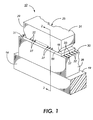
- Figure 1 is an enlarged schematic isometric view of an example of a printhead mounted on a daughter board showing the droplet emitting nozzles.
- Figure 2 is an enlarged cross-sectional view of Figure 1 as viewed along the line 2-2 thereof and showing the electrode passivation and ink flow path between the manifold and the ink channels.
- Figure 3 is an enlarged cross-sectional view of an alternate embodiment of the printhead in Figure 1 as viewed along the line 2-2 thereof.
- the present invention is directed to a composition
- a composition comprising a polymer with a weight average molecular weight of from about 1,000 to about 100,000, said polymer containing at least some monomer repeat units with photosensitivity-imparting substituents which enable crosslinking or chain extension of the polymer upon exposure to actinic radiation, said polymer also containing at least one thermal sensitivity-imparting group which enables further crosslinking or chain extension of the polymer upon exposure to heat, said polymer being selected from the group consisting of polysulfones, polyphenylenes, polyether sulfones, polyimides, polyamide imides, polyarylene ethers, polyphenylene sulfides, polyarylene ether ketones, phenoxy resins, polycarbonates, polyether imides, polyquinoxalines, polyquinolines, polybenzimidazoles, polybenzoxazoles, polybenzothiazoles, polyoxadiazoles, copolymers thereof, and mixtures thereof.
- the polymers of the present invention are generally selected from the class of high performance polymers, which tend to be stable at high temperatures of, for example, greater than about 250°C, highly aromatic, and exhibit little or no flowing at temperatures in excess of about 150°C.
- High performance polymers are often processed in special solvents or at temperatures above those at which their use is intended, and are useful for high temperature structural and adhesive applications. While most high performance polymers are thermoplastic, many have glass transition temperatures in excess of about 200°C and some, such as phenolics, tend to be thermosetting.
- high performance polymers suitable for the present invention include polysulfones, such as those of the formulae and wherein R is an alkyl group, preferably with from 1 to about 12 carbon atoms, a substituted alkyl group, an aryl group, preferably with from 6 to about 24 carbon atoms, a substituted aryl group, an arylalkyl group, preferably with from 7 to about 36 carbon atoms, or a substituted arylalkyl group, and n is an integer representing the number of repeating monomer units, polyphenylenes, such as those of the formula wherein n is an integer representing the number of repeating monomer units, polyether sulfones, such as those of the formulae and wherein R is an alkyl group, preferably with from 1 to about 12 carbon atoms, a substituted alkyl group, an aryl group, preferably with from 6 to about 24 carbon atoms, a substituted aryl group, an arylalkyl group, preferably
- substituents on the substituted alkyl, aryl, and arylalkyl groups include (but are not limited to) hydroxy groups, amine groups, imine groups, ammonium groups, pyridine groups, pyridinium groups, ether groups, aldehyde groups, ketone groups, ester groups, amide groups, carboxylic acid groups, carbonyl groups, thiocarbonyl groups, sulfate groups, sulfonate groups, sulfide groups, sulfoxide groups, phosphine groups, phosphonium groups, phosphate groups, cyano groups, nitrile groups, mercapto groups, nitroso groups, halogen atoms, nitro groups, sulfone groups, acyl groups, acid anhydride groups, azide groups, mixtures thereof, and the like, wherein two or more substituents can be joined together to form a ring.
- any of the phenyl groups and B groups shown in the above general formulae can also bear one or more of any of the above substituents as well as alkyl groups, preferably with from 1 to about 12 carbon atoms, substituted alkyl groups, aryl groups, preferably with from 6 to about 24 carbon atoms, substituted alkyl groups, arylalkyl groups, preferably with from 7 to about 26 carbon atoms, substituted arylalkyl groups, or the like, wherein two or more substituents can be joined together to form a ring.
- the photopatternable polymer is of the following formula: wherein Y and Z each, independently of the others, can be (but are not limited to) alkyl groups, including saturated, unsaturated, and cyclic alkyl groups, preferably with from 1 to about 15 carbon atoms, substituted alkyl groups, including saturated, unsaturated, and cyclic substituted alkyl groups, preferably with from 1 to about 15 carbon atoms, aryl groups, preferably with from 6 to about 24 carbon atoms, substituted aryl groups, preferably with from 6 to about 24 carbon atoms, arylalkyl groups, preferably with from 7 to about 30 carbon atoms, substituted arylalkyl groups, preferably with from 7 to about 30 carbon atoms, oxygen atoms (-O-), sulfur atoms (-S-), carbonyl groups (-CO-), sulfone groups (-SO 2 -), amine groups, imine groups, ammonium groups, pyridine groups, pyri
- x is such that the weight average molecular weight of the material is from about 1,000 to about 100,000, preferably from about 1,000 to about 65,000, more preferably from about 3,000 to about 40,000, even more preferably from about 10,000 to about 40,000, and most preferably from about 15,000 to about 25,000, although the value can be outside these ranges.
- the value of x will depend on the molecular weight of the monomers, and preferred values for x are smaller for larger monomers than they are for smaller monomers. For example, when the polymer is a polystyrene, preferred values of x are from about 5 to about 330, although the value can be outside this range.
- x is an integer of from about 5 to about 70, and more preferably from about 8 to about 50, although the value of n can be outside these ranges.
- a suitable polymer for the present invention is of the formula wherein x is an integer representing the number of repeating monomer units, and preferably is from about 5 to about 330, although the value can be outside this range.
- Polymers of these general formulae, including those having chloromethyl substituents thereon, can be made by known methods, such as those set forth in, for example, S. Imamura et al., "High Performance Electron Negative Resist, Chloromethylated Polystyrene: A Study on Molecular Parameters," J . of Applied Polymer Science, Vol. 27, p. 937 (1982); S.
- the photopatternable polymer is of the following formula: or wherein x is an integer of 0 or 1, A is -O-, -C(CH 3 ) 2 -, or mixtures thereof, B is wherein v is an integer of from 1 to about 20, and preferably from 1 to about 10, wherein z is an integer of from 2 to about 20, and preferably from 2 to about 10, wherein u is an integer of from 1 to about 20, and preferably from 1 to about 10, wherein w is an integer of from 1 to about 20, and preferably from 1 to about 10, other similar bisphenol derivatives, or mixtures thereof, and n is an integer representing the number of repeating monomer units.
- n is such that the weight average molecular weight of the material typically is from about 1,000 to about 100,000, preferably from about 1,000 to about 65,000, more preferably from about 1,000 to about 40,000, and even more preferably from about 3,000 to about 25,000, although the weight average molecular weight can be outside these ranges.
- n is an integer of from about 2 to about 70, more preferably from about 5 to about 70, and even more preferably from about 8 to about 50, although the value of n can be outside these ranges.
- the phenyl groups and the A and/or B groups may also be substituted, although the presence of two or more substituents on the B group ortho to the oxygen groups can render substitution difficult.
- Substituents can be present on the polymer either prior to or subsequent to the placement of photosensitivity-imparting functional groups thereon. Substituents can also be placed on the polymer during the process of placement of photosensitivity-imparting functional groups thereon.
- substituents include (but are not limited to) alkyl groups, including saturated, unsaturated, and cyclic alkyl groups, preferably with from 1 to about 6 carbon atoms, substituted alkyl groups, including saturated, unsaturated, and cyclic substituted alkyl groups, preferably with from 1 to about 6 carbon atoms, aryl groups, preferably with from 6 to about 24 carbon atoms, substituted aryl groups, preferably with from 6 to about 24 carbon atoms, arylalkyl groups, preferably with from 7 to about 30 carbon atoms, substituted arylalkyl groups, preferably with from 7 to about 30 carbon atoms, alkoxy groups, preferably with from 1 to about 6 carbon atoms, substituted alkoxy groups, preferably with from 1 to about 6 carbon atoms, aryloxy groups, preferably with from 6 to about 24 carbon atoms, substituted aryloxy groups, preferably with from 6 to about 24 carbon atoms, arylalkyloxy groups,
- the photopatternable polymers of the present invention contain in at least some of the monomer repeat units thereof photosensitivity-imparting substituents which enable crosslinking or chain extension of the polymer upon exposure to actinic radiation.
- Radiation which activates crosslinking or chain extension can be of any desired source and any desired wavelength, including (but not limited to) visible light, infrared light, ultraviolet light, electron beam radiation, x-ray radiation, or the like.
- suitable photosensitivity imparting groups include unsaturated ester groups, such as acryloyl groups, methacryloyl groups, cinnamoyl groups, crotonoyl groups, ethacryloyl groups, oleoyl groups, linoleoyl groups, maleoyl groups, fumaroyl groups, itaconoyl groups, citraconoyl groups, phenylmaleoyl groups, and esters of 3-hexene-1,6-dicarboxylic acid.
- alkylcarboxymethylene and ether groups Under certain conditions, such as imaging with electron beam, deep ultraviolet, or x-ray radiation, halomethyl groups are also photoactive.
- Epoxy groups, allyl ether groups, hydroxyalkyl groups, and unsaturated ammonium, unsaturated phosphonium, and unsaturated ether groups are also suitable photoactive groups.
- the photopatternable polymers containing these groups can be prepared by any suitable or desired process.
- the desired functional group or groups can be applied directly to the polymer.
- one or more intermediate materials can be prepared.
- the polymer backbone can be functionalized with a substituent which allows for the facile derivatization of the polymer backbone, such as hydroxyl groups, carboxyl groups, haloalkyl groups such as chloromethyl groups, hydroxyalkyl groups such as hydroxymethyl groups, methoxy methyl groups, and alkylcarboxymethylene groups.
- Unsaturated ester groups can be placed on the polymer backbone by any suitable or desired process, including the processes described in US Serial No. 08/697,761.
- substitution of the polymer can be accomplished by reacting the polymer in solution with (a) the appropriate unsaturated acid (such as acrylic acid, methacrylic acid, cinnamic acid, crotonic acid, ethacrylic acid, oleic acid, linoleic acid, maleic acid, fumaric acid, itaconic acid, citraconic acid, phenylmaleic acid, 3-hexene-1,6-dicarboxylic acid, or the like), and (b) a formaldehyde source (i.e., either formaldehyde or a material which, under the conditions of the reaction, generates formaldehyde; examples of formaldehyde sources in addition to formaldehyde include paraformaldehyde, trioxane, methylal, dimethoxymethane, and the like).
- the reaction is direct acid catalyzed; the polymer is dissolved in a suitable solvent and is allowed to react with the formaldehyde source at about 105°C in the presence of catalytic amounts of para-toluenesulfonic acid.
- solvents suitable for the reaction include 1,1,2,2-tetrachloroethane and, if a suitable pressure reactor is used, methylene chloride.
- the reactants are present in relative amounts with respect to each other (by weight) of about 10 parts polymer, about 5 parts formaldehyde source, about 1 part para-toluenesulfonic acid, about 15.8 parts of the appropriate acid (i.e., acrylic acid, methacrylic acid, or the like), about 0.2 parts hydroquinone methyl ether, and about 162 parts 1,1,2,2-tetrachloroethane.
- the polymers can also be substituted with photosensitivity-imparting groups such as unsaturated ester groups or the like by first preparing the haloalkylated derivative and then replacing at least some of the haloalkyl groups with unsaturated ester groups, as, for example, described in US Serial No. 08/705,479.
- the haloalkylated polymer can be substituted with unsaturated ester groups by reacting the haloalkylated polymer with an unsaturated ester salt in solution.
- suitable reactants include selected salts of Groups IA, IIB, IIIB, IVB, VB, VIB, VIIB, VIIIB, IB, IIB, IIIA, IVA, of the periodic table with the appropriate unsaturated ester, such as the ester salts of acrylic acid, methacrylic acid, cinnamic acid, crotonic acid, ethacrylic acid, oleic acid, linoleic acid, maleic acid, fumaric acid, itaconic acid, citraconic acid, phenylmaleic acid, 3-hexene-1,6-dicarboxylic acid, and the like, with specific examples including sodium, potassium, quaternary ammonium, phosphonium, and the like salts of acrylate, methacrylate, cinnamate, and the like.
- solvents suitable for the reaction include polar aprotic solvents such as N,N-dimethylacetamide, dimethylsulfoxide, N-methylpyrrolidinone, and di
- Haloalkylated polymer can be allyl ether substituted or epoxidized by first reacting the haloalkylated polymer with an unsaturated alcohol salt, such as an allyl alcohol salt, in solution.
- an unsaturated alcohol salt such as an allyl alcohol salt
- suitable unsaturated alcohol salts and allyl alcohol salts include sodium 2-allylphenolate, sodium 4-allylphenolate, sodium allyl alcoholate, corresponding salts with lithium, potassium, cesium, rubidium, ammonium, quaternary alkyl ammonium compounds, and the like.
- An unsaturated alcohol salt can be generated by the reaction of the alcohol with a base, such as sodium hydride, or sodium hydroxide.
- the salt displaces the halide of the haloalkyl groups at between about 25 and about 100°C.
- solvents suitable for the reaction include polar aprotic solvents such as N,N-dimethylacetamide, dimethylsulfoxide, N-methylpyrrolidinone, dimethylformamide, and tetrahydrofuran.
- the reactants are present in relative amounts with respect to each other of from about 1 to about 50 molar equivalents of unsaturated alcohol salt per haloalkyl group to be substituted, although the relative amounts can be outside this range.
- the reactants are present in solution in amounts of from about 5 to about 50 percent by weight solids, and preferably about 10 percent by weight solids, although the relative amounts can be outside this range.
- the haloalkylated polymer can be substituted with a photosensitivity-imparting, water-solubility-enhancing (or water-dispersability-enhancing) group by reacting the haloalkylated polymer with an unsaturated amine, phosphine, or alcohol, as, for example, described in US Serial No. 08/697,760.
- Suitable reactants include N,N-dimethyl ethyl methacrylate, N,N-dimethyl ethyl acrylate, wherein R is H or CH 3 and n is an integer of from 1 to about 50.
- the polymer is substituted with two different functional groups, one of which imparts photosensitivity to the polymer and one of which imparts water solubility or water dispersability to the polymer.
- reactants which can be reacted with the polymer to substitute the polymer with suitable water solubility enhancing groups or water dispersability enhancing groups include tertiary amines of the general formula which add to the polymer quaternary ammonium groups of the general formula wherein R 1 , R 2 , and R 3 each, independently of the others, can be alkyl groups, typically with from 1 to about 30 carbon atoms, substituted alkyl groups, aryl groups, typically with from 6 to about 18 carbon atoms, substituted aryl groups, arylalkyl groups, typically with from 7 to about 19 carbon atoms, and substituted arylalkyl groups, and X represents a halogen atom, such as fluorine, chlorine, bromine, or iodine; tertiary phosphine
- the hydroxymethylation of a polymer can be accomplished by reacting the polymer in solution with formaldehyde or paraformaldehyde and a base, such as sodium hydroxide, potassium hydroxide, calcium hydroxide, ammonium hydroxide, or tetramethylammonium hydroxide.
- a base such as sodium hydroxide, potassium hydroxide, calcium hydroxide, ammonium hydroxide, or tetramethylammonium hydroxide.
- Polymers can also be hydroxyalkylated by first preparing the haloalkylated derivative and then replacing at least some of the haloalkyl groups with hydroxyalkyl groups, as, for example, described in US Serial No. 08/705,365.
- the haloalkylated polymer can be hydroxyalkylated by alkaline hydrolysis of the haloalkylated polymer.
- the hydroxy groups replace the halide atoms in the haloalkyl groups on the polymer; accordingly, the number of carbon atoms in the haloalkyl group generally corresponds to the number of carbon atoms in the hydroxyalkyl group.
- Suitable reactants include sodium hydroxide, potassium hydroxide, calcium hydroxide, ammonium hydroxide, tetraalkyl ammonium hydroxides, such as tetrabutyl ammonium hydroxide, and the like.
- solvents suitable for the reaction include 1,1,2,2-tetrachloroethane, methylene chloride, and water.
- the reactants are present in relative amounts with respect to each other by weight of about 13.8 parts haloalkylated polymer, about 50 parts solvent, and about 30.6 parts base (containing 23 parts tetrabutylammonium hydroxide in water). After a clear solution is obtained, 30 milliliters of sodium hydroxide (50 percent aqueous solution) is added. After 16 hours at about 25°C, the organic layer is washed with water, dried over magnesium sulfate, and poured into methanol (1 gallon) to precipitate the polymer.
- haloalkylating polymers include reaction of the polymers with formaldehyde and hydrochloric acid, bischloromethyl ether, chloromethyl methyl ether, octylchloromethyl ether, or the like, generally in the presence of a Lewis acid catalyst. Bromination of a methyl group on the polymer can also be accomplished with elemental bromine via a free radical process initiated by, for example, a peroxide initiator or light. Halogen atoms can be substituted for other halogens already on a halomethyl group by, for example, reaction with the appropriate hydrohalic acid or halide salt.
- One specific process suitable for haloalkylating the polymer entails reacting the polymer with an acetyl halide, such as acetyl chloride, and dimethoxymethane in the presence of a halogen-containing Lewis acid catalyst, such as those of the general formula M n ⁇ X n wherein n is an integer of 1, 2, 3, 4, or 5, M represents a boron atom or a metal atom, such as tin, aluminum, zinc, antimony, iron (III), gallium, indium, arsenic, mercury, copper, platinum, or palladium, and X represents a halogen atom, such as fluorine, chlorine, bromine, or iodine, with specific examples including SnCl 4 , AlCl 3 , ZnCl 2 , AlBr 3 , BF 3 , SbF 5 , Fel 3 , GaBr 3 , InCl 3 , Asl 5 , HgBr 2 , CuC
- the polymers of the present invention also contain at least one thermal sensitivity-imparting substituent which enables further crosslinking or chain extension of the polymer upon exposure to temperatures of about 140°C and higher.
- suitable thermal sensitivity imparting groups include ethynyl groups, such as those of the formula ⁇ (R) a ⁇ C ⁇ C-R' wherein R is or a is an integer of 0 or 1, and R' is a hydrogen atom or a phenyl group, ethylenic linkage-containing groups, such as allyl groups, including those of the formula wherein X and Y each, independently of the other, are hydrogen atoms or halogen atoms, such as fluorine, chlorine, bromine, or iodine, vinyl groups, including those of the formula wherein R is an alkyl group, including both saturated, unsaturated, linear, branched, and cyclic alkyl groups, preferably with from 1 to about 30 carbon atoms, more preferably with from 1 to about 11 carbon
- the thermal sensitivity imparting groups can be present either as terminal end groups on the polymer or as groups which are pendant from one or more monomer repeat units within the polymer chain.
- the thermal sensitivity imparting groups are present as terminal end groups, one or both polymer ends can be terminated with the thermal sensitivity imparting group (or more, if the polymer is crosslinked and has more than two termini).
- the thermal sensitivity imparting groups are substituents on one or more monomer repeat units of the polymer, any desired or suitable degree of substitution can be employed.
- the degree of substitution is from about 1 to about 4 thermal sensitivity imparting groups per repeat monomer unit, although the degree of substitution can be outside this range.
- the degree of substitution is from about 0.5 to about 5 milliequivalents of thermal sensitivity imparting group per gram of polymer, and more preferably from about 0.75 to about 1.5 milliequivalents per gram, although the degree of substitution can be outside this range.
- the thermal sensitivity imparting groups can be placed on the polymer by any suitable or desired synthetic method. Processes for putting the above mentioned thermal sensitivity imparting groups on polymers are disclosed in, for example, "Polyimides," C. E. Sroog, Prog. Polym. Sci., Vol. 16, 561-694 (1991); F. E. Arnold and L. S. Tan, Symposium on Recent Advances in Polyimides and Other High Performance Polymers, Reno, NV (July 1987); L. S. Tan and F. E. Arnold, J. Polym. Sci. Part A, 26 , 1819 (1988); U. S. Patent 4,973,636; and U.S. Patent 4,927,907.
- a functional group can behave as either a photosensitivity-imparting group or a thermal sensitivity imparting group.
- at least two different groups are present on the polymer, one of which functions primarily as a photosensitivity-imparting group and one of which functions primarily as a thermal sensitivity imparting group. Either the two groups are selected so that the thermal sensitivity imparting group does not react or crosslink when exposed to actinic radiation at a level to which the photosensitivity-imparting group is sensitive, or photocuring is halted while at least some thermal sensitivity imparting groups remain intact and unreacted or uncrosslinked on the polymer.
- the thermal sensitivity imparting group is one which reacts at a temperature in excess of the glass transition temperature of the polymer subsequent to crosslinking or chain extension via photoexposure.
- the polymers of the present invention are cured in a two-stage process which entails (a) exposing the polymer to actinic radiation, thereby causing the polymer to become crosslinked or chain extended through the photosensitivity-imparting groups; and (b) subsequent to step (a), heating the polymer to a temperature of at least 140°C, thereby causing further crosslinking or chain extension of the polymer through the thermal sensitivity imparting groups.
- the temperature selected for the second, thermal cure step generally depends on the thermal sensitivity imparting group which is present on the polymer.
- ethynyl groups preferably are cured at temperatures of from about 150 to about 300°C.
- Halomethyl groups preferably are cured at temperatures of from about 150 to about 260°C.
- Hydroxymethyl groups preferably are cured at temperatures of from about 150 to about 250°C.
- Phenylethynyl phenyl groups preferably are cured at temperatures of greater than about 250°C.
- Vinyl groups preferably are cured at temperatures of from about 80 to about 250°C.
- Allyl groups preferably are cured at temperatures of over about 200°C.
- Epoxy groups preferably are cured at temperatures of about 150°C.
- Maleimide groups preferably are cured at temperatures of from about 200 to about 300°C.
- Benzocyclobutene groups preferably are cured at temperatures of over about 200°C.
- 5-Norbornene-2,3-dicarboximidogroups preferably are cured at temperatures of from about 200 to about 300°C.
- Vinyl ether groups preferably are cured at temperatures of about 150°C.
- Phenolic groups in the presence of hydroxymethyl or halomethyl groups preferably are cured at temperatures of from about 150 to about 210°C.
- Alkylcarboxylate groups preferably are cured at temperatures of from about 150 to about 250°C. Curing temperatures usually do not exceed about 400°C, although higher temperatures can be employed provided that decomposition of the polymer does not occur. Higher temperature cures preferably take place in an oxygen-excluded environment.
- Reaction of the phenylethynyl end groups serves to chain-extend the network.
- Hydroxymethyl and halo groups are also preferred when the photopatternable polymer has a glass transition temperature of less than about 150°C. Hydroxymethyl and halomethyl groups on phenolic ends are particularly reactive and serve to chain-extend the network. The fact that this chain extension occurs at temperatures significantly in excess of the glass transition temperature of the polymer facilitates the chain extension reaction, relaxes stresses in the crosslinked film, and allows for the extrusion of thermally labile alkyl fragments introduced in the photoactivation of the backbone.
- Phenolic end groups can be obtained by adjusting the stoichiometry of the coupling reaction in the formation of polyarylene ether ketones; for example, excess bisphenol A is used when bisphenol A is the B group.
- Halomethyl groups are particularly preferred. Halomethyl groups react at a temperature in excess of 150°C and extensively crosslink the polymer by the elimination of hydrochloric acid and the formation of methylene bridges. When the photoexposed crosslinked polymer has a glass transition temperature of less than about 150°C, halomethyl groups are particularly preferred.
- the terminal groups on the polymer can be selected by the stoichiometry of the polymer synthesis.
- a polymer is prepared by the reaction of 4,4'-dichlorobenzophenone and bis-phenol A in the presence of potassium carbonate in N,N-dimethylacetamide
- the resulting polymer generally is bis-phenol A-terminated (wherein the bis-phenol A moiety may or may not have one or more hydroxy groups thereon), and the resulting polymer typically has a polydispersity (M w /M n ) of from about 2 to about 3.5.
- the polydispersity of the polymer can rise to the range of from about 4 to about 6.
- the reaction time is approximately half that required for the bis-phenol A excess reaction
- the resulting polymer generally is benzophenone-terminated (wherein the benzophenone moiety may or may not have one or more chlorine atoms thereon), and the resulting polymer typically has a polydispersity of from about 2 to about 3.5.
- the polydispersity of the polymer typically remains in the range of from about 2 to about 3.5.
- Specific functional groups can also be present on these terminal "A” groups or “B” groups, such as ethynyl groups or other thermally sensitive groups, hydroxy groups which are attached to the aromatic ring on an "A” or “B” group to form a phenolic moiety, halogen atoms which are attached to the "A” or “B” group, or the like.
- Polymers with end groups derived from the "A” group may be preferred for some applications because both the syntheses and some of the reactions of these materials to place substituents thereon may be easier to control and may yield better results with respect to, for example, cost, molecular weight, molecular weight range, and polydispersity (M w /M n ) compared to polymers with end groups derived from the "B” group, such as bis-phenol A groups (having one or more hydroxy groups on the aromatic rings thereof) or other phenolic groups.
- end groups derived from the "A” group such as benzophenone groups or halogenated benzophenone groups
- haloalkylation reaction in particular proceeds most rapidly on the phenolic tails when the polymer is bis-phenol A terminated.
- halomethylated groups on phenolic-terminated polymers may be particularly reactive to subsequent crosslinking or chain extension.
- halomethylation does not take place on the terminal aromatic groups with electron withdrawing substituents, such as benzophenone, halogenated benzophenone, or the like.
- any residual halogen atoms or haloalkyl groups on the photopatternable polymer can be converted to methoxy groups, hydroxide groups, acetoxy groups, amine groups, or the like by any desired process, including those processes disclosed hereinabove, those disclosed in, for example, British Patent 863,702, Chem Abstr. 55 , 18667b (1961).
- the photopatternable polymer can be cured by uniform exposure to actinic radiation at wavelengths and/or energy levels capable of causing crosslinking or chain extension of the polymer through the photosensitivity-imparting groups.
- the photopatternable polymer is developed by imagewise exposure of the material to radiation at a wavelength and/or at an energy level to which the photosensitivity-imparting groups are sensitive.
- a photoresist composition will contain the photopatternable polymer, an optional solvent for the photopatternable polymer, an optional sensitizer, and an optional photoinitiator. Solvents may be particularly desirable when the uncrosslinked photopatternable polymer has a high T g .
- the solvent and photopatternable polymer typically are present in relative amounts of from 0 to about 99 percent by weight solvent and from about 1 to 100 percent polymer, preferably are present in relative amounts of from about 20 to about 60 percent by weight solvent and from about 40 to about 80 percent by weight polymer, and more preferably are present in relative amounts of from about 30 to about 60 percent by weight solvent and from about 40 to about 70 percent by weight polymer, although the relative amounts can be outside these ranges.
- Sensitizers absorb light energy and facilitate the transfer of energy to unsaturated bonds which can then react to crosslink or chain extend the resin. Sensitizers frequently expand the useful energy wavelength range for photoexposure, and typically are aromatic light absorbing chromophores. Sensitizers can also lead to the formation of photoinitiators, which can be free radical or ionic.
- the optional sensitizer and the photopatternable polymer typically are present in relative amounts of from about 0.1 to about 20 percent by weight sensitizer and from about 80 to about 99.9 percent by weight photopatternable polymer, and preferably are present in relative amounts of from about 1 to about 10 percent by weight sensitizer and from about 90 to about 99 percent by weight photopatternable polymer, although the relative amounts can be outside these ranges.
- Photoinitiators generally generate ions or free radicals which initiate polymerization upon exposure to actinic radiation.
- the optional photoinitiator and the photopatternable polymer typically are present in relative amounts of from about 0.1 to about 20 percent by weight photoinitiator and from about 80 to about 99.9 percent by weight photopatternable polymer, and preferably are present in relative amounts of from about 1 to about 10 percent by weight photoinitiator and from about 90 to about 99 percent by weight photopatternable polymer, although the relative amounts can be outside these ranges.
- a single material can also function as both a sensitizer and a photoinitiator.
- sensitizers and photoinitiators examples include Michler's ketone (Aldrich Chemical Co.), Darocure 1173, Darocure 4265, Irgacure 184, Irgacure 261, and Irgacure 907 (available from Ciba-Geigy, Ardsley, New York), and mixtures thereof. Further background material on initiators is disclosed in, for example, Ober et al., J.M.S. - Pure Appl. Chem., A30 (12), 877-897 (1993); G. E. Green, B. P. Stark, and S. A. Zahir, "Photocrosslinkable Resin Systems," J. Macro. Sci. -- Revs. Macro.
- Sensitizers are available from, for example, Aldrich Chemical Co., Milwaukee, WI, and Pfaltz and Bauer, Waterberry, CT. Benzophenone and its derivatives can function as photosensitizers. Triphenylsulfonium and diphenyl iodonium salts are examples of typical cationic photoinitiators.
- Inhibitors may also optionally be present in the photoresist containing the photopatternable polymer.
- suitable inhibitors include MEHQ, a methyl ether of hydroquinone, of the formula t-butylcatechol, of the formula hydroquinone, of the formula the inhibitor typically present in an amount of from about 500 to about 1,500 parts per million by weight of a photoresist solution containing about 40 percent by weight polymer solids, although the amount can be outside this range.
- photosensitivity-imparting groups which are indicated above as being capable of enabling crosslinking or chain extension of the polymer upon exposure to actinic radiation can also enable crosslinking or chain extension of the polymer upon exposure to elevated temperatures; thus the polymers of the present invention can also, if desired, be used in applications wherein thermal curing is employed.
- Photopatternable polymeric materials of the present invention can be used as components in ink jet printheads.
- the printheads of the present invention can be of any suitable configuration.
- An example of a suitable configuration, suitable in this instance for thermal ink jet printing, is illustrated schematically in Figure 1, which depicts an enlarged, schematic isometric view of the front face 29 of a printhead 10 showing the array of droplet emitting nozzles 27.
- the lower electrically insulating substrate or heating element plate 28 has the heating elements 34 and addressing electrodes 33 patterned on surface 30 thereof, while the upper substrate or channel plate 31 has parallel grooves 20 which extend in one direction and penetrate through the upper substrate front face edge 29.
- grooves 20 terminate at slanted wall 21, the floor 41 of the internal recess 24 which is used as the ink supply manifold for the capillary filled ink channels 20, has an opening 25 therethrough for use as an ink fill hole.
- the surface of the channel plate with the grooves are aligned and bonded to the heater plate 28, so that a respective one of the plurality of heating elements 34 is positioned in each channel, formed by the grooves and the lower substrate or heater plate.
- Ink enters the manifold formed by the recess 24 and the lower substrate 28 through the fill hole 25 and by capillary action, fills the channels 20 by flowing through an elongated recess 38 formed in the thick film insulative layer 18.
- the ink at each nozzle forms a meniscus, the surface tension of which prevents the ink from weeping therefrom.
- the addressing electrodes 33 on the lower substrate or channel plate 28 terminate at terminals 32.
- the upper substrate or channel plate 31 is smaller than that of the lower substrate in order that the electrode terminals 32 are exposed and available for wire bonding to the electrodes on the daughter board 19, on which the printhead 10 is permanently mounted.
- Layer 18 is a thick film passivation layer, discussed later, sandwiched between the upper and lower substrates. This layer is etched to expose the heating elements, thus placing them in a pit, and is etched to form the elongated recess to enable ink flow between the manifold 24 and the ink channels 20. In addition, the thick film insulative layer is etched to expose the electrode terminals.
- FIG. 1 A cross sectional view of Figure 1 is taken along view line 2-2 through one channel and shown as Figure 2 to show how the ink flows from the manifold 24 and around the end 21 of the groove 20 as depicted by arrow 23.
- a plurality of sets of bubble generating heating elements 34 and their addressing electrodes 33 can be patterned on the polished surface of a single side polished (100) silicon wafer.
- the polished surface of the wafer is coated with an underglaze layer 39 such as silicon dioxide, having a typical thickness of from about 5,000 Angstroms to about 2 microns, although the thickness can be outside this range.
- the resistive material can be a doped polycrystalline silicon, which can be deposited by chemical vapor deposition (CVD) or any other well known resistive material such as zirconium boride (ZrB 2 ).
- the common return and the addressing electrodes are typically aluminum leads deposited on the underglaze and over the edges of the heating elements.
- the common return ends or terminals 37 and addressing electrode terminals 32 are positioned at predetermined locations to allow clearance for wire bonding to the electrodes (not shown) of the daughter board 19, after the channel plate 31 is attached to make a printhead.
- the common return 35 and the addressing electrodes 33 are deposited to a thickness typically of from about 0.5 to about 3 micrometers (microns), although the thickness can be outside this range, with the preferred thickness being 1.5 micrometers (microns).
- polysilicon heating elements may be subsequently oxidized in steam or oxygen at a relatively high temperature, typically about 1,100°C although the temperature can be above or below this value, for a period of time typically of from about 50 to about 80 minutes, although the time period can be outside this range, prior to the deposition of the aluminum leads, in order to convert a small portion of the polysilicon to SiO 2 .
- the heating elements are thermally oxidized to achieve an overglaze (not shown) of SiO 2 with a thickness typically of from about 50nm (500 Angstroms) to about 1 micrometer (micron), although the thickness can be outside this range, which has good integrity with substantially no pinholes.
- polysilicon heating elements are used and an optional silicon dioxide thermal oxide layer 17 is grown from the polysilicon in high temperature steam.
- the thermal oxide layer is typically grown to a thickness of from about 0.5 to about 1 micrometer (micron), although the thickness can be outside this range, to protect and insulate the heating elements from the conductive ink.
- the thermal oxide is removed at the edges of the polysilicon heating elements for attachment of the addressing electrodes and common return, which are then patterned and deposited. If a resistive material such as zirconium boride is used for the heating elements, then other suitable well known insulative materials can be used for the protective layer thereover.
- a tantalum (Ta) layer (not shown) can be optionally deposited, typically to a thickness of about 1 micron, although the thickness can be above or below this value, on the heating element protective layer 17 for added protection thereof against the cavitational forces generated by the collapsing ink vapor bubbles during printhead operation.
- the tantalum layer is etched off all but the protective layer 17 directly over the heating elements using, for example, CF 4 /O 2 plasma etching.
- the aluminum common return and addressing electrodes typically are deposited on the underglaze layer and over the opposing edges of the polysilicon heating elements which have been cleared of oxide for the attachment of the common return and electrodes.
- a film 16 is deposited over the entire wafer surface, including the plurality of sets of heating elements and addressing electrodes.
- the passivation film 16 provides an ion barrier which will protect the exposed electrodes from the ink.
- suitable ion barrier materials for passivation film 16 include polyimide, plasma nitride, phosphorous doped silicon dioxide, materials disclosed hereinafter as being suitable for insulative layer 18, and the like, as well as any combinations thereof.
- An effective ion barrier layer is generally achieved when its thickness is from about 100nm (1000 Angstroms) to about 10 micrometers (microns), although the thickness can be outside this range.
- passivation layer 16 preferably has a thickness of about 3 microns, although the thickness can be above or below this value. In 600 dpi printheads, the thickness of passivation layer 16 preferably is such that the combined thickness of layer 16 and layer 18 is about 25 micrometers (microns), although the thickness can be above or below this value.
- the passivation film or layer 16 is etched off of the terminal ends of the common return and addressing electrodes for wire bonding later with the daughter board electrodes. This etching of the silicon dioxide film can be by either the wet or dry etching method. Alternatively, the electrode passivation can be by plasma deposited silicon nitride (Si 3 N 4 ).
- a thick film type insulative layer 18, of a material to be discussed in further detail hereinbelow, is formed on the passivation layer 16, typically having a thickness of from about 10 to about 100 microns and preferably in the range of from about 25 to about 50 microns, although the thickness can be outside these ranges. Even more preferably, in 300 dpi printheads, layer 18 preferably has a thickness of about 30 micrometers (microns), and in 600 dpi printheads, layer 18 preferably has a thickness of from about 20 to about 22 micrometers (microns), although other thicknesses can be employed.
- the insulative layer 18 is photolithographically processed to enable etching and removal of those portions of the layer 18 over each heating element (forming recesses 26), the elongated recess 38 for providing ink passage from the manifold 24 to the ink channels 20, and over each electrode terminal 32, 37.
- the elongated recess 38 is formed by the removal of this portion of the thick film layer 18.
- the passivation layer 16 alone protects the electrodes 33 from exposure to the ink in this elongated recess 38.
- Figure 3 is a similar view to that of Figure 2 with a shallow anisotropically etched groove 40 in the heater plate, which is silicon, prior to formation of the underglaze 39 and patterning of the heating elements 34, electrodes 33 and common return 35.
- This recess 40 permits the use of only the thick film insulative layer 18 and eliminates the need for the usual electrode passivating layer 16. Since the thick film layer 18 is impervious to water and relatively thick (typically from about 20 to about 40 micrometers (microns), although the thickness can be outside this range), contamination introduced into the circuitry will be much less than with only the relatively thin passivation layer 16 well known in the art.
- the heater plate is a fairly hostile environment for integrated circuits. Commercial ink generally entails a low attention to purity.
- the active part of the heater plate will be at elevated temperature adjacent to a contaminated aqueous ink solution which undoubtedly abounds with mobile ions.
- the thick film insulative layer 18 provides improved protection for the active devices and provides improved protection, resulting in longer operating lifetime for the heater plate.
- At least two alignment markings (not shown) preferably are photolithographically produced at predetermined locations on the lower substrates 28 which make up the silicon wafer. These alignment markings are used for alignment of the plurality of upper substrates 31 containing the ink channels.
- the surface of the single sided wafer containing the plurality of sets of heating elements is bonded to the surface of the wafer containing the plurality of ink channel containing upper substrates subsequent to alignment.
- the channel plate is formed from a two side polished, (100) silicon wafer to produce a plurality of upper substrates 31 for the printhead.
- a pyrolytic CVD silicon nitride layer (not shown) is deposited on both sides.
- a via for fill hole 25 for each of the plurality of channel plates 31 and at least two vias for alignment openings (not shown) at predetermined locations are printed on one wafer side.
- the silicon nitride is plasma etched off of the patterned vias representing the fill holes and alignment openings.
- a potassium hydroxide (KOH) anisotropic etch can be used to etch the fill holes and alignment openings.
- the [111] planes of the (100) wafer typically make an angle of about 54.7 degrees with the surface of the wafer.
- the fill holes are small square surface patterns, generally of about 20 mils (500 microns) per side, although the dimensions can be above or below this value, and the alignment openings are from about 60 to about 80 mils (1.5 to 3 millimeters) square, although the dimensions can be outside this range.
- the alignment openings are etched entirely through the 20 mil (0.5 millimeter) thick wafer, while the fill holes are etched to a terminating apex at about halfway through to three-quarters through the wafer.
- the relatively small square fill hole is invariant to further size increase with continued etching so that the etching of the alignment openings and fill holes are not significantly time constrained.
- the opposite side of the wafer is photolithographically patterned, using the previously etched alignment holes as a reference to form the relatively large rectangular recesses 24 and sets of elongated, parallel channel recesses that will eventually become the ink manifolds and channels of the printheads.
- the surface 22 of the wafer containing the manifold and channel recesses are portions of the original wafer surface (covered by a silicon nitride layer) on which an adhesive, such as a thermosetting epoxy, will be applied later for bonding it to the substrate containing the plurality of sets of heating elements.
- the adhesive is applied in a manner such that it does not run or spread into the grooves or other recesses.
- the alignment markings can be used with, for example, a vacuum chuck mask aligner to align the channel wafer on the heating element and addressing electrode wafer.
- the two wafers are accurately mated and can be tacked together by partial curing of the adhesive.
- the heating element and channel wafers can be given precisely diced edges and then manually or automatically aligned in a precision jig.
- Alignment can also be performed with an infrared aligner-bonder, with an infrared microscope using infrared opaque markings on each wafer to be aligned, or the like.
- the two wafers can then be cured in an oven or laminator to bond them together permanently.
- the channel wafer can then be milled to produce individual upper substrates.
- the other ends of the channel groove 20 remain closed by end 21.
- the alignment and bonding of the channel plate to the heater plate places the ends 21 of channels 20 directly over elongated recess 38 in the thick film insulative layer 18 as shown in Figure 2 or directly above the recess 40 as shown in Figure 3 enabling the flow of ink into the channels from the manifold as depicted by arrows 23.
- the plurality of individual printheads produced by the final dicing are bonded to the daughter board and the printhead electrode terminals are wire bonded to the daughter board electrodes.
- a heater wafer with a phosphosilicate glass layer is spin coated with a solution of Z6020 adhesion promoter (0.01 weight percent in 95 parts methanol and 5 parts water, Dow Corning) at 3000 revolutions per minute for 10 seconds and dried at 100°C for between 2 and 10 minutes. The wafer is then allowed to cool at 25°C for 5 minutes before spin coating the photoresist containing the photopatternable polymer onto the wafer at between 1,000 and 3,000 revolutions per minute for between 30 and 60 seconds.
- Z6020 adhesion promoter 0.01 weight percent in 95 parts methanol and 5 parts water, Dow Corning
- the photoresist solution is made by dissolving polyarylene ether ketone with 0.75 acryloyl groups and 0.75 chloromethyl groups per repeat unit and a weight average molecular weight of 25,000 in N-methylpyrrolidinone at 40 weight percent solids with Michler's ketone (1.2 parts ketone per every 10 parts of 40 weight percent solids polymer solution).
- the film is heated (soft baked) in an oven for between 10 and 15 minutes at 70°C. After cooling to 25°C over 5 minutes, the film is covered with a mask and exposed to 365 nanometer ultraviolet light, amounting to between 150 and 1500 milliJoules per cm 2 .
- the exposed wafer is then heated at 70°C for 2 minutes post exposure bake, followed by cooling to 25°C over 5 minutes.
- the film is developed with 60:40 chloroform/cyclohexanone developer, washed with 90:10 hexanes/cyclohexanone, and then dried at 70°C for 2 minutes.
- a second developer/wash cycle is carried out if necessary to obtain a wafer with clean features.
- the processed wafer is transferred to an oven at 25°C, and the oven temperature is raised from 25 to 90°C at 2°C per minute. The temperature is maintained at 90°C for 2 hours, and then increased to 260°C at 2°C per minute. The oven temperature is maintained at 260°C for 2 hours and then the oven is turned off and the temperature is allowed to cool gradually to 25°C.
- thermal cure of the photoresist films is carried out under an inert atmosphere, such as nitrogen or one of the noble gases, such as argon, neon, krypton, xenon, or the like, there is markedly reduced oxidation of the developed film and improved thermal and hydrolytic stability of the resultant devices. Moreover, adhesion of developed photoresist film is improved to the underlying substrate. If a second layer is spin coated over the first layer, the heat cure of the first developed layer can be stopped between 80 and 260°C before the second layer is spin coated onto the first layer. A second thicker layer is deposited by repeating the above procedure a second time. This process is intended to be a guide in that procedures can be outside the specified conditions depending on film thickness and photoresist molecular weight. Films at 30 microns have been developed with clean features at 600 dots per inch.
- photoresist compositions of the present invention are free of particulates prior to coating onto substrates.
- the photoresist composition containing the photopatternable polymer is subjected to filtration through a 2 micron nylon filter cloth (available from Tetko).
- the photoresist solution is filtered through the cloth under yellow light or in the dark as a solution containing from about 30 to about 60 percent by weight solids using compressed air (up to about 60 psi) and a pressure filtration funnel.
- the photopatternable polymer is admixed with an epoxy resin in relative amounts of from about 75 parts by weight photopatternable polymer and about 25 parts by weight epoxy resin to about 90 parts by weight photopatternable polymer and about 10 parts by weight epoxy resin.
- the present invention also encompasses printing processes with printheads according to the present invention.
- One embodiment of the present invention is directed to an ink jet printing process which comprises (1) providing an ink jet printhead comprising a plurality of channels, wherein the channels are capable of being filled with ink from an ink supply and wherein the channels terminate in nozzles on one surface of the printhead, said printhead comprising (i) an upper substrate with a set of parallel grooves for subsequent use as ink channels and a recess for subsequent use as a manifold, the grooves being open at one end for serving as droplet emitting nozzles, (ii) a lower substrate in which one surface thereof has an array of heating elements and addressing electrodes formed thereon, and (iii) a thick film layer deposited on the surface of the lower substrate and over the heating elements and addressing electrodes and patterned to form recesses therethrough to expose the heating elements and terminal ends of the addressing electrodes, said thick film layer comprising a crosslinked or chain extended photopatternable polymer of
- a specific embodiment of this process is directed to a thermal ink jet printing process, wherein the droplets of ink are caused to be expelled from the nozzles by heating selected channels in an image pattern.
- the droplets can be expelled onto any suitable receiver sheet, such as fabric, plain paper such as Xerox® 4024 or 4010, coated papers, or transparency materials.
- a polymer of the formula wherein n represents the number of repeating monomer units was prepared as follows. Under argon in a glove bag, the following reagents were combined in a 500 milliliter, 3-neck, round-bottom flask equipped with an argon inlet, column, mechanical stirrer, and stopper: Nickel dichloride (0.324 grams), triphenylphosphine 15.7 grams, heated to 200°C before use), 2,2'-bipyridine (0.391 grams), zinc (16.1 grams, treated with glacial acetic acid, washed with diethyl ether and vacuum dried before use), and benzoyl-2,4-dichlorobenzene (12.5 grams, prepared as described in Example XLI) in 43.9 grams of N-methylpyrrolidinone, freshly distilled from sodium hydride.
- the green mixture was heated to 90°C oil bath set temperature. Within 20 minutes, the reaction mixture turned red-brown and became more red with time. After 16 hours of reaction at 90°C with constant stirring, the mixture was added to methanol and hydrochloric acid, and the polymer that precipitated was collected, washed with water, and then washed with methanol. The yield was 8.8 grams (70.4%) of vacuum dried polymer with a M n 1626, M p 1620, M w 2077, and M z 2643, as determined with gel permeation chromatography.
- a polymer of the formula wherein n represents the number of repeating monomer units was prepared as follows. Under argon in a glove bag, the following reagents were combined in a 500 milliliter, 3-neck, round-bottom flask equipped with an argon inlet, column, mechanical stirrer, and stopper: Nickel dichloride (Alpha high quality, 0.2 grams), triphenylphosphine (10.8 grams, vacuum dried), 2,2'-bipyridine (0.26 grams, vacuum dried), zinc (Cerac high purity, 14.7 grams), and 4'-methylbenzoyl-2,4 -dichlorobenzene (20 grams, prepared as described in Example XL) in 50 milliliters of N,N-dimethylacetamide.
- the mixture was heated to between 70 and 80°C oil bath set temperature. Within 20 minutes, the reaction mixture turned red-brown and became more red with time. After 16 hours of reaction at 80°C with constant stirring, the mixture was added to methanol and hydrochloric acid, and the polymer that precipitated was collected, washed with water, and then washed with methanol. The yield was 14.4 grams (72.0%) of vacuum dried polymer with a M n 3277, M p 5553, M w 6001, and M z 9841, as determined with gel permeation chromatography.
- a polymer of the formula wherein n represents the number of repeating monomer units was prepared as follows. Under argon in a glove bag, the following reagents were combined in a 500 milliliter, 3-neck, round-bottom flask equipped with an argon inlet, column, mechanical stirrer, and stopper: Nickel dichloride (Alpha high quality, 0.2 grams), triphenylphosphine (10.8 grams, vacuum dried), 2,2'-bipyridine (0.27 grams, vacuum dried), zinc (Cerac high purity, 14.4 grams), and 4'-methylbenzoyl-2,5-dichlorobenzene (20 grams, prepared as described in Example XLIV) in 50 milliliters of N,N-dimethylacetamide.
- the mixture was heated to between 70 and 80°C oil bath set temperature. Within 20 minutes, the reaction mixture turned red-brown and became more red with time. After 16 hours of reaction at 80°C with constant stirring, the mixture was added to methanol and hydrochloric acid, and the polymer that precipitated was collected, washed with water, and then washed with methanol. The yield was 16.6 grams (83.0%) of vacuum dried, light-yellow polymer with a M n 9,460, M p 29,312, M w 32,487, and M z 78,024, as determined with gel permeation chromatography.
- a polymer of the formula wherein n represents the number of repeating monomer units was prepared as follows. Under argon in a glove bag, the following reagents were combined in a 500 milliliter, 3-neck, round-bottom flask equipped with an argon inlet, column, mechanical stirrer, and stopper: Nickel dichloride (Alpha high quality, 0.2 grams), triphenylphosphine (10.8 grams, vacuum dried), 2,2'-bipyridine (0.27 grams, vacuum dried), zinc (Cerac high purity, 15 grams), and N,N-dimethylacetamide (50 milliliters).
- LaRC PETI obtained from NASA Langley Research Center
- a polymer blend containing 85 percent by weight of a polymer of the formula with ethynyl terminal end groups and 15 percent by weight of a polymer of the formula with ethynyl terminal end groups was spin coated onto silicon wafers and thermally imidized in a nitrogen purged environment. Thereafter, pieces of each polyimide coated wafer were soaked in a solution of 1 Molar tetramethyl ammonium hydroxide at 40°C and at 60°C. Subsequently, an ion exchange reaction was carried out with a cesium salt to label the hydrolyzed regions.
- the hydrolytic rate was faster for the LaRC 8515 than for the ethynyl-terminated LaRC PETI. While it is not wished to be limited to any particular theory, it is believed that while the two materials have the same backbone structure, the PETI is endcapped with a reactive endgroup which, it is believed, promotes crosslinking during the thermal imidization process, and that this crosslinking reduced the rate of hydrolytic damage.
Landscapes
- Physics & Mathematics (AREA)
- Spectroscopy & Molecular Physics (AREA)
- General Physics & Mathematics (AREA)
- Compositions Of Macromolecular Compounds (AREA)
- Particle Formation And Scattering Control In Inkjet Printers (AREA)
- Exposure And Positioning Against Photoresist Photosensitive Materials (AREA)
Applications Claiming Priority (2)
| Application Number | Priority Date | Filing Date | Title |
|---|---|---|---|
| US08/705,488 US6124372A (en) | 1996-08-29 | 1996-08-29 | High performance polymer compositions having photosensitivity-imparting substituents and thermal sensitivity-imparting substituents |
| US705488 | 1996-08-29 |
Publications (2)
| Publication Number | Publication Date |
|---|---|
| EP0827029A2 true EP0827029A2 (fr) | 1998-03-04 |
| EP0827029A3 EP0827029A3 (fr) | 1998-06-17 |
Family
ID=24833695
Family Applications (1)
| Application Number | Title | Priority Date | Filing Date |
|---|---|---|---|
| EP97306200A Withdrawn EP0827029A3 (fr) | 1996-08-29 | 1997-08-15 | Composition de polymères à haute performance |
Country Status (3)
| Country | Link |
|---|---|
| US (3) | US6124372A (fr) |
| EP (1) | EP0827029A3 (fr) |
| JP (1) | JPH1097073A (fr) |
Cited By (10)
| Publication number | Priority date | Publication date | Assignee | Title |
|---|---|---|---|---|
| EP0916499A1 (fr) * | 1997-11-17 | 1999-05-19 | Xerox Corporation | Procédé et matériau pour fabriquer une tête d'impression à jet d'encre |
| US6139920A (en) * | 1998-12-21 | 2000-10-31 | Xerox Corporation | Photoresist compositions |
| US6177238B1 (en) * | 1999-06-04 | 2001-01-23 | Xerox Corporation | Ink jet printheads containing arylene ether alcohol polymers and processes for their formation |
| US6260956B1 (en) | 1998-07-23 | 2001-07-17 | Xerox Corporation | Thermal ink jet printhead and process for the preparation thereof |
| US6273985B1 (en) | 1998-06-26 | 2001-08-14 | Xerox Corporation | Bonding process |
| US6716956B2 (en) | 2002-01-09 | 2004-04-06 | Xerox Corporation | Process for preparing polyarylene ethers |
| US6927273B2 (en) | 2002-12-17 | 2005-08-09 | Xerox Corporation | Process for preparing substituted polyarylene ethers |
| US7001978B2 (en) | 2003-11-19 | 2006-02-21 | Xerox Corporation | Unsaturated ester substituted polymers with reduced halogen content |
| US7067608B2 (en) | 2003-11-25 | 2006-06-27 | Xerox Corporation | Process for preparing branched polyarylene ethers |
| US7396895B2 (en) | 2003-11-25 | 2008-07-08 | Xerox Corporation | Branched polyarylene ethers and processes for the preparation thereof |
Families Citing this family (53)
| Publication number | Priority date | Publication date | Assignee | Title |
|---|---|---|---|---|
| US6294317B1 (en) * | 1999-07-14 | 2001-09-25 | Xerox Corporation | Patterned photoresist structures having features with high aspect ratios and method of forming such structures |
| US6686124B1 (en) * | 2000-03-14 | 2004-02-03 | International Business Machines Corporation | Multifunctional polymeric materials and use thereof |
| US6409316B1 (en) | 2000-03-28 | 2002-06-25 | Xerox Corporation | Thermal ink jet printhead with crosslinked polymer layer |
| JP2002138248A (ja) * | 2000-11-01 | 2002-05-14 | Fujitsu Ltd | 絶縁性樹脂膜形成性組成物および絶縁性樹脂膜 |
| US6364469B1 (en) * | 2000-12-06 | 2002-04-02 | Eastman Kodak Company | Continuous ink jet printing process |
| US6520628B2 (en) * | 2001-01-30 | 2003-02-18 | Hewlett-Packard Company | Fluid ejection device with substrate having a fluid firing device and a fluid reservoir on a first surface thereof |
| EP1383169B1 (fr) | 2001-04-23 | 2014-06-04 | Shin-Etsu Chemical Co., Ltd. | Element a rayonnement thermique |
| DE10137375A1 (de) * | 2001-07-31 | 2003-02-27 | Infineon Technologies Ag | Verwendung von Polybenzoxazolen (PBO) zum Kleben |
| KR100511100B1 (ko) * | 2002-07-12 | 2005-08-31 | 김미화 | 퍼플루오로스티렌 화합물, 이를 이용한 코팅액 및광도파로형 광소자 |
| DE10242708A1 (de) | 2002-09-13 | 2004-05-19 | Celanese Ventures Gmbh | Protonenleitende Membranen und deren Verwendung |
| US7323290B2 (en) * | 2002-09-30 | 2008-01-29 | Eternal Technology Corporation | Dry film photoresist |
| TWI262041B (en) * | 2003-11-14 | 2006-09-11 | Hitachi Chemical Co Ltd | Formation method of metal layer on resin layer, printed wiring board, and production method thereof |
| US20050126697A1 (en) * | 2003-12-11 | 2005-06-16 | International Business Machines Corporation | Photochemically and thermally curable adhesive formulations |
| JP5165829B2 (ja) * | 2004-02-26 | 2013-03-21 | 日東電工株式会社 | ロール状ウエハ加工用粘着シート |
| US7135122B2 (en) * | 2004-03-31 | 2006-11-14 | Freudenberg-Nok General Partnership | Polytetrafluoroethylene composites |
| US7309758B2 (en) | 2004-06-07 | 2007-12-18 | Battelle Energy Alliance, Llc | Polybenzimidazole compounds, polymeric media, and methods of post-polymerization modifications |
| US7259230B2 (en) * | 2004-06-07 | 2007-08-21 | Battelle Energy Alliance, Llc | Polybenzimidazole compounds, polymeric media, and methods of post-polymerization modifications |
| US7521508B2 (en) * | 2004-06-30 | 2009-04-21 | Freudenberg-Nok General Partnership | Electron beam inter-curing of plastic and elastomer blends |
| US7204574B2 (en) * | 2004-06-30 | 2007-04-17 | Lexmark International, Inc. | Polyimide thickfilm flow feature photoresist and method of applying same |
| US7342072B2 (en) | 2004-06-30 | 2008-03-11 | Freudenberg-Nok General Partnership | Bimodal compounds having an elastomeric moiety |
| US7244329B2 (en) * | 2004-06-30 | 2007-07-17 | Freudenberg-Nok General Partnership | Electron beam curing in a composite having a flow resistant adhesive layer |
| US7452577B2 (en) * | 2004-06-30 | 2008-11-18 | Freudenberg-Nok General Partnership | Electron beam curing of fabricated polymeric structures |
| US20060000801A1 (en) * | 2004-06-30 | 2006-01-05 | Park Edward H | Surface bonding in halogenated polymeric components |
| US7230038B2 (en) * | 2004-06-30 | 2007-06-12 | Freudenberg-Nok General Partnership | Branched chain fluoropolymers |
| US20060100368A1 (en) * | 2004-11-08 | 2006-05-11 | Park Edward H | Elastomer gum polymer systems |
| US7381765B2 (en) | 2004-11-08 | 2008-06-03 | Freudenberg-Nok General Partnership | Electrostatically dissipative fluoropolymers |
| US20060099368A1 (en) * | 2004-11-08 | 2006-05-11 | Park Edward H | Fuel hose with a fluoropolymer inner layer |
| US20060221115A1 (en) * | 2005-04-01 | 2006-10-05 | Lexmark International, Inc. | Methods for bonding radiation curable compositions to a substrate |
| US20070237925A1 (en) * | 2006-04-07 | 2007-10-11 | Castle Scott R | Radiation cured coatings |
| RU2458955C2 (ru) | 2006-07-28 | 2012-08-20 | Лорд Корпорейшн | Составы клеев с двойной системой отверждения |
| US7863365B2 (en) | 2006-12-20 | 2011-01-04 | Freudenberg-Nok General Partnership | Robust magnetizable elastomeric thermoplastic blends |
| US8017192B2 (en) * | 2007-07-17 | 2011-09-13 | Lexmark International, Inc. | Radiation cured coatings for image forming device components |
| JP2010067621A (ja) * | 2007-09-11 | 2010-03-25 | Fujifilm Corp | ナノインプリント用硬化性組成物、硬化物およびその製造方法 |
| US20090084574A1 (en) * | 2007-09-28 | 2009-04-02 | Kim Gene Balfour | Poly(arylene ether) composition and its use in the fabrication of extruded articles and coated wire |
| TW200927832A (en) * | 2007-10-16 | 2009-07-01 | Fujifilm Electronic Materials | Novel photosensitive resin compositions |
| JP5065209B2 (ja) * | 2007-11-02 | 2012-10-31 | 富士フイルム株式会社 | ナノインプリント用硬化性組成物、硬化物およびその製造方法 |
| JP2009244801A (ja) * | 2008-03-31 | 2009-10-22 | Fujifilm Corp | 感光性樹脂組成物、高分子化合物、パターンの製造法および電子デバイス |
| JP5388817B2 (ja) * | 2008-12-12 | 2014-01-15 | キヤノン株式会社 | 液体吐出ヘッドの製造方法 |
| US8218291B2 (en) * | 2010-03-31 | 2012-07-10 | General Electric Company | Monomers for preparing polycarbonate resins, methods of preparing the monomers, polycarbonate resins prepared with the monomers, and capacitors comprising the polycarbonate resins |
| US8541517B2 (en) | 2011-03-10 | 2013-09-24 | Battelle Energy Alliance, Llc | Polymer compositions, polymer films and methods and precursors for forming same |
| CN102520584B (zh) * | 2011-09-13 | 2014-05-07 | 复旦大学 | 光敏苯并环丁烯树脂组合物及制备方法以及其图案化方法 |
| CN103947306B (zh) * | 2011-11-22 | 2017-06-23 | 松下知识产权经营株式会社 | 包覆金属的柔性基材及其制备方法 |
| US9801277B1 (en) | 2013-08-27 | 2017-10-24 | Flextronics Ap, Llc | Bellows interconnect |
| US9719979B2 (en) * | 2013-11-15 | 2017-08-01 | Sabic Global Technologies B.V. | Methods of identifying crosslinking molecules for polymers |
| US10466118B1 (en) | 2015-08-28 | 2019-11-05 | Multek Technologies, Ltd. | Stretchable flexible durable pressure sensor |
| JP2019516823A (ja) * | 2016-04-08 | 2019-06-20 | ソルベイ スペシャルティ ポリマーズ ユーエスエー, エルエルシー | 光硬化性ポリマー、光硬化性ポリマー組成物、及びこれを含むリソグラフィープロセス |
| CN108538799B (zh) * | 2017-03-02 | 2024-02-27 | 弗莱克斯有限公司 | 互连部件和互连组件 |
| US10426029B1 (en) | 2018-01-18 | 2019-09-24 | Flex Ltd. | Micro-pad array to thread flexible attachment |
| US10687421B1 (en) | 2018-04-04 | 2020-06-16 | Flex Ltd. | Fabric with woven wire braid |
| US10575381B1 (en) | 2018-06-01 | 2020-02-25 | Flex Ltd. | Electroluminescent display on smart textile and interconnect methods |
| WO2021030902A1 (fr) * | 2019-08-21 | 2021-02-25 | Acuva Technologies Inc. | Émetteur de lumière ultraviolette |
| CN113042073B (zh) * | 2021-03-24 | 2023-03-03 | 石河子大学 | 一种用于乙炔二聚反应的催化剂及其应用 |
| US20240369929A1 (en) * | 2023-05-04 | 2024-11-07 | Taiwan Semiconductor Manufacturing Company, Ltd. | Composition and method of manufacturing semiconductor device |
Family Cites Families (45)
| Publication number | Priority date | Publication date | Assignee | Title |
|---|---|---|---|---|
| US2125968A (en) * | 1935-08-21 | 1938-08-09 | Ernst T Theimer | Manufacture of aromatic alcohols |
| US3367914A (en) * | 1964-06-29 | 1968-02-06 | Dow Chemical Co | Poly(aminomethyl)diphenyl ether-aldehyde thermoset resin and process of making same |
| US3355272A (en) * | 1964-11-24 | 1967-11-28 | Union Carbide Corp | Abrasive compositions and structures thereof comprising a thermosetting resin and a thermoplastic polyarylene polyether |
| US3914194A (en) * | 1973-04-02 | 1975-10-21 | Dow Chemical Co | Unsaturated formaldehyde copolymer resins derived from diaryl oxides, sulfides, dibenzofuran or dibenzothiophene |
| US4086209A (en) * | 1974-02-21 | 1978-04-25 | Teijin Limited | Novel nitrogen-containing aromatic polymers and process for their preparation |
| US4110279A (en) * | 1974-02-25 | 1978-08-29 | The Dow Chemical Company | High temperature polymers from methoxy functional ether aromatic monomers |
| JPS5379A (en) | 1976-06-23 | 1978-01-05 | Mitsubishi Electric Corp | Manufacture of mos semiconductor device |
| JPS6026130B2 (ja) * | 1976-12-24 | 1985-06-21 | 株式会社クラレ | 新規重合体の製造法 |
| JPS5657A (en) | 1979-06-12 | 1981-01-06 | Omron Tateisi Electronics Co | Tape carrying unit |
| JPS606024B2 (ja) | 1979-06-14 | 1985-02-15 | ソニー株式会社 | テ−プレコ−ダのモ−ド切換機構 |
| JPS5650929A (en) * | 1979-10-03 | 1981-05-08 | Teijin Ltd | Polysulfone having carbon-carbon double bond on its side chain and its manufacture |
| JPS5650928A (en) * | 1979-10-03 | 1981-05-08 | Teijin Ltd | Polysulfone having (meth)acrylate group on its side chain and its manufacture |
| JPS5657826A (en) * | 1979-10-18 | 1981-05-20 | Teijin Ltd | Polyether sulfone containing azido group and its preparation |
| US4506004A (en) * | 1982-04-01 | 1985-03-19 | Sullivan Donald F | Printed wiring board |
| GB2104452B (en) * | 1981-06-29 | 1985-07-31 | Canon Kk | Liquid jet recording head |
| US4435496A (en) * | 1982-09-22 | 1984-03-06 | American Hoechst Corporation | Photopolymer cleavage imaging system |
| DE3382078D1 (de) * | 1982-12-06 | 1991-02-07 | Ici Plc | Aromatische oligomere und harze. |
| DE3563057D1 (en) * | 1984-03-07 | 1988-07-07 | Ciba Geigy Ag | Crosslinkable linear polyether resins |
| JPS6180242A (ja) * | 1984-09-28 | 1986-04-23 | Matsushita Electric Ind Co Ltd | 放射線硬化型のレジスト材料 |
| DE3500180A1 (de) * | 1985-01-04 | 1986-07-10 | Ernst Prof. Dr. 7400 Tübingen Bayer | Pfropfcopolymerisate aus vernetzten polymeren und polyoxyethylen, verfahren zu ihrer herstellung und ihre verwendung |
| US4623558A (en) * | 1985-05-29 | 1986-11-18 | W. R. Grace & Co. | Reactive plastisol dispersion |
| EP0281808B1 (fr) * | 1987-03-12 | 1994-07-20 | Siemens Aktiengesellschaft | Système de polymères réticulables par radiation pour application comme photorésist et diélectrique pour microcomposant |
| US4835553A (en) * | 1988-08-25 | 1989-05-30 | Xerox Corporation | Thermal ink jet printhead with increased drop generation rate |
| JPH0813286B2 (ja) | 1989-05-28 | 1996-02-14 | コクヨ株式会社 | ワゴン |
| JPH0311350A (ja) * | 1989-06-09 | 1991-01-18 | Tosoh Corp | ネガ型感光性塗膜材 |
| US5091287A (en) * | 1990-04-10 | 1992-02-25 | Minnesota Mining And Manufacturing Company | Photoreactive oligomer composition and printing plate |
| US5132707A (en) * | 1990-12-24 | 1992-07-21 | Xerox Corporation | Ink jet printhead |
| JPH04294148A (ja) * | 1991-03-25 | 1992-10-19 | Canon Inc | 液体噴射記録ヘッド |
| US5336720A (en) * | 1991-06-05 | 1994-08-09 | Rohm And Haas Company | Impact resistant polymers |
| JP3011350B2 (ja) | 1992-06-11 | 2000-02-21 | 株式会社竹中工務店 | 機器・配管類の取付方法およびそれに用いる吊上げ型揚重機 |
| EP0574791B1 (fr) * | 1992-06-13 | 1999-12-22 | Aventis Research & Technologies GmbH & Co. KG | Membrane d'électrolyte polymère et procédé pour sa fabrication |
| US5268444A (en) * | 1993-04-02 | 1993-12-07 | The United States Of America As Represented By The Administrator Of The National Aeronautics And Space Administration | Phenylethynyl-terminated poly(arylene ethers) |
| JP3281473B2 (ja) * | 1994-01-17 | 2002-05-13 | 日本化薬株式会社 | フレキシブルプリント配線板用レジストインキ組成物及びその硬化物 |
| US5607824A (en) * | 1994-07-27 | 1997-03-04 | International Business Machines Corporation | Antireflective coating for microlithography |
| TW318857B (fr) * | 1995-01-20 | 1997-11-01 | Sumitomo Chemical Co | |
| US5783799A (en) * | 1996-01-11 | 1998-07-21 | Illinois Tool Works Inc. | Series resonant converter, and method and apparatus for control thereof |
| US5739254A (en) * | 1996-08-29 | 1998-04-14 | Xerox Corporation | Process for haloalkylation of high performance polymers |
| US5945253A (en) * | 1996-08-29 | 1999-08-31 | Xerox Corporation | High performance curable polymers and processes for the preparation thereof |
| US5761809A (en) * | 1996-08-29 | 1998-06-09 | Xerox Corporation | Process for substituting haloalkylated polymers with unsaturated ester, ether, and alkylcarboxymethylene groups |
| US5994425A (en) * | 1996-08-29 | 1999-11-30 | Xerox Corporation | Curable compositions containing photosensitive high performance aromatic ether polymers |
| US5958995A (en) * | 1996-08-29 | 1999-09-28 | Xerox Corporation | Blends containing photosensitive high performance aromatic ether curable polymers |
| US5849809A (en) * | 1996-08-29 | 1998-12-15 | Xerox Corporation | Hydroxyalkylated high performance curable polymers |
| US5820771A (en) * | 1996-09-12 | 1998-10-13 | Xerox Corporation | Method and materials, including polybenzoxazole, for fabricating an ink-jet printhead |
| US5907333A (en) * | 1997-03-28 | 1999-05-25 | Lexmark International, Inc. | Ink jet print head containing a radiation curable resin layer |
| US6117967A (en) * | 1999-06-04 | 2000-09-12 | Xerox Corporation | Arylene ether alcohol polymers |
-
1996
- 1996-08-29 US US08/705,488 patent/US6124372A/en not_active Expired - Fee Related
-
1997
- 1997-08-15 EP EP97306200A patent/EP0827029A3/fr not_active Withdrawn
- 1997-08-29 JP JP9233820A patent/JPH1097073A/ja active Pending
-
1998
- 1998-12-23 US US09/221,690 patent/US6151042A/en not_active Expired - Lifetime
-
2000
- 2000-08-10 US US09/635,913 patent/US6323301B1/en not_active Expired - Fee Related
Cited By (11)
| Publication number | Priority date | Publication date | Assignee | Title |
|---|---|---|---|---|
| EP0916499A1 (fr) * | 1997-11-17 | 1999-05-19 | Xerox Corporation | Procédé et matériau pour fabriquer une tête d'impression à jet d'encre |
| US6273985B1 (en) | 1998-06-26 | 2001-08-14 | Xerox Corporation | Bonding process |
| US6485130B2 (en) | 1998-06-26 | 2002-11-26 | Xerox Corporation | Bonding process |
| US6260956B1 (en) | 1998-07-23 | 2001-07-17 | Xerox Corporation | Thermal ink jet printhead and process for the preparation thereof |
| US6139920A (en) * | 1998-12-21 | 2000-10-31 | Xerox Corporation | Photoresist compositions |
| US6177238B1 (en) * | 1999-06-04 | 2001-01-23 | Xerox Corporation | Ink jet printheads containing arylene ether alcohol polymers and processes for their formation |
| US6716956B2 (en) | 2002-01-09 | 2004-04-06 | Xerox Corporation | Process for preparing polyarylene ethers |
| US6927273B2 (en) | 2002-12-17 | 2005-08-09 | Xerox Corporation | Process for preparing substituted polyarylene ethers |
| US7001978B2 (en) | 2003-11-19 | 2006-02-21 | Xerox Corporation | Unsaturated ester substituted polymers with reduced halogen content |
| US7067608B2 (en) | 2003-11-25 | 2006-06-27 | Xerox Corporation | Process for preparing branched polyarylene ethers |
| US7396895B2 (en) | 2003-11-25 | 2008-07-08 | Xerox Corporation | Branched polyarylene ethers and processes for the preparation thereof |
Also Published As
| Publication number | Publication date |
|---|---|
| US6151042A (en) | 2000-11-21 |
| US6124372A (en) | 2000-09-26 |
| JPH1097073A (ja) | 1998-04-14 |
| EP0827029A3 (fr) | 1998-06-17 |
| US6323301B1 (en) | 2001-11-27 |
Similar Documents
| Publication | Publication Date | Title |
|---|---|---|
| EP0827029A2 (fr) | Composition de polymères à haute performance | |
| JP4138050B2 (ja) | ポリマー組成物及びそのポリマーの製造方法 | |
| EP0827033A2 (fr) | Polymères durcissables à haute performance, et procédés de leur préparation | |
| JP4180135B2 (ja) | ポリマーの製造方法 | |
| EP0827028A2 (fr) | Polymères à haute performance, hydroxyalkylés et durcissables | |
| EP0827027A2 (fr) | Compositions durcissables | |
| EP0827031A2 (fr) | Mélanges contenant des polymères durcissables | |
| US6260949B1 (en) | Photoresist compositions for ink jet printheads | |
| US6090453A (en) | Halomethylated high performance curable polymers | |
| JPH1097073A5 (fr) | ||
| JPH1090896A5 (fr) | ||
| EP0827032A2 (fr) | Polymères à haute performance, durcissables et developpables en milieu aqueux | |
| EP1219660A2 (fr) | Procédé de substitution directe de polymères à haute performance avec des groupements d'esters insaturés | |
| US6020119A (en) | Process for halomethylation of high performance polymers | |
| US6187512B1 (en) | Process for halomethylation of high performance polymers |
Legal Events
| Date | Code | Title | Description |
|---|---|---|---|
| PUAI | Public reference made under article 153(3) epc to a published international application that has entered the european phase |
Free format text: ORIGINAL CODE: 0009012 |
|
| AK | Designated contracting states |
Kind code of ref document: A2 Designated state(s): DE FR GB |
|
| PUAL | Search report despatched |
Free format text: ORIGINAL CODE: 0009013 |
|
| AK | Designated contracting states |
Kind code of ref document: A3 Designated state(s): AT BE CH DE DK ES FI FR GB GR IE IT LI LU MC NL PT SE |
|
| 17P | Request for examination filed |
Effective date: 19981217 |
|
| AKX | Designation fees paid |
Free format text: DE FR GB |
|
| RBV | Designated contracting states (corrected) |
Designated state(s): DE FR GB |
|
| 17Q | First examination report despatched |
Effective date: 19990813 |
|
| STAA | Information on the status of an ep patent application or granted ep patent |
Free format text: STATUS: THE APPLICATION IS DEEMED TO BE WITHDRAWN |
|
| 18D | Application deemed to be withdrawn |
Effective date: 20100302 |