EP0827683B1 - Transmission à courroie pour un instrument de travail - Google Patents
Transmission à courroie pour un instrument de travail Download PDFInfo
- Publication number
- EP0827683B1 EP0827683B1 EP97114151A EP97114151A EP0827683B1 EP 0827683 B1 EP0827683 B1 EP 0827683B1 EP 97114151 A EP97114151 A EP 97114151A EP 97114151 A EP97114151 A EP 97114151A EP 0827683 B1 EP0827683 B1 EP 0827683B1
- Authority
- EP
- European Patent Office
- Prior art keywords
- belt
- compression spring
- belt drive
- drive according
- rod
- Prior art date
- Legal status (The legal status is an assumption and is not a legal conclusion. Google has not performed a legal analysis and makes no representation as to the accuracy of the status listed.)
- Expired - Lifetime
Links
- 230000005540 biological transmission Effects 0.000 title description 6
- 230000006835 compression Effects 0.000 claims description 47
- 238000007906 compression Methods 0.000 claims description 47
- 230000000903 blocking effect Effects 0.000 claims description 5
- 230000036316 preload Effects 0.000 description 8
- 230000009191 jumping Effects 0.000 description 5
- 210000003746 feather Anatomy 0.000 description 2
- 230000002040 relaxant effect Effects 0.000 description 2
- 244000025254 Cannabis sativa Species 0.000 description 1
- 241000196324 Embryophyta Species 0.000 description 1
- 238000013016 damping Methods 0.000 description 1
- 230000000694 effects Effects 0.000 description 1
- 238000000034 method Methods 0.000 description 1
- 230000002265 prevention Effects 0.000 description 1
- 239000007787 solid Substances 0.000 description 1
- 239000004575 stone Substances 0.000 description 1
Images


Classifications
-
- A—HUMAN NECESSITIES
- A01—AGRICULTURE; FORESTRY; ANIMAL HUSBANDRY; HUNTING; TRAPPING; FISHING
- A01D—HARVESTING; MOWING
- A01D34/00—Mowers; Mowing apparatus of harvesters
- A01D34/01—Mowers; Mowing apparatus of harvesters characterised by features relating to the type of cutting apparatus
- A01D34/412—Mowers; Mowing apparatus of harvesters characterised by features relating to the type of cutting apparatus having rotating cutters
- A01D34/63—Mowers; Mowing apparatus of harvesters characterised by features relating to the type of cutting apparatus having rotating cutters having cutters rotating about a vertical axis
- A01D34/67—Mowers; Mowing apparatus of harvesters characterised by features relating to the type of cutting apparatus having rotating cutters having cutters rotating about a vertical axis hand-guided by a walking operator
- A01D34/68—Mowers; Mowing apparatus of harvesters characterised by features relating to the type of cutting apparatus having rotating cutters having cutters rotating about a vertical axis hand-guided by a walking operator with motor driven cutters or wheels
- A01D34/6806—Driving mechanisms
-
- A—HUMAN NECESSITIES
- A01—AGRICULTURE; FORESTRY; ANIMAL HUSBANDRY; HUNTING; TRAPPING; FISHING
- A01D—HARVESTING; MOWING
- A01D34/00—Mowers; Mowing apparatus of harvesters
- A01D34/01—Mowers; Mowing apparatus of harvesters characterised by features relating to the type of cutting apparatus
- A01D34/412—Mowers; Mowing apparatus of harvesters characterised by features relating to the type of cutting apparatus having rotating cutters
- A01D34/63—Mowers; Mowing apparatus of harvesters characterised by features relating to the type of cutting apparatus having rotating cutters having cutters rotating about a vertical axis
- A01D34/76—Driving mechanisms for the cutters
-
- F—MECHANICAL ENGINEERING; LIGHTING; HEATING; WEAPONS; BLASTING
- F16—ENGINEERING ELEMENTS AND UNITS; GENERAL MEASURES FOR PRODUCING AND MAINTAINING EFFECTIVE FUNCTIONING OF MACHINES OR INSTALLATIONS; THERMAL INSULATION IN GENERAL
- F16H—GEARING
- F16H7/00—Gearings for conveying rotary motion by endless flexible members
- F16H7/08—Means for varying tension of belts, ropes or chains
- F16H7/10—Means for varying tension of belts, ropes or chains by adjusting the axis of a pulley
- F16H7/12—Means for varying tension of belts, ropes or chains by adjusting the axis of a pulley of an idle pulley
- F16H7/1254—Means for varying tension of belts, ropes or chains by adjusting the axis of a pulley of an idle pulley without vibration damping means
- F16H7/1281—Means for varying tension of belts, ropes or chains by adjusting the axis of a pulley of an idle pulley without vibration damping means where the axis of the pulley moves along a substantially circular path
-
- A—HUMAN NECESSITIES
- A01—AGRICULTURE; FORESTRY; ANIMAL HUSBANDRY; HUNTING; TRAPPING; FISHING
- A01D—HARVESTING; MOWING
- A01D2101/00—Lawn-mowers
-
- F—MECHANICAL ENGINEERING; LIGHTING; HEATING; WEAPONS; BLASTING
- F16—ENGINEERING ELEMENTS AND UNITS; GENERAL MEASURES FOR PRODUCING AND MAINTAINING EFFECTIVE FUNCTIONING OF MACHINES OR INSTALLATIONS; THERMAL INSULATION IN GENERAL
- F16H—GEARING
- F16H7/00—Gearings for conveying rotary motion by endless flexible members
- F16H7/08—Means for varying tension of belts, ropes or chains
- F16H2007/0863—Finally actuated members, e.g. constructional details thereof
- F16H2007/0874—Two or more finally actuated members
Definitions
- the invention relates to a traction mechanism gear for an implement, in particular for one a vehicle connectable lawn mower, with at least one endless traction means for driving at least one work tool, a drive pulley, at least one each Work tool assigned pulley and with a tension pulley on a Clamping arm is provided, which is pivotally mounted such that it is in a first direction in the the traction means can be tensioned and can be pivoted in a second direction in which the traction means is relaxing, and with a compression spring, the restoring force acts in the first direction.
- the feather pulls on a tension arm which in turn presses a tension roller against the belt.
- tension springs are designed as hooks and / or eyelets Fatigue and need to be replaced relatively quickly because the springs constantly change during use tension and relax. The reason for this is that which occurs during normal use Vibrations, but also the impact of a mowing knife on an obstacle or the creation of one Brake on the drive pulley when, for example, the driver leaves his driver's seat.
- the tensioning arm can swing back and forth to detach the belt to lead. In any case, undesirable noises always occur. But the belt itself will also stretch after long periods of use. Then to be able to catch the longer belt length, the springs pull together more, with the result that a different preload is exerted becomes.
- the traction mechanism shown in US-A-4,346,547 also has one on the mower Lawn tractor use.
- a support part is stationary on the mower housing arranged.
- This support part is connected to the tension arm via a screw bolt.
- the tension arm By tightening the bolt, the tension arm is pivoted in its first direction and the traction device is tensioned.
- a spring is not provided and the bolt prevents it in normal use, a movement of the tension arm in the second direction in which the belt could relax.
- the belt jumps off the associated pulleys as the bolt is unable to adjust the tension arm in the first direction. Jumping off the belt is not acceptable. In these cases, jumping off means of the belt, because after stopping the machine and repositioning it of the belt the screw bolt must be readjusted so that the belt again has a tension that prevents it from jumping off for some time.
- the generic US-A-2 663 195 shows a traction mechanism with a two clamping arms having clamping device.
- the tension arms are articulated and carry each other a tension pulley.
- One of the tension arms has a compression spring which is arranged in such a way that with different positions of the pulleys of the traction mechanism a uniform Tension of a strap can be guaranteed.
- US-A-4,317,325 shows a tensioner for a timing belt of a lawnmower.
- the cutter bar or a belt pulley that drives it is connected to the mower by a Align the pivoting connection plate, which is loaded by an adjustable compression spring.
- A. Traction mechanism transmission as proposed in US-A-4,068,452, has one Clamping device with a spring acting on a traction device via a swivel lever, wherein the tensioning device by means of a lever in a position which loads the traction means as well can be brought in which the traction means is not tensioned.
- the invention provides a compression spring, the restoring force in the acts in the first direction and is adjustable such that it moves the tension arm in the second direction blocked.
- the spring can expand when the belt is elongated and adjust the tension arm in the first direction, which adds tension to the belt that prevents it from jumping off one or all of the pulleys.
- the feather is designed as a compression spring, there are no signs of fatigue on the spring. at Fatigue on the traction device can be readjusted so that it is a Prevention of movement of the tension arm in the second direction. A spring jumping back and forth is avoided. Unpleasant noises occur at the latest after adjusting the spring no longer on.
- a movement of the tension arm in the second and the traction device relaxing direction avoided in a simple manner that the Compression spring is set so that it is completely in its normal operating position is compressed, i.e. is in its block position, in which it is only in the first Can extend the direction of adjustment for the tension arm in which the traction device is tensioned.
- the one movement of the clamping arm in the second direction blocking means a rod part and a support part have that the compression spring is received by the rod part with one end acts against the rod part and with its other end against the support part, the rod part one end engages on the tension arm or on the implement and the support part on the implement or is provided on the tension arm.
- This is either the support part or the rod part stationary d. H. arranged on the implement.
- the spring sits on the rod part and can with your one end lightly act on the rod part if this with a corresponding Projection, stop, locking pin, etc. is provided.
- the rod part is expedient in the support part adjustable.
- the spring can be readjusted in a particularly simple manner if a threaded part is provided is one end against the compression spring, slidably receives the rod part and with the support part is adjustably connected. As soon as the position of the threaded part against the Support part is adjusted, the spring can also be put back on block.
- the threaded part is advantageous designed as a sleeve with an external thread, the adjustment being easy to carry out, if either the threaded part can be screwed into the support part or the threaded part with two nuts is provided, which is adjustable on the thread and can be brought into contact on both sides of the support part are.
- the mowing blades are designated 12 and rotate in one after use bottom open mower housing 14 about vertical axes in the form of spindles 16 on which they are attached.
- the spindles in turn are mounted in spindle housings, not shown in the drawing, which are screwed to the mower housing 14 or fastened in some other way.
- the spindles 16 serve pulleys 18, which are located on the top of the mower housing 14 and via a first section 20 of a traction mechanism transmission in the form of a drive belt 22 are driven.
- the drive belt 22 itself receives its drive via a drive pulley 24, by means of which the belt can be driven in a clockwise direction with reference to FIG. 1 and which itself can be driven with a Gear 26 is in drive connection.
- the transmission is powered by a power source driven from the vehicle on which the mower deck is suspended. In this way The power flow from the power source on the vehicle runs through the transmission 26, the drive pulley 24, the drive belt 22, the pulleys 18 and over the spindles 16 to the mowing blades 12.
- a tension pulley 24 In the area of a relatively slack section 30 of the drive belt 22 is a tension pulley 24 provided for the purpose of generating a correct belt tension for the drive belt is pressed against it by at least one spring. From Fig. 1 of the drawing it can be seen that the clamping disc 28 is arranged at the end of a clamping arm 32, which in turn is pivotally hinged on top of the mower deck 14.
- the tensioning device 10 extends between one Base on the mower housing 14 and the tension arm 32 and acts on the tension arm in such a way that the tension pulley 28 is pressed against the belt 20 with a certain spring force.
- the clamping device 10 consists of a longitudinal part, for example in the form of a Rod 34, the front end 36 bent downward and in an opening in the tension arm 32nd is recorded.
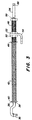
- Two recognizable stops 38, hook parts or the like in FIGS. 2 and 3. are at the Rod 34 provided such that it has a sliding movement of a first disc 40 with respect limit to Fig. 1 to the left.
- a compression spring 42 bears against the first disk 40 is attached to the rod 34.
- a second disc 44 on the rod lies against the other End of the compression spring 42 and is in shape against the compression spring via a threaded part 46 a sleeve with an external thread pushed onto the rod.
- the rod 34 is inside the sleeve is displaceable, whereas the threaded part 46 relative to the mower deck 14 is adjustable, but in use does not change its position with respect to the mower deck 14.
- a screw head is used at one end of the sleeve.
- the tensioning disk 28 is pressed against the belt via the spring and thus gives the belt the belt tension required for normal use.
- the over the pulley 28 Tension applied to the belt supports the belt in that it is always so good Contact with the pulleys has caused the belt to slip during normal use is largely avoided. Likewise, the belt tension causes the belt to not jumps off the pulleys.
- the tensioning pulley 28 is arranged in such a way that it tensions the belt in an area 30 which would be relatively limp otherwise.
- the belt is pulled clockwise over the drive pulley 24. Since the belt is not rigid but flexible, the drive pulley 24 can drive the belt 22 in do not push or push its second area 30. The first section 20 of the belt 22 will therefore held taut by the drive pulley 24 while the second portion 30 of the belt is kept relatively limp. But since the tensioning disk 28 on the relatively limp second section 30 of the belt 20 attacks, only a relatively small force has to be exerted there to overcome the current lack of tension and to create a correct tension.
- the tensioning device 10 exerts a force on the tensioning arm and thus causes the tensioning disk 28 is pressed against the drive belt 22 to be the belt in this area To take off tension and to be able to tension the belt sufficiently.
- the compression spring 42 extends between the two disks 40 and 44 and acts both.
- the second washer 44 is pressed against the threaded part 46, which the first nut 50 against presses the support part 54.
- the support part 54 is with the top of the mower housing firmly connected and is therefore a solid d. H. stationary support against which the compression spring 42 presses.
- the compression spring 42 also acts on the first disk 40, which in turn is remote from the compression spring Side rests against the stops 38 on the rod 34.
- the tensioning device 10 should be set such that the Compression spring 42 between the two disks 40 and 44 is fully compressed.
- the compression spring can cause signs of fatigue that lead to belt elongation then relax or expand accordingly, so that the clamping disk 28 again against the Drive belt 22 is pressed so that it receives its required tension again. That I but on the other hand the compression spring in normal use is always in its block position in which it is is fully compressed, the tensioning device acts for a clockwise movement 1 - in a direction that leads away from the drive belt 22 - as a stop or rigid rod that blocks movement in such a direction.
- a movement in such a direction can occur in itself when a mowing knife hits an obstacle or if the drive pulley is additionally braked against overrun when the engine is switched off becomes.
- the drive belt is loaded with an additional tensioning force wants to adjust the tension arm clockwise with reference to FIG. 1. Such an adjustment will but prevented by the clamping device 10, as will be explained in more detail below.
- the clamping device 10 then acts as a rigid device and blocked a spring washer movement in this direction.
- the tensioning device thus prevents one Adjustment of the tension pulley 28 away from the drive belt and thus a whipping of the belt, resulting in the belt coming loose from the drive pulley or one or all of the pulleys could lead.
- the compression spring is already fully compressed there are no loud noises, especially loud ones, when there are additional voltages Noises on.
- the belt is additionally tensioned when the drive pulley 24 is braked. For safety reasons, this should always be done when the driver leaves the driver's seat on the vehicle for any reason. In such a case the mowing blades are braked immediately as the driver must be prevented from being hit by one the knife can be endangered. If the brake is applied to the drive pulley, then you can the then rotating mower blades or pulleys cause the belt for a receives a driving force for a short time. In such a case, the pulleys 18 tighten the second section 30 of the belt 22, so that the latter in its second section 30 is raised Is exposed to tension. In this case, too, the increased voltage will drive the pulley from their position in Fig.
- a tension is generated by the tensioning device 10 is sufficiently large to keep the drive belt 22 in contact with its pulleys 18, 24 and 28 hold without slippage during normal use. If now a mowing knife against encounters or grazes an obstacle or when the brake hits the drive pulley 24 is applied, then with the compression spring 42 fully compressed, the drive belt 22nd slip with respect to the corresponding pulleys so that the belt and pulleys existing drive system is not damaged.
- the tensioning device 10 tensions the Drive belt 22 such that the friction between the drive belt and the pulleys is large enough to avoid slippage in normal use, and on the other hand not so large is that the belt does not slip when a knife hits an obstacle could.
- the tensioning device 10 can also be adjusted or adjusted by an operator so that the specified preload always prevails.
- a reenactment for example recommended if the drive belt has stretched after a long period of use. In one Fall occurs, which is absorbed by the compression spring 42, which then relaxes somewhat becomes. However, as soon as the compression spring relaxes, there is less pretension on the drive belt exercise as recommended, which is why adjustment of the tensioning device is necessary becomes.
- the two nuts 50 and 52 adjusted on the threaded part 46 such that the threaded part 46 in the opening of the support part 54, the is firmly connected to the mower housing 14, can be adjusted, namely from its position 1 to the left.
- a display is provided on the rod 34, for example in the form of an opening 58, which visibly indicates to the operator when the correct preload has been reached.
- the rod 34 moves relative to the threaded part 46, whereby the position of the display opening is selected such that it is just at the right end of the Part of the thread is visible again when the correct tension on the drive belt has been reached.
- This position is shown in Fig. 3.
- the operator must find the correct preload turn the threaded part until it moves to the left until the display opening is visible again. As soon as the operator sees the opening, they know that they are correct Preload is reached.
- the correct bias can only be achieved in the preferred embodiment if the Compression spring is fully compressed. If the preload is less than recommended, then the display opening 58 is no longer visible, because then the rod 34 in the threaded part left has adjusted. This is possible because when the drive belt stretches, the compression spring in the appropriate amount relaxed, but exerts less force on the belt. Is the preload too small, the tensioning device 10 should be in the manner described above and Be adjusted in a way. However, the adjustment of the threaded part 46 should be stopped immediately, when the display opening 58 becomes visible again.
- the display is used to find the correct bias, after the drive belt 22 has stretched after a longer period of use.
- the pole part 34 serves as a device with which the length of the compression spring 42 can be located. at correct setting, the display opening 58 is just visible at the right end of the threaded part 46.
- the tensioning pulley 28 moves from its position in FIG. 1 to the left. All this is done via the compression spring 42.
- the rod 34 is also adjusted to the left. With reference 3 this means that the display opening 58 is also moved to the left and then in the threaded part 46 disappears or is covered by this, while the support part 54 in its Position remains. As soon as the display opening 58 is no longer visible, the tensioning device should 10 can be adjusted again.
- the compression spring 42 the clamping device is always fully compressed. In the event of vibrations, etc., the spring can expand slightly in the short term. But if the tensioning disk 28 springs back into its starting position, the compression spring is back on block and acts as a backstop that prevents the compression spring from between to jump back and forth in their fully tense and somewhat relaxed position. At least such a movement is dampened. Furthermore, the friction between the compression spring 42 and the rod 34 have a damping effect if belt vibrations occur during use occur.
- An adjustment of the threaded part 46 relative to the support part 54 can also be made by appropriate The nuts 50 and 52 are actuated.
- the nuts may not be necessary if the through hole in the support part 54 is provided with an internal thread.
- the threaded part is then 42 to provide on the tension arm 32.
- the two nuts 50 and 52 would then be similar act as in the embodiment of FIGS. 1 to 3. Also in this case, the compression spring at one normal use fully compressed. It is also possible that the support part is integrated in the mower housing.
Landscapes
- Life Sciences & Earth Sciences (AREA)
- Environmental Sciences (AREA)
- Engineering & Computer Science (AREA)
- General Engineering & Computer Science (AREA)
- Mechanical Engineering (AREA)
- Harvester Elements (AREA)
- Devices For Conveying Motion By Means Of Endless Flexible Members (AREA)
Claims (10)
- Transmission avec mécanisme de traction pour un instrument de travail, en particulier pour une tondeuse à gazon raccordable à un véhicule, avec au moins un mécanisme de traction sans fin (22) pour l'entraínement d'au moins un outil de travail, une poulie de transmission (24), au moins une poulie (18) affectée à un outil de travail et avec une poulie tendeuse (28) qui est prévue sur un bras de serrage (32) qui est logé pour pouvoir pivoter de manière à pouvoir être tendu dans une première direction dans laquelle le mécanisme de traction (22) peut être tendu et à pivoter dans une deuxième direction dans laquelle le mécanisme de traction (22) peut être détendu, et avec un ressort à pression (42) dont la force de rappel agit dans la première direction, caractérisé en ce que le ressort à pression (42) est réglé de telle manière pendant le fonctionnement qu'il bloque un mouvement du bras de serrage (32) au moins essentiellement dans la deuxième direction.
- Transmission avec mécanisme de traction selon la revendication 1, dans lequel un mécanisme bloquant un mouvement du bras de serrage (32) dans la deuxième direction comportent une partie en forme de tige (34) et une partie support (54), caractérisé en ce que le ressort à pression (42) est tenu par la partie en forme de tige (34), en ce qu'il exerce une action antagoniste sur la partie en forme de tige (34) avec l'une de ses extrémités et sur la partie support (54) avec son autre extrémité, la partie en forme de tige (34) s'insérant à une extrémité dans le bras de serrage (32) ou dans l'instrument de travail (capot de tondeuse à gazon 14) et la partie support (54) étant prévue sur l'instrument de travail (capot de tondeuse à gazon 14)ou sur le bras de serrage (32).
- Transmission avec mécanisme de traction selon la revendication 2, caractérisé en ce que la partie en forme de tige (34) peut être déplacée dans la partie support (54).
- Transmission avec mécanisme de traction selon une ou plusieurs des revendications précédentes, caractérisé par une partie filetée (46) qui, à une extrémité, est adjacente au ressort de pression (42), dans laquelle est logée la partie en forme de tige (34) de manière coulissante et qui est reliée avec la partie support (54) de manière orientable.
- Transmission avec mécanisme de traction selon la revendication 4, caractérisé en ce que la partie filetée (46) est formée comme une douille avec un filetage mâle.
- Transmission avec mécanisme de traction selon la revendication 5, caractérisé en ce que la partie filetée (46) peut être vissée dans la partie support (54).
- Transmission avec mécanisme de traction selon la revendication 5, caractérisé en ce que la partie filetée (46) est munie de deux écrous (50, 52) qui peuvent être déplacés sur le filetage et mis en appui de chaque côté de la partie support (54).
- Transmission avec mécanisme de traction selon une ou plusieurs des revendications précédentes, caractérisé en ce que, dans la position du ressort de pression (42) bloquant un mouvement dans la deuxième direction, une indication (58) est visible sur la partie en forme de tige (34).
- Transmission avec mécanisme de traction selon la revendication 1, caractérisé en ce que le ressort de pression (42) est entièrement comprimé dans sa position de blocage d'un mouvement dans la deuxième direction.
- Transmission avec mécanisme de traction selon une ou plusieurs des revendications précédentes, caractérisé en ce que la portion sortant de la partie filetée (46) de la partie en forme de tige (34) est munie d'une butée à son extrémité.
Applications Claiming Priority (2)
| Application Number | Priority Date | Filing Date | Title |
|---|---|---|---|
| US708568 | 1996-09-05 | ||
| US08/708,568 US5769747A (en) | 1996-09-05 | 1996-09-05 | Belt tensioning mechanism with stop feature |
Publications (3)
| Publication Number | Publication Date |
|---|---|
| EP0827683A2 EP0827683A2 (fr) | 1998-03-11 |
| EP0827683A3 EP0827683A3 (fr) | 2000-03-22 |
| EP0827683B1 true EP0827683B1 (fr) | 2002-11-06 |
Family
ID=24846325
Family Applications (1)
| Application Number | Title | Priority Date | Filing Date |
|---|---|---|---|
| EP97114151A Expired - Lifetime EP0827683B1 (fr) | 1996-09-05 | 1997-08-16 | Transmission à courroie pour un instrument de travail |
Country Status (4)
| Country | Link |
|---|---|
| US (1) | US5769747A (fr) |
| EP (1) | EP0827683B1 (fr) |
| CA (1) | CA2200621C (fr) |
| DE (1) | DE59708655D1 (fr) |
Families Citing this family (37)
| Publication number | Priority date | Publication date | Assignee | Title |
|---|---|---|---|---|
| FR2755201B1 (fr) * | 1996-10-25 | 1998-12-04 | Hutchinson Sa | Tendeur pour dispositif mecanique de transmission de puissance, dispositif comportant un tel tendeur et moteur thermique pour vehicule automobile comportant un tel dispositif |
| JP3418136B2 (ja) | 1999-03-17 | 2003-06-16 | 株式会社クボタ | モーア |
| FR2794206B1 (fr) * | 1999-05-26 | 2001-07-06 | Kuhn Sa | Procede de montage/demontage et de reglage automatique de la tension d'un organe de transmission sans fin - machine agricole utilisant un tel procede |
| DE19924574C1 (de) * | 1999-05-28 | 2001-02-01 | Stella Engineering Gmbh | Mähgerät |
| US6312352B1 (en) | 1999-09-10 | 2001-11-06 | Deere & Company | Synchronous belt drive tensioning assembly |
| US6176071B1 (en) | 1999-09-10 | 2001-01-23 | Deere & Company | Tensioning idler assembly for mower deck belt drive |
| GB0102887D0 (en) * | 2001-02-06 | 2001-03-21 | Satake Eng Co Ltd | A flexible drive transmission system |
| US6578349B2 (en) * | 2001-08-07 | 2003-06-17 | Deere & Company | Pivoting gearbox for rotary mower |
| US6602155B2 (en) | 2001-08-07 | 2003-08-05 | Deere & Company | Pivoting idler assembly for belt drive mower |
| WO2004036087A1 (fr) * | 2002-10-14 | 2004-04-29 | Mtd Products Inc | Ensemble d'amortissement de vibrations |
| US7028456B2 (en) * | 2003-07-14 | 2006-04-18 | Shivvers Group, Inc. | Mower with flip up mowing deck |
| US6952913B1 (en) * | 2004-05-13 | 2005-10-11 | Auburn Consolidated Industries, Inc. | Adjustable belt pulley system |
| GB2419650A (en) * | 2004-10-27 | 2006-05-03 | Cnh Belgium Nv | Belt drive for a harvester with a movable cutter |
| US20060183585A1 (en) * | 2005-02-11 | 2006-08-17 | Quantum Corporation | Integrated belt tensioning devices and associated methods |
| US20060230734A1 (en) * | 2005-04-14 | 2006-10-19 | Deere & Company, A Delaware Corporation | Twin belt mule drive |
| US7553248B2 (en) * | 2005-09-21 | 2009-06-30 | Exmark Manufacturing Company, Incorporated | Belt drive system incorporating fixed brake member |
| US7665284B1 (en) | 2007-10-16 | 2010-02-23 | Excel Industries, Inc. | Belt drive for lawn mowers |
| US8060968B2 (en) * | 2008-08-28 | 2011-11-22 | Emerson Electric Co. | Variable belt tensioner for drain cleaning devices |
| JP5596642B2 (ja) * | 2011-08-31 | 2014-09-24 | 株式会社クボタ | 乗用型草刈機 |
| US8539745B2 (en) | 2011-12-06 | 2013-09-24 | The Toro Company | Dual bladed walk power mower with rear bagging mode |
| US9730383B2 (en) * | 2013-03-13 | 2017-08-15 | Husqvarna Ab | Slip controlling belt tension system |
| BE1023230B1 (nl) * | 2015-08-24 | 2017-01-05 | Cnh Industrial Belgium Nv | Spanrolgeheel voor een riemaandrijving |
| CN105179620A (zh) * | 2015-10-22 | 2015-12-23 | 中联重机股份有限公司 | 用于传动带的双张紧装置以及相应的带传动系统 |
| JP6671758B2 (ja) * | 2016-01-20 | 2020-03-25 | ヤンマー株式会社 | 作業車両 |
| CN105830647B (zh) * | 2016-06-06 | 2018-01-30 | 江苏沃得植保机械有限公司 | 随进式割草机割台传动装置 |
| US11758843B2 (en) | 2016-09-29 | 2023-09-19 | Deere & Company | Mower deck belt tensioning arm |
| GB201721786D0 (en) * | 2017-12-22 | 2018-02-07 | Agco Corp | Easy adjust tensioner assembly |
| US11009105B2 (en) * | 2018-01-02 | 2021-05-18 | Agco Corporation | Easy adjust tensioner assembly |
| US20200080622A1 (en) * | 2018-09-11 | 2020-03-12 | Rf Products, Inc. | Mower Deck Drive Belt Displacement Dampening System |
| US11499607B2 (en) * | 2019-04-25 | 2022-11-15 | Johnson Controls Tyco IP Holdings LLP | Drive belt tensioner systems and methods |
| CN110594373B (zh) * | 2019-08-13 | 2024-02-13 | 上海海尔洗涤电器有限公司 | 一种皮带张紧机构、干衣机及干衣机的皮带的张紧方法 |
| US11178815B1 (en) * | 2019-08-19 | 2021-11-23 | Bad Boy Mowers, Llc | Stand-on mower intermediate pulley system |
| US11365788B2 (en) * | 2019-10-31 | 2022-06-21 | Deere & Company | Mower drive belt tensioner arm |
| IT202100018350A1 (it) * | 2021-07-12 | 2023-01-12 | Ma Ri Na Systems S R L | Macchina tosaerba |
| CN114402791A (zh) * | 2021-12-21 | 2022-04-29 | 湖南工艺美术职业学院 | 一种园林景观设计用草坪修剪设备 |
| US20250180099A1 (en) * | 2022-03-07 | 2025-06-05 | Husqvarna Ab | Belt tension adjustment system |
| GB202314571D0 (en) * | 2023-09-22 | 2023-11-08 | Ocado Innovation Ltd | Take-up arm, load handling device and related storage and retreival system |
Family Cites Families (12)
| Publication number | Priority date | Publication date | Assignee | Title |
|---|---|---|---|---|
| US2663195A (en) * | 1950-06-20 | 1953-12-22 | Eaton Mfg Co | Belt tensioner |
| US3365969A (en) * | 1965-06-11 | 1968-01-30 | Int Harvester Co | Transfer pulley tensioning device |
| US3785085A (en) * | 1971-11-18 | 1974-01-15 | G Peroni | Model vehicle for erratic action |
| US3766722A (en) * | 1972-09-18 | 1973-10-23 | Simplicity Mfg Co Inc | Reversing shuttle transmission |
| US4068452A (en) * | 1976-03-11 | 1978-01-17 | Allis-Chalmers Corporation | Mower spindle and spindle drive belt braking arrangement for rotary mower having plurality of mower spindles |
| US4191006A (en) * | 1978-05-08 | 1980-03-04 | International Harvester Company | Floating cutterbar knife drive |
| US4317325A (en) * | 1980-12-18 | 1982-03-02 | J. I. Case Comany | Timing belt adjustment mechanism |
| US4346547A (en) * | 1981-03-27 | 1982-08-31 | Allison Robert B | Lawn mower |
| EP0126808B1 (fr) * | 1983-05-27 | 1988-08-10 | Ford New Holland N.V. | Ensemble de transmission de force à courroie comportant un dispositif tendeur de courroie |
| US4813215A (en) * | 1987-05-07 | 1989-03-21 | Simplicity Manufacturing, Inc. | Mower belt transmission with blade brake |
| GB8902933D0 (en) * | 1989-02-09 | 1989-03-30 | Ransomes Sims & Jefferies Plc | Grass cutting unit |
| US5012632A (en) * | 1990-03-05 | 1991-05-07 | Deere & Company | Belt tensioner |
-
1996
- 1996-09-05 US US08/708,568 patent/US5769747A/en not_active Expired - Lifetime
-
1997
- 1997-03-20 CA CA002200621A patent/CA2200621C/fr not_active Expired - Fee Related
- 1997-08-16 DE DE59708655T patent/DE59708655D1/de not_active Expired - Fee Related
- 1997-08-16 EP EP97114151A patent/EP0827683B1/fr not_active Expired - Lifetime
Also Published As
| Publication number | Publication date |
|---|---|
| CA2200621A1 (fr) | 1998-03-05 |
| CA2200621C (fr) | 2000-06-20 |
| DE59708655D1 (de) | 2002-12-12 |
| EP0827683A3 (fr) | 2000-03-22 |
| EP0827683A2 (fr) | 1998-03-11 |
| US5769747A (en) | 1998-06-23 |
Similar Documents
| Publication | Publication Date | Title |
|---|---|---|
| EP0827683A2 (fr) | Transmission à courroie pour un instrument de travail | |
| EP0445623B1 (fr) | Transmission à courroie pour un instrument de travail, en particulier pour une tondeuse à gazon connectée à un véhicule | |
| EP1082893B1 (fr) | Faucheuse et véhicule ou appareil | |
| DE3784509T2 (de) | Rasenmaehvorrichtung. | |
| EP0933013B1 (fr) | Mécanisme de réglage et unité de coupe | |
| DE19901453B4 (de) | Trimmaschine mit einer Bremseinrichtung für das Schneidblatt | |
| DE60007796T2 (de) | Riemenspannvorrichtung | |
| EP1072184A1 (fr) | Dispositif d'actionnement pour une unité de traitement ou transport de la récolte dans un tablier d'une moissonneuse-batteuse | |
| EP0036198A1 (fr) | Transmission à courroie embrayable | |
| EP1101976A2 (fr) | Dispositif de tension, système de transmission à élément flexible et véhicule | |
| DE2521474B2 (de) | Spann- und reibungsschweissvorrichtung fuer ein einen gegenstand umschlingendes band aus thermoplastischem kunststoff | |
| DE60300438T2 (de) | Arbeitsmaschine und zugehörige umkehrbare Zuführungseinrichtungen | |
| EP1082892B1 (fr) | Faucheuse et véhicule ou appareil | |
| EP1284374B1 (fr) | Dispositif de tension et machine de travail, particulièrement une tondeuse à gazon | |
| EP1245141B1 (fr) | Appareil de travail à unités de travail pivotables | |
| DE2927334A1 (de) | Schneidvorrichtung fuer landwirtschaftliche erntemaschinen | |
| DE2412911A1 (de) | Drehmomentbegrenzungsvorrichtung und damit ausgeruestete erntemaschine | |
| DE60309917T2 (de) | Schwingungsdämpfungsanordnung | |
| DE602005006069T2 (de) | Riemenspanneinrichtung | |
| EP0095690A1 (fr) | Presse à balles rondes dont la chambre de compactage comprend une entrée pour le matériau | |
| DE3729625C1 (de) | Fahrbares Maehgeraet,insbesondere fuer land- und forstwirtschaftliche Zwecke | |
| DE1816643A1 (de) | Verstellbare Haspel fuer Erntemaschinen,insbesondere selbstmaehende Presszetter | |
| DE3504602C1 (de) | Fahrbares Rasenpflegegerät mit einem Antriebsmotor für das Pflegewerkzeug und den Fahrantrieb | |
| DE69900324T2 (de) | Verteilmaschine | |
| DE102007019155B4 (de) | Aufsitzrasenmäher mit Mähdeck |
Legal Events
| Date | Code | Title | Description |
|---|---|---|---|
| PUAI | Public reference made under article 153(3) epc to a published international application that has entered the european phase |
Free format text: ORIGINAL CODE: 0009012 |
|
| AK | Designated contracting states |
Kind code of ref document: A2 Designated state(s): DE FR GB IT |
|
| AX | Request for extension of the european patent |
Free format text: AL;LT;LV;RO;SI |
|
| PUAL | Search report despatched |
Free format text: ORIGINAL CODE: 0009013 |
|
| AK | Designated contracting states |
Kind code of ref document: A3 Designated state(s): AT BE CH DE DK ES FI FR GB GR IE IT LI LU MC NL PT SE |
|
| AX | Request for extension of the european patent |
Free format text: AL;LT;LV;RO;SI |
|
| RIC1 | Information provided on ipc code assigned before grant |
Free format text: 7A 01D 34/68 A, 7F 16H 7/12 B, 7A 01D 34/76 B |
|
| 17P | Request for examination filed |
Effective date: 20000427 |
|
| AKX | Designation fees paid |
Free format text: DE FR GB IT |
|
| 17Q | First examination report despatched |
Effective date: 20010313 |
|
| GRAG | Despatch of communication of intention to grant |
Free format text: ORIGINAL CODE: EPIDOS AGRA |
|
| GRAG | Despatch of communication of intention to grant |
Free format text: ORIGINAL CODE: EPIDOS AGRA |
|
| GRAG | Despatch of communication of intention to grant |
Free format text: ORIGINAL CODE: EPIDOS AGRA |
|
| GRAH | Despatch of communication of intention to grant a patent |
Free format text: ORIGINAL CODE: EPIDOS IGRA |
|
| RAP1 | Party data changed (applicant data changed or rights of an application transferred) |
Owner name: DEERE & COMPANY |
|
| GRAH | Despatch of communication of intention to grant a patent |
Free format text: ORIGINAL CODE: EPIDOS IGRA |
|
| GRAA | (expected) grant |
Free format text: ORIGINAL CODE: 0009210 |
|
| AK | Designated contracting states |
Kind code of ref document: B1 Designated state(s): DE FR GB IT |
|
| REG | Reference to a national code |
Ref country code: GB Ref legal event code: FG4D Free format text: NOT ENGLISH |
|
| REF | Corresponds to: |
Ref document number: 59708655 Country of ref document: DE Date of ref document: 20021212 |
|
| GBT | Gb: translation of ep patent filed (gb section 77(6)(a)/1977) |
Effective date: 20030121 |
|
| ET | Fr: translation filed | ||
| PLBE | No opposition filed within time limit |
Free format text: ORIGINAL CODE: 0009261 |
|
| STAA | Information on the status of an ep patent application or granted ep patent |
Free format text: STATUS: NO OPPOSITION FILED WITHIN TIME LIMIT |
|
| 26N | No opposition filed |
Effective date: 20030807 |
|
| PGFP | Annual fee paid to national office [announced via postgrant information from national office to epo] |
Ref country code: IT Payment date: 20060831 Year of fee payment: 10 |
|
| PGFP | Annual fee paid to national office [announced via postgrant information from national office to epo] |
Ref country code: DE Payment date: 20080721 Year of fee payment: 12 |
|
| PGFP | Annual fee paid to national office [announced via postgrant information from national office to epo] |
Ref country code: FR Payment date: 20080818 Year of fee payment: 12 |
|
| PG25 | Lapsed in a contracting state [announced via postgrant information from national office to epo] |
Ref country code: IT Free format text: LAPSE BECAUSE OF NON-PAYMENT OF DUE FEES Effective date: 20070816 |
|
| REG | Reference to a national code |
Ref country code: FR Ref legal event code: ST Effective date: 20100430 |
|
| PG25 | Lapsed in a contracting state [announced via postgrant information from national office to epo] |
Ref country code: FR Free format text: LAPSE BECAUSE OF NON-PAYMENT OF DUE FEES Effective date: 20090831 Ref country code: DE Free format text: LAPSE BECAUSE OF NON-PAYMENT OF DUE FEES Effective date: 20100302 |
|
| PGFP | Annual fee paid to national office [announced via postgrant information from national office to epo] |
Ref country code: GB Payment date: 20130827 Year of fee payment: 17 |
|
| GBPC | Gb: european patent ceased through non-payment of renewal fee |
Effective date: 20140816 |
|
| PG25 | Lapsed in a contracting state [announced via postgrant information from national office to epo] |
Ref country code: GB Free format text: LAPSE BECAUSE OF NON-PAYMENT OF DUE FEES Effective date: 20140816 |