EP0827700A1 - Sportschuh mit einer Vorrichtung zum Sperren einer Schwenkbewegung des Schaftes - Google Patents
Sportschuh mit einer Vorrichtung zum Sperren einer Schwenkbewegung des Schaftes Download PDFInfo
- Publication number
- EP0827700A1 EP0827700A1 EP97113364A EP97113364A EP0827700A1 EP 0827700 A1 EP0827700 A1 EP 0827700A1 EP 97113364 A EP97113364 A EP 97113364A EP 97113364 A EP97113364 A EP 97113364A EP 0827700 A1 EP0827700 A1 EP 0827700A1
- Authority
- EP
- European Patent Office
- Prior art keywords
- rod
- cam
- immobilization
- zone
- rotary cam
- Prior art date
- Legal status (The legal status is an assumption and is not a legal conclusion. Google has not performed a legal analysis and makes no representation as to the accuracy of the status listed.)
- Ceased
Links
- 230000005489 elastic deformation Effects 0.000 claims description 3
- 238000012423 maintenance Methods 0.000 claims description 3
- 210000003423 ankle Anatomy 0.000 abstract description 5
- 238000005452 bending Methods 0.000 description 14
- 238000010276 construction Methods 0.000 description 8
- 230000003100 immobilizing effect Effects 0.000 description 7
- 230000000903 blocking effect Effects 0.000 description 4
- 238000006073 displacement reaction Methods 0.000 description 3
- 230000000694 effects Effects 0.000 description 2
- 235000005921 Cynara humilis Nutrition 0.000 description 1
- 240000002228 Cynara humilis Species 0.000 description 1
- 241000909536 Gobiesocidae Species 0.000 description 1
- 210000004027 cell Anatomy 0.000 description 1
- 238000013016 damping Methods 0.000 description 1
- 230000002349 favourable effect Effects 0.000 description 1
- 238000000034 method Methods 0.000 description 1
- 230000000750 progressive effect Effects 0.000 description 1
- 230000004043 responsiveness Effects 0.000 description 1
Images


Classifications
-
- A—HUMAN NECESSITIES
- A43—FOOTWEAR
- A43B—CHARACTERISTIC FEATURES OF FOOTWEAR; PARTS OF FOOTWEAR
- A43B5/00—Footwear for sporting purposes
- A43B5/04—Ski or like boots
- A43B5/0427—Ski or like boots characterised by type or construction details
- A43B5/0452—Adjustment of the forward inclination of the boot leg
- A43B5/0454—Adjustment of the forward inclination of the boot leg including flex control; Dampening means
- A43B5/0456—Adjustment of the forward inclination of the boot leg including flex control; Dampening means with the actuator being disposed at the rear side of the boot
-
- A—HUMAN NECESSITIES
- A43—FOOTWEAR
- A43B—CHARACTERISTIC FEATURES OF FOOTWEAR; PARTS OF FOOTWEAR
- A43B5/00—Footwear for sporting purposes
- A43B5/04—Ski or like boots
- A43B5/0427—Ski or like boots characterised by type or construction details
- A43B5/047—Ski or like boots characterised by type or construction details provided with means to improve walking with the skiboot
- A43B5/0474—Ski or like boots characterised by type or construction details provided with means to improve walking with the skiboot having a walk/ski position
Definitions
- the present invention relates to a so-called "rigid shell” sports shoe having a base of shell surmounted by a rod capable of pivoting in both directions, antero-posterior and postero-anterior, and relates to an immobilization device with respect to the active shell base for both directions of pivoting of the rod by means of a rotary actuator situated on the latter, and relates in particular to an adjustable immobilization device intended to modify the capacity of bending of the upper in at least one direction, depending on the use of the shoe envisaged at a time.
- the device for immobilizing the rod relative to the shell base is active for one at less of its pivoting directions via a stop zone obtained on the hull base.
- the device is provided with a rotary operating member provided with a rotary cam which acts on a movable element intended, for a given angular position of the cam, to cooperate with the zone abutment of the shell base, and for another given position of the cam, to disengage from said stop zone.
- the movable member cooperates with the abutment area of the shell base, the upper of the shoe is systematically blocked towards the rear, i.e.
- the immobilization device described can therefore modify the ability to pivot the rod between a ski practice position, with or without forward bending ability according to the predetermined construction, and an on-rebound position where the rod is free to pivot.
- Such an immobilization device is satisfactory if the user sticks to the only flexural capacity. forward of the rod which is determined in advance.
- forward of the rod which is determined in advance.
- An object of the present invention is to overcome this drawback of the sports shoes described above, and for this purpose proposes a device for immobilizing the upper of a sports shoe which either suitable for a given angular position of a rotary cam controlled by means of a rotary maneuver, to immobilize the upper of the shoe in the postero-anterior direction in order to skiing while simultaneously providing said rod with a certain bending capacity in the direction postero-anterior before blocking, and, for another given angular position of the cam, always guaranteeing the immobilization of the rod in the antero-anterior direction, by providing at the same time as the rod, another capacity for bending or even eliminating the latter.
- the invention provides, for a position of constant immobilization of the rod in the anteroposterior direction, two possible immobilization positions in the postero-anterior direction determining two different flexural capacities of said rod.
- Another object of the invention is to allow the release of the rod in pivoting in the direction antero-posterior in view, for example, of facilitating walking or putting on and taking off, in bringing the rotary cam into at least one intermediate angular position situated between the positions previous angular immobilization of the rod, and this leaving the rod a certain capacity to flexion in the postero-anterior direction.
- the rigid shell sports shoe has, as in the state of the technique constituted by document EP 521 282, a shell base surmounted by a rod capable of pivot in both directions, antero-posterior and postero-anterior, the rod being provided in its zone dorsal, of an immobilization device with respect to the active shell base for at least one of its pivoting direction, via a stop zone obtained on said shell base.
- the immobilizer is provided with an operating member provided with a rotary cam which acts on a movable element intended to cooperate, for a given angular position of the cam, with the area of hull base stop.
- the sports shoe is characterized by the fact that the immobilization device comprises a second mobile element which is actuable by means of the rotary cam and which is intended for cooperate with a second stop zone obtained on the shell base for at least one position given angularity of the cam.
- the cooperation of this second mobile element with this second zone stop is intended to provide immobilization of the rod for one of its two directions of pivoting, while the cooperation of the first movable element with the first stop zone provides immobilization of the rod for the other of its two directions of pivoting.
- the simultaneous implementation of the two movable elements with the two stop zones causes thus immobilizing the upper of the shoe in both directions of pivoting and implementing of a single mobile element with its stop zone only causes the immobilization of the rod in a pivoting direction.
- the simultaneous disengagement, or retraction, of the two elements moving causes the rod to be released in both directions of pivoting, while the disengagement of one of the movable elements only causes the release of the rod in a direction of pivoting.
- the rotary cam of the immobilization device is constituted by a plate which, centered on the operating member, comprises at least one circular probing surface having a high working area and a low working area, and the two movable elements of the device cooperate with this feeler surface by means of a feeler member of which they are provided respectively.
- the feelers of the mobile elements come into contact of the probing surface of the cam at a distance from each other, each on one of the working zones high and low, at opposite points relative to the axis of rotation of the operating member.
- the plate constituting the rotary cam has two probing surfaces, one on each side, parallel to each other, and having, each, a high work area and a low work area, each moving element coming cooperate with one of the two probing surfaces by means of its probing member.
- the plate constituting the cam rotary has a single probing surface having, on 360 °, two bosses in the form of arcs of circle of the same height and different lengths defining between them two slots which their are symmetrically opposite with respect to the axis of rotation of the cam and therefore of the maneuver, the bosses constituting the upper work area and the slots the work area low.
- the two abutment zones of the shell base are obtained and located in the heel part thereof, each stop zone being intended to ensure, in cooperation with one of the two movable elements of the immobilizer and for at least one given angular position of the rotary cam, immobilization of the rod in one of its directions pivoting.
- the two abutment zones of the shell base are formed, one by a vertical notch open upwards and delimited by flexible edges for its porto-anterior immobilization, and the other by its shoulder for its antero-posterior immobilization.
- the abutment zone formed by the notch is located above that formed by the shoulder. It is covered by the dorsal area of the stem and is intended for cooperate with one of the movable elements which can, as desired, under the action of the rotary cam and for determined angular positions thereof, to retract from said notch or to be inserted between its flexible edges thereby providing a certain possibility of postero-anterior pivoting of the rod or its immobilization in this direction.
- the flexible edges of the latter can be bring them closer to each other by elastic deformation under the pushing effect of the dorsal area of the rod which covers it and which describes an engaging trajectory on the heel part of the hull base to the place of said notch.
- the notch thus constitutes the abutment zone of the shell base capable of immobilizing the rod in the postero-anterior direction, and, depending on the angular position given to the rotary cam by means of the operating member, the abutment zone also capable of authorizing some possibility of bending of the rod in the postero-anterior direction.
- the shoulder constituting the second stop zone is located below and transversely to the latter, also on the heel part of the shell base, and it is the second movable element of the immobilization device, that is to say the one not associated functionally with the notch, which is intended to cooperate with.
- this movable element bears on the shoulder under the action of the rotary cam, for a position angular given thereof, and in particular when the rod is urged to bend in the antero-posterior direction.
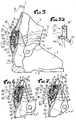
- the shoe 1 designated overall, and shown in Figures 1 to 3 is of the "front entry" type.
- This shoe 1 consists of a so-called rigid shell having a shell base 2 provided a sole 6, and surmounted by a rod 3 capable of pivoting thereon in the anteroposterior direction indicated by arrow 20, and postero-anterior indicated by arrow 21, by rotation around lateral connections 4, 4 ', preferably located in correspondence with the articulation of the wearer's ankle, not represented.
- An immobilizer 10 located on the dorsal area 5 of the rod 3 is provided with a rotary actuator 11, accessible from the outside of the boot shell, to which two movable elements 12, 13, are subject to displacement by means of a rotary cam (not represented) with which it is provided.
- Two abutment zones 14 and 15 are obtained in the heel part 16 of the shell base 2 in correspondence of the movable elements 12, 13, of the immobilization device 10. In this way, these elements 12, 13, can come to cooperate, after a displacement generated by the rotary cam, with the abutment zones 14 and 15 for at least one given angular position of the rotary cam, i.e. the operating member 11 which is provided with it.
- These abutment zones 14 and 15 are oriented so as to oppose the pivoting of the rod 3 in the antero-posterior 20 and / or postero-anterior direction 21, when the element 12 and / or 13 cooperates with.
- the rod 3 is then free to pivot with a certain amplitude, in the two posterior-anterior 21 and antero-posterior directions 20, around its connections 4, 4 ', with respect to the shell base 2.
- the shoe 1 is with a great flexibility of upper 3 which is favorable for facilitating walking and / or putting on and taking off for example.
- the abutment zone 14, covered by the dorsal zone 5 of the rod 3 is constituted by a vertical notch obtained in the heel part 16 of the shell base 2.
- This vertical notch 14, open upwards, is delimited by flexible edges 14 '.
- These are intended to reciprocally approach each other by elastic deformation, as indicated by the arrows 22, under the pushing effect of the dorsal zone 5 of the rod 3, when the said rod 3 pivots in the postero-anterior direction 21 around its connections 4, 4 ′, and when the movable element 12 is not inserted between them; it is understood that the force applied to the rod 3 must be greater than the resistant one opposed by the flexible edges 14 'to obtain a some bending.
- Lateral cutouts 17, 17 ′ can optionally be made in the base of shell 2, relatively in front of the heel part 16 thereof, in order to reduce the resistance to bending of the edges 14 ′ of the notch and therefore giving the upper 3 of the shoe a certain flexibility in the anteroposterior direction which is possible under low effort. It's obvious that the extent and shape of such lateral cutouts 17, 17 ', are provided by construction, during the definition of the structure of the hull base 2, as a function of the initial damping desired at rod level 3.
- the second stop zone 15 is located below and is presented in the form of a transverse shoulder approximately perpendicular to the notch 14.
- the second movable element 13 of the immobilizing device 10 is intended to cooperate with this shoulder 15 by bearing on it under the action of the rotary cam (not shown) of the immobilizer 10 only when the rod 3 is urged to pivot in the antero-posterior direction 20.
- FIG. 5 figure 1
- figure 6 figure 2
- figure 7 figure 3.
- the cam rotary 30 consists of a plate comprising, on each face, a probing surface 31, 32, as shown in Figure 5a. These probing surfaces 31 and 32 are mutually parallel and each have a 360 ° upper work area 33 and a lower work area 34. so, the upper 33 and lower 34 work zones are located, angularly with respect to the axis of rotation 30 '( Figure 5a) of the rotary cam 30, in the same place.
- the passage from a high work area 33 to a low work area 34 is achieved by means of a ramp progressive and angularly extends over approximately 90 °.
- the movable elements 12, 13, are each provided with a feeler 12 ', 13', and are subjected to the action of a spring 18 ensuring their permanent maintenance in contact with said surfaces 31 and 32.
- the mobile element 12 is pivotally mounted on an axis 19 passing through a part of the dorsal zone 5 of the rod 3 near the abutment zone 15, and the element mobile 12 is slidably mounted in a guide 22 obtained in said zone 5 in correspondence with the abutment zone 14 of the shell base 2.
- each 90 ° rotation of the cam 30 by means of the operation 11 causes the displacement of at least one of the movable elements 12 and 13 relative to a stop zone 14 or 15, and intrinsically modifies the immobilization and / or pivoting conditions of the rod 3 relative to the shell base 2.
- the two mobile elements 12 and 13 are used on the stop zones 14 and 15 by means of the rotary cam 30 which is placed in a position angular given allowing them to cooperate with said zones 14 and 15. More specifically, the member probing 12 ′ of the movable element 12 is in contact with the upper working area 33 of the surface of probing 32 of the cam 30 and the probing member 13 'of the movable element 13 is in contact with the area working position 34 of the probing surface 31 of the cam 30. In this position for adjusting the immobilization device 10, the rod 3 is therefore immobilized in pivoting around its connections 4, 4 ', relative to the shell base 2, whether in the antero-posterior 20 or postero-anterior direction 21.
- the upper 3 of the shoe is therefore always prevented from pivot in the antero-posterior direction 20 but able to flex in the antero-posterior direction 21 when an effort applied to it in this direction is sufficient to overcome resistance to deformation opposed to it by the flexible edges 14 ′ of the notch 14.
- the upper 3 of the shoe is then free to pivot in both directions, anteroposterior 20 and posterior anterior 21, it being understood that for bend in the direction 21 the force applied to it must be at least greater than that, resistant, than it oppose the flexible edges 14 ′ of the notch 40 on which the dorsal zone 5 of said lean rod 3.
- the plate 40 constituting the rotary cam comprises a single probing surface 41 circular having, on 360 °, two bosses 42 and 43, and the two movable elements 12, 13, are each rocker mounted on an axis 19.
- These bosses 42 and 43 in the form of arcs of a circle are provided. of the same height and different lengths, and define between them slots 44 and 45 which are symmetrically opposite with respect to the axis of rotation 40 ′ of the cam 40.
- the bosses 42 and 43 constitute the upper work area, and the slots 44 and 45 the low work area.
- the bosses 42, 43, and the slots 44, 45 are also spaced apart.
- FIGS. 8 and 8a show the immobilization device 10 in a position adjustment where the rotary cam 40 has the two slots 44 and 45, which constitute its area of low work, in cooperation with the feelers 12 ′, 13 ′, mobile elements 12 and 13.
- FIGS. 10 and 10a for another given angular position of the cam 40, these are the two bosses 42 and 43, which constitute the upper working area, which cooperate with the probing members 12 ', 13, mobile elements 12 and 13.
- Figures 9 and 9a show the cooperation a boss 43 and a slot 45 with the feelers 12 'and 13' of the movable elements 12 and 13 for yet another given angular position of the cam 40.
- FIG. 8 illustrates the immobilizer 10 in the adjustment positions which correspond to those described respectively with reference to Figures 1, 2 and 3 above.
- the upper 3 of the shoe is immobilized in both directions of pivoting 20 and 21 relative to the shell base, in FIG. 9 in the anteroposterior direction 20 only with a release in the opposite direction 21, and in FIG. 10 with a release in its two directions of pivoting 20 and 21.
- the cam 40 can be brought into an angular position where the boss 43 cooperates with the probing 13 'of element 13, and the slot 45 with the probing member 12' of element 12.
- the rod 3 is released in pivoting in the anteroposterior direction 20, and remains prevented from pivoting in the postero-anterior direction 20.
- the movable elements 12, 13, can either be provided rocked or sliding, and kept in contact with the feeler surface 31, 32, 41, of the rotary cam 30, 40, by means of a spring 18 or by any other equivalent element.
- the stop zones 14 and 15 can easily be produced by the simple arrangement of a notch 14 which is used the bottom to constitute the abutment zone 15 as shown in FIGS. 8 to 10.
Landscapes
- Health & Medical Sciences (AREA)
- General Health & Medical Sciences (AREA)
- Physical Education & Sports Medicine (AREA)
- Footwear And Its Accessory, Manufacturing Method And Apparatuses (AREA)
Applications Claiming Priority (2)
| Application Number | Priority Date | Filing Date | Title |
|---|---|---|---|
| FR9610873A FR2752684B1 (fr) | 1996-09-04 | 1996-09-04 | Chaussure de sport munie d'un dispositif d'immobilisation en pivotement de la tige |
| FR9610873 | 1996-09-04 |
Publications (1)
| Publication Number | Publication Date |
|---|---|
| EP0827700A1 true EP0827700A1 (de) | 1998-03-11 |
Family
ID=9495503
Family Applications (1)
| Application Number | Title | Priority Date | Filing Date |
|---|---|---|---|
| EP97113364A Ceased EP0827700A1 (de) | 1996-09-04 | 1997-08-02 | Sportschuh mit einer Vorrichtung zum Sperren einer Schwenkbewegung des Schaftes |
Country Status (4)
| Country | Link |
|---|---|
| US (1) | US5857271A (de) |
| EP (1) | EP0827700A1 (de) |
| JP (1) | JPH1085001A (de) |
| FR (1) | FR2752684B1 (de) |
Cited By (3)
| Publication number | Priority date | Publication date | Assignee | Title |
|---|---|---|---|---|
| EP2898788A1 (de) * | 2014-01-24 | 2015-07-29 | Salomon S.A.S. | Sportschuh |
| US9241532B2 (en) | 2012-01-04 | 2016-01-26 | K-2 Corporation | Ski/walk mechanism |
| IT202000000988A1 (it) * | 2020-01-20 | 2021-07-20 | Tecnica Group Spa | Scarpone da sci, in particolare scarpone da sci alpinismo |
Families Citing this family (11)
| Publication number | Priority date | Publication date | Assignee | Title |
|---|---|---|---|---|
| US6231066B1 (en) | 1999-03-03 | 2001-05-15 | Shimano Inc. | Active highback system for a snowboard boot |
| FR2793391B1 (fr) * | 1999-05-12 | 2001-06-08 | Salomon Sa | Chaussure de ski de fond |
| FR2819692B1 (fr) * | 2001-01-24 | 2003-05-02 | Salomon Sa | Chaussure de sport, notamment de ski, munie d'un dispositif automatique d'immobilisation en pivotement de la tige |
| FR2924904B1 (fr) * | 2007-12-14 | 2010-01-01 | Salomon Sa | Chaussure de sport avec dispositif de blocage |
| AT512080B1 (de) * | 2011-11-02 | 2013-07-15 | Fischer Sports Gmbh | Skischuh |
| ES2906567T3 (es) | 2015-05-06 | 2022-04-19 | Ober Alp Spa | Bota de esquí provista de un mecanismo de selección de esquí-marcha mejorado |
| CA197133S (en) | 2020-07-27 | 2022-05-12 | Dentec Safety Specialists Inc | Mid-sole traction device |
| CA197134S (en) | 2020-07-27 | 2022-05-12 | Dentec Safety Specialists Inc | Heel traction device |
| CA3088637A1 (en) | 2020-07-31 | 2022-01-31 | Dentec Safety Specialists Inc. | Heel traction device |
| CA3088629A1 (en) | 2020-07-31 | 2022-01-31 | Dentec Safety Specialists Inc. | Mid-sole traction device |
| CA205138S (en) | 2021-07-23 | 2023-03-01 | Dentec Safety Specialists Inc | Heel traction device |
Citations (3)
| Publication number | Priority date | Publication date | Assignee | Title |
|---|---|---|---|---|
| EP0521283A1 (de) * | 1991-07-01 | 1993-01-07 | Salomon S.A. | Schischuh mit Schaftverriegelungsvorrichtung |
| EP0521282A1 (de) * | 1991-07-01 | 1993-01-07 | Salomon S.A. | Skischuh mit Schwenksperre für den Schaft |
| EP0582803A1 (de) * | 1992-08-11 | 1994-02-16 | Salomon S.A. | Schischuh |
-
1996
- 1996-09-04 FR FR9610873A patent/FR2752684B1/fr not_active Expired - Fee Related
-
1997
- 1997-08-02 EP EP97113364A patent/EP0827700A1/de not_active Ceased
- 1997-09-03 US US08/922,361 patent/US5857271A/en not_active Expired - Fee Related
- 1997-09-04 JP JP9239561A patent/JPH1085001A/ja active Pending
Patent Citations (3)
| Publication number | Priority date | Publication date | Assignee | Title |
|---|---|---|---|---|
| EP0521283A1 (de) * | 1991-07-01 | 1993-01-07 | Salomon S.A. | Schischuh mit Schaftverriegelungsvorrichtung |
| EP0521282A1 (de) * | 1991-07-01 | 1993-01-07 | Salomon S.A. | Skischuh mit Schwenksperre für den Schaft |
| EP0582803A1 (de) * | 1992-08-11 | 1994-02-16 | Salomon S.A. | Schischuh |
Cited By (5)
| Publication number | Priority date | Publication date | Assignee | Title |
|---|---|---|---|---|
| US9241532B2 (en) | 2012-01-04 | 2016-01-26 | K-2 Corporation | Ski/walk mechanism |
| EP2898788A1 (de) * | 2014-01-24 | 2015-07-29 | Salomon S.A.S. | Sportschuh |
| FR3016775A1 (fr) * | 2014-01-24 | 2015-07-31 | Salomon Sas | Chaussure de sport |
| IT202000000988A1 (it) * | 2020-01-20 | 2021-07-20 | Tecnica Group Spa | Scarpone da sci, in particolare scarpone da sci alpinismo |
| EP3850978A1 (de) * | 2020-01-20 | 2021-07-21 | Tecnica Group S.p.A. | Skischuh, insbesondere skitourenschuh |
Also Published As
| Publication number | Publication date |
|---|---|
| FR2752684A1 (fr) | 1998-03-06 |
| US5857271A (en) | 1999-01-12 |
| FR2752684B1 (fr) | 1998-10-30 |
| JPH1085001A (ja) | 1998-04-07 |
Similar Documents
| Publication | Publication Date | Title |
|---|---|---|
| EP0827700A1 (de) | Sportschuh mit einer Vorrichtung zum Sperren einer Schwenkbewegung des Schaftes | |
| EP0679416A1 (de) | Vorrichtung zum Befestigen eines Schuhs an einem Gleitorgan | |
| FR2471795A1 (fr) | Butee-avant de fixation de ski | |
| EP0804949A1 (de) | Haltevorrichtung für einen Schuh auf einem Snowboard | |
| WO1996032992A1 (fr) | Fixation de securite pour le ski de telemark, la randonnee nordique et le saut a ski | |
| EP0913102B1 (de) | Sohle für Sportschuh | |
| FR2642980A1 (fr) | Dispositif de fixation pour ski de fond et chaussure destinee a un tel dispositif de fixation | |
| EP1108450B1 (de) | Vorrichtung zur Halterung eines Schuhs auf einem Gleitbrett | |
| EP0726036B1 (de) | Schuh mit kontrollierter Flexibilität | |
| CA2221887A1 (fr) | Dispositif de retenue d'une chaussure sur une planche de glisse destinee a la pratique du surf sur la neige | |
| FR2745474A1 (fr) | Chaussure de sport | |
| EP1104251B1 (de) | Langlaufskischuh | |
| WO1991009654A1 (fr) | Dispositif d'appui, sur un ski, de la partie anterieure de la semelle d'une chaussure | |
| CH673776A5 (de) | ||
| EP3741436B1 (de) | Bindungsvorrichtung zur befestigung eines snowboardschuhs auf einem snowboard | |
| FR2497110A1 (fr) | Machoire avant pour une fixation de securite pour ski | |
| EP0648439B1 (de) | Schischuh | |
| EP0820789B1 (de) | Schuh-Ski Kombination | |
| WO1991008807A1 (fr) | Fixation de securite de ski alpin | |
| EP0692203A1 (de) | Sportschuh, insbesondere Schischuh | |
| EP0436444B1 (de) | Skischuh aus Kunststoff | |
| EP2959949B1 (de) | Vorrichtung zur aufnahme eines schuhs auf einem gleitgerät | |
| EP0823222A1 (de) | Sportschuh | |
| EP0667174A1 (de) | Sicherheitsbindung für Skier mit Ausgleichsvorrichtung | |
| FR2707511A1 (fr) | Dispositif visant à modifier la répartition naturelle d'un ski sur sa surface de glisse, et ski équipé d'un tel dispositif. |
Legal Events
| Date | Code | Title | Description |
|---|---|---|---|
| PUAI | Public reference made under article 153(3) epc to a published international application that has entered the european phase |
Free format text: ORIGINAL CODE: 0009012 |
|
| AK | Designated contracting states |
Kind code of ref document: A1 Designated state(s): AT CH DE FR IT LI |
|
| 17P | Request for examination filed |
Effective date: 19980907 |
|
| AKX | Designation fees paid |
Free format text: AT CH DE FR IT LI |
|
| RBV | Designated contracting states (corrected) |
Designated state(s): AT CH DE FR IT LI |
|
| GRAG | Despatch of communication of intention to grant |
Free format text: ORIGINAL CODE: EPIDOS AGRA |
|
| 17Q | First examination report despatched |
Effective date: 20010612 |
|
| STAA | Information on the status of an ep patent application or granted ep patent |
Free format text: STATUS: THE APPLICATION HAS BEEN REFUSED |
|
| 18R | Application refused |
Effective date: 20020212 |