EP0828060A2 - Procédé de fabrication d'un poussoir de moteur à combustion interne - Google Patents
Procédé de fabrication d'un poussoir de moteur à combustion interne Download PDFInfo
- Publication number
- EP0828060A2 EP0828060A2 EP97115097A EP97115097A EP0828060A2 EP 0828060 A2 EP0828060 A2 EP 0828060A2 EP 97115097 A EP97115097 A EP 97115097A EP 97115097 A EP97115097 A EP 97115097A EP 0828060 A2 EP0828060 A2 EP 0828060A2
- Authority
- EP
- European Patent Office
- Prior art keywords
- tappet body
- spiral groove
- tappet
- outer circumferential
- circumferential surface
- Prior art date
- Legal status (The legal status is an assumption and is not a legal conclusion. Google has not performed a legal analysis and makes no representation as to the accuracy of the status listed.)
- Granted
Links
- 238000002485 combustion reaction Methods 0.000 title claims abstract description 8
- 238000000034 method Methods 0.000 title claims description 20
- 239000011247 coating layer Substances 0.000 claims abstract description 30
- 238000005520 cutting process Methods 0.000 claims abstract description 22
- 229910000838 Al alloy Inorganic materials 0.000 claims abstract description 7
- 230000003247 decreasing effect Effects 0.000 claims abstract description 7
- 239000000463 material Substances 0.000 claims description 13
- 230000007423 decrease Effects 0.000 claims description 4
- 239000011295 pitch Substances 0.000 description 5
- 238000007751 thermal spraying Methods 0.000 description 5
- 238000005422 blasting Methods 0.000 description 3
- 238000005507 spraying Methods 0.000 description 3
- 238000004381 surface treatment Methods 0.000 description 2
- 229910000640 Fe alloy Inorganic materials 0.000 description 1
- 229910001069 Ti alloy Inorganic materials 0.000 description 1
- 238000004519 manufacturing process Methods 0.000 description 1
- 238000012986 modification Methods 0.000 description 1
- 230000004048 modification Effects 0.000 description 1
- 238000007747 plating Methods 0.000 description 1
Images



Classifications
-
- B—PERFORMING OPERATIONS; TRANSPORTING
- B23—MACHINE TOOLS; METAL-WORKING NOT OTHERWISE PROVIDED FOR
- B23P—METAL-WORKING NOT OTHERWISE PROVIDED FOR; COMBINED OPERATIONS; UNIVERSAL MACHINE TOOLS
- B23P15/00—Making specific metal objects by operations not covered by a single other subclass or a group in this subclass
-
- F—MECHANICAL ENGINEERING; LIGHTING; HEATING; WEAPONS; BLASTING
- F01—MACHINES OR ENGINES IN GENERAL; ENGINE PLANTS IN GENERAL; STEAM ENGINES
- F01L—CYCLICALLY OPERATING VALVES FOR MACHINES OR ENGINES
- F01L1/00—Valve-gear or valve arrangements, e.g. lift-valve gear
- F01L1/12—Transmitting gear between valve drive and valve
- F01L1/14—Tappets; Push rods
- F01L1/143—Tappets; Push rods for use with overhead camshafts
-
- F—MECHANICAL ENGINEERING; LIGHTING; HEATING; WEAPONS; BLASTING
- F01—MACHINES OR ENGINES IN GENERAL; ENGINE PLANTS IN GENERAL; STEAM ENGINES
- F01L—CYCLICALLY OPERATING VALVES FOR MACHINES OR ENGINES
- F01L2303/00—Manufacturing of components used in valve arrangements
-
- Y—GENERAL TAGGING OF NEW TECHNOLOGICAL DEVELOPMENTS; GENERAL TAGGING OF CROSS-SECTIONAL TECHNOLOGIES SPANNING OVER SEVERAL SECTIONS OF THE IPC; TECHNICAL SUBJECTS COVERED BY FORMER USPC CROSS-REFERENCE ART COLLECTIONS [XRACs] AND DIGESTS
- Y10—TECHNICAL SUBJECTS COVERED BY FORMER USPC
- Y10T—TECHNICAL SUBJECTS COVERED BY FORMER US CLASSIFICATION
- Y10T29/00—Metal working
- Y10T29/49—Method of mechanical manufacture
- Y10T29/49229—Prime mover or fluid pump making
- Y10T29/49298—Poppet or I.C. engine valve or valve seat making
- Y10T29/49302—Repairing, converting, servicing or salvaging
-
- Y—GENERAL TAGGING OF NEW TECHNOLOGICAL DEVELOPMENTS; GENERAL TAGGING OF CROSS-SECTIONAL TECHNOLOGIES SPANNING OVER SEVERAL SECTIONS OF THE IPC; TECHNICAL SUBJECTS COVERED BY FORMER USPC CROSS-REFERENCE ART COLLECTIONS [XRACs] AND DIGESTS
- Y10—TECHNICAL SUBJECTS COVERED BY FORMER USPC
- Y10T—TECHNICAL SUBJECTS COVERED BY FORMER US CLASSIFICATION
- Y10T29/00—Metal working
- Y10T29/49—Method of mechanical manufacture
- Y10T29/49229—Prime mover or fluid pump making
- Y10T29/49298—Poppet or I.C. engine valve or valve seat making
- Y10T29/49304—Valve tappet making
Definitions
- the present invention relates to a method of forming a tappet in an internal combustion engine, the outer circumferential surface of a tappet body being covered with a coating layer.
- Tappets used in a direct acting type valve operating mechanism of an internal combustion engine are made of Al alloy to lighten it.
- Al alloy tappets are poorer than Fe alloy tappets in mechanical strength and wear resistance. Therefore, coating layer made of hard material is formed on the outer circumferential surface by thermal spraying which can be relatively easily carried out.
- a method of forming a tappet in which a rough surface which comprises a spiral groove 2 is formed on the outer circumferential surface of a tappet body 1 by a cutting tool, hard material being thermally sprayed onto the surface to form a coating layer.
- a chamfered portion 4 is formed at the lower end, so that a crest of the spiral groove 2 is exposed on the coating layer 3, which decreases in thickness at the lower end and is discontinuous, thereby decreasing adhesion strength of the coating layer 3, which is liable to peel off. If small hard peeled pieces come into an interface between a cylinder head and the tappet during operation of the engine, sliding surfaces significantly wears.
- a method of forming a tappet in an internal combustion engine comprising the steps of pushing a cutting tool against the outer circumferential surface of a tappet body to apply feed in an axial direction to form a spiral groove which has the same diameter and the same pitch; moving the cutting tool away from the tappet body with decrease in feed rate of the cutting tool when the spiral groove reaches near a lower end of the tappet body, to form a smaller spiral groove near the lower end of the tappet body, said smaller spiral groove gradually increasing in diameter towards the lower end of the tappet body; and covering the outer circumferential surface of the tappet body with a coating layer which comprises hard material.
- a method of forming a tappet in an internal combustion engine comprising the steps of pushing a cutting tool against the outer circumferential surface of a tappet body to apply feed in an axial direction to form a spiral groove which has the same diameter and the same pitch; moving the cutting tool away from the tappet body once when the spiral groove reaches near a lower end of the tappet body; decreasing feed rate of the cutting tool to push the cutting tool against the outer circumferential surface of the tappet body again to cut towards an axis of the tappet body gradually to form a smaller spiral groove at the lower end of the tappet body, said smaller spiral groove gradually decreasing towards a lower end of the tappet body in diameter; and covering the outer circumferential surface of the tappet body with a coating layer which comprises hard material.
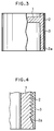
- pitches P 1 and P 2 of the spiral groove 2 and the smaller spiral groove 2a are, for example, 0.277 mm and 0.115 mm respectively, and an angle " ⁇ " of the smaller spiral groove to the axis is set to about 30°.
- hard Fe material is thermally sprayed onto the outer circumferential surface of the tappet body 1 to form a coating layer 3 having a desired thickness such as 0.3 mm, as shown in enlarged Figs. 3 and 4.
- finishing is applied to the outer circumferential surface of the coating layer 3 to make the external diameter to a fixed size and to chamfer the smaller spiral groove to the lower end of the tappet body 1 to form a chamfered portion 4.
- the angle of the chamfered portion 4 is set to 10 to 15°.
- the chamfered portion 4 is formed by cutting a corner from the middle of the smaller spiral portion 2a at the lower end of the tappet body 1.
- the chamfered portion 4 of the tappet body 1 contains the smaller spiral groove 2a which gradually increases in diameter. A crest of the smaller spiral groove 2a is not exposed on the coating layer 3 even when chamfered. Further, the area of the outer circumferential surface increases, so that adhesion strength of spraying material increases, thereby increasing peel resistance of the coating layer significantly.
- the tappet body 1 is exposed, but the exposed portion is not engaged with a bore of the cylinder head. So it is not necessary to consider wear resistance.
- a coating layer 3 similar to that in the first embodiment is formed by thermal spraying, and at the same time with finishing of the outer circumferential surface, a chamfered portion 4 is formed on the outer circumferential surface of the area where the smaller spiral groove 2a is formed.
- the angle of the smaller spiral groove 2a to the axis is equal to or larger than the angle of the chamfered portion 4, such as 10 to 60°.
- spraying material of the smaller spiral groove 2a increases in adhesion strength, thereby increasing peel resistance of the coating layer 3.
- the coating layer 3 of the smaller spiral groove 2a can be increased in thickness which is equal to the amount to be tapered. Thus, even if the coating layer 3 is cut during chamfering, a crest of the smaller spiral groove 2a is not exposed, thereby preventing the coating layer 3 from peeling off.
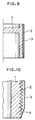
- the present invention is not limited to the foregoing embodiments in which the smaller spiral groove 2a is formed at the lower end of the tappet body 2a. But a smaller sprial groove 2c may be also formed at the upper end of the tappet body 1 as shown in Figs. 7 and 8. Thus, similar to the above, the chamfered portion 4 is formed at the upper end of the tappet body 1 after the coating layer 6 is formed, thereby increasing peel resistance of the coating layer 3.
- the present invention may be applied to Ti alloy tappet.
- the coating layer 3 may be formed by plating instead of thermal spraying.
Landscapes
- Engineering & Computer Science (AREA)
- Mechanical Engineering (AREA)
- General Engineering & Computer Science (AREA)
- Valve-Gear Or Valve Arrangements (AREA)
Applications Claiming Priority (3)
| Application Number | Priority Date | Filing Date | Title |
|---|---|---|---|
| JP234818/96 | 1996-09-05 | ||
| JP23481896 | 1996-09-05 | ||
| JP8234818A JPH1077807A (ja) | 1996-09-05 | 1996-09-05 | 内燃機関用タペットの製造方法 |
Publications (3)
| Publication Number | Publication Date |
|---|---|
| EP0828060A2 true EP0828060A2 (fr) | 1998-03-11 |
| EP0828060A3 EP0828060A3 (fr) | 1998-06-10 |
| EP0828060B1 EP0828060B1 (fr) | 1999-12-01 |
Family
ID=16976874
Family Applications (1)
| Application Number | Title | Priority Date | Filing Date |
|---|---|---|---|
| EP97115097A Expired - Lifetime EP0828060B1 (fr) | 1996-09-05 | 1997-09-01 | Procédé de fabrication d'un poussoir de moteur à combustion interne |
Country Status (4)
| Country | Link |
|---|---|
| US (1) | US5918366A (fr) |
| EP (1) | EP0828060B1 (fr) |
| JP (1) | JPH1077807A (fr) |
| DE (1) | DE69700868T2 (fr) |
Families Citing this family (4)
| Publication number | Priority date | Publication date | Assignee | Title |
|---|---|---|---|---|
| JP4103876B2 (ja) | 2004-09-17 | 2008-06-18 | 日産自動車株式会社 | 溶射前処理方法およびエンジンのシリンダブロックならびに溶射前処理装置 |
| JP4107282B2 (ja) | 2004-10-15 | 2008-06-25 | 日産自動車株式会社 | 溶射前処理方法およびエンジンのシリンダブロックならびに溶射前処理装置 |
| JP4645468B2 (ja) * | 2006-02-10 | 2011-03-09 | 日産自動車株式会社 | シリンダボア内面の加工方法およびシリンダブロック |
| US10809448B1 (en) * | 2019-04-18 | 2020-10-20 | Facebook Technologies, Llc | Reducing demolding stress at edges of gratings in nanoimprint lithography |
Family Cites Families (11)
| Publication number | Priority date | Publication date | Assignee | Title |
|---|---|---|---|---|
| US2467079A (en) * | 1944-03-06 | 1949-04-12 | Standard Screw | Method of making tappets |
| US3058454A (en) * | 1961-10-06 | 1962-10-16 | Francis J Goncalves | Hydraulic valve lifter |
| US3279446A (en) * | 1964-06-12 | 1966-10-18 | Eaton Yale & Towne | Valve tappet |
| US3715790A (en) * | 1971-01-13 | 1973-02-13 | Trw Inc | Method of reinforcing piston ring grooves |
| US4909198A (en) * | 1988-03-01 | 1990-03-20 | Toyota Jidosha Kabushiki Kaisha | Aluminum alloy valve lifter with sprayed coating and method of producing same |
| DE4117425C1 (fr) * | 1991-05-28 | 1992-07-30 | Fa. Carl Freudenberg, 6940 Weinheim, De | |
| US5280771A (en) * | 1992-09-23 | 1994-01-25 | Eaton Corporation | Direct acting hydraulic tappet |
| US5743224A (en) * | 1993-09-14 | 1998-04-28 | Unisia Jecs Corporation | Valve lifter surface and processing method thereof |
| JP3227634B2 (ja) * | 1994-11-16 | 2001-11-12 | フジオーゼックス株式会社 | 内燃機関用タペットおよびその製造方法 |
| JPH08303216A (ja) * | 1995-05-08 | 1996-11-19 | Fuji Oozx Inc | 内燃機関用タペットの製造方法 |
| US5729900A (en) * | 1996-05-06 | 1998-03-24 | Fuji Oozx, Inc. | Method of manufacturing a tappet in an internal combustion engine |
-
1996
- 1996-09-05 JP JP8234818A patent/JPH1077807A/ja not_active Abandoned
-
1997
- 1997-08-28 US US08/919,488 patent/US5918366A/en not_active Expired - Fee Related
- 1997-09-01 EP EP97115097A patent/EP0828060B1/fr not_active Expired - Lifetime
- 1997-09-01 DE DE69700868T patent/DE69700868T2/de not_active Expired - Fee Related
Non-Patent Citations (1)
| Title |
|---|
| None |
Also Published As
| Publication number | Publication date |
|---|---|
| JPH1077807A (ja) | 1998-03-24 |
| DE69700868D1 (de) | 2000-01-05 |
| EP0828060A3 (fr) | 1998-06-10 |
| US5918366A (en) | 1999-07-06 |
| EP0828060B1 (fr) | 1999-12-01 |
| DE69700868T2 (de) | 2000-06-29 |
Similar Documents
| Publication | Publication Date | Title |
|---|---|---|
| KR100306922B1 (ko) | 실린더라이너및그제조방법 | |
| EP0618040B1 (fr) | Procédé de traitement de surface d'un poussoir de soupape | |
| JPH10252891A (ja) | アルミシリンダ用第二圧力リングおよびその製造方法 | |
| US5918366A (en) | Method of forming a tappet in an internal combustion engine | |
| WO2004033757A3 (fr) | Outil avec revetement a faible coefficient de frottement resistant a l'usure et procede de fabrication de celui-ci | |
| JP3227634B2 (ja) | 内燃機関用タペットおよびその製造方法 | |
| US5970613A (en) | Method of manufacturing a wear resistant cylinder | |
| US6209197B1 (en) | Method of manufacturing tappet in an internal combustion engine | |
| US5000127A (en) | Cylinder sleeve for two-cycle engine | |
| US5729900A (en) | Method of manufacturing a tappet in an internal combustion engine | |
| EP0806549B1 (fr) | Poussoir de moteur à combustion interne et méthode de fabrication | |
| WO2011111615A1 (fr) | Procédé d'usinage de bloc-cylindres, bloc-cylindres, et bloc-cylindres pour pulvérisation thermique | |
| JPH09262714A (ja) | ボールエンドミル | |
| JPH0417303Y2 (fr) | ||
| KR20020028605A (ko) | 억지 끼워 맞춤용 고마찰 코팅방법 | |
| JP3430427B2 (ja) | バルブリフタの表面処理方法 | |
| JPS5969207A (ja) | 深穴明け加工用工具の製造方法 | |
| JPH07243307A (ja) | バルブリフタの表面処理方法 | |
| JP2581026Y2 (ja) | 内燃機関用ピストン | |
| JPH094422A (ja) | 耐摩耗性の円筒体及びその製造方法 | |
| JP2508706B2 (ja) | ろう付けドリル | |
| GB2245327A (en) | Tappets | |
| CN121798016A (zh) | 一种芯部设有不完全覆盖涂层的钻削刀具 | |
| JPH08199326A (ja) | 溶射用ワーク保持具 | |
| JPH0275434A (ja) | トリミングダイス |
Legal Events
| Date | Code | Title | Description |
|---|---|---|---|
| PUAI | Public reference made under article 153(3) epc to a published international application that has entered the european phase |
Free format text: ORIGINAL CODE: 0009012 |
|
| AK | Designated contracting states |
Kind code of ref document: A2 Designated state(s): DE FR GB IT |
|
| AX | Request for extension of the european patent |
Free format text: AL;LT;LV;RO;SI |
|
| PUAL | Search report despatched |
Free format text: ORIGINAL CODE: 0009013 |
|
| AK | Designated contracting states |
Kind code of ref document: A3 Designated state(s): AT BE CH DE DK ES FI FR GB GR IE IT LI LU MC NL PT SE |
|
| AX | Request for extension of the european patent |
Free format text: AL;LT;LV;RO;SI |
|
| 17P | Request for examination filed |
Effective date: 19980604 |
|
| 17Q | First examination report despatched |
Effective date: 19980720 |
|
| GRAG | Despatch of communication of intention to grant |
Free format text: ORIGINAL CODE: EPIDOS AGRA |
|
| AKX | Designation fees paid |
Free format text: DE FR GB IT |
|
| RBV | Designated contracting states (corrected) |
Designated state(s): DE FR GB IT |
|
| GRAG | Despatch of communication of intention to grant |
Free format text: ORIGINAL CODE: EPIDOS AGRA |
|
| GRAH | Despatch of communication of intention to grant a patent |
Free format text: ORIGINAL CODE: EPIDOS IGRA |
|
| GRAH | Despatch of communication of intention to grant a patent |
Free format text: ORIGINAL CODE: EPIDOS IGRA |
|
| GRAA | (expected) grant |
Free format text: ORIGINAL CODE: 0009210 |
|
| AK | Designated contracting states |
Kind code of ref document: B1 Designated state(s): DE FR GB IT |
|
| PG25 | Lapsed in a contracting state [announced via postgrant information from national office to epo] |
Ref country code: IT Free format text: LAPSE BECAUSE OF FAILURE TO SUBMIT A TRANSLATION OF THE DESCRIPTION OR TO PAY THE FEE WITHIN THE PRE;WARNING: LAPSES OF ITALIAN PATENTS WITH EFFECTIVE DATE BEFORE 2007 MAY HAVE OCCURRED AT ANY TIME BEFORE 2007. THE CORRECT EFFECTIVE DATE MAY BE DIFFERENT FROM THE ONE RECORDED.SCRIBED TIME-LIMIT Effective date: 19991201 Ref country code: FR Free format text: LAPSE BECAUSE OF FAILURE TO SUBMIT A TRANSLATION OF THE DESCRIPTION OR TO PAY THE FEE WITHIN THE PRESCRIBED TIME-LIMIT Effective date: 19991201 |
|
| REF | Corresponds to: |
Ref document number: 69700868 Country of ref document: DE Date of ref document: 20000105 |
|
| EN | Fr: translation not filed | ||
| PLBE | No opposition filed within time limit |
Free format text: ORIGINAL CODE: 0009261 |
|
| STAA | Information on the status of an ep patent application or granted ep patent |
Free format text: STATUS: NO OPPOSITION FILED WITHIN TIME LIMIT |
|
| 26N | No opposition filed | ||
| REG | Reference to a national code |
Ref country code: GB Ref legal event code: IF02 |
|
| PGFP | Annual fee paid to national office [announced via postgrant information from national office to epo] |
Ref country code: DE Payment date: 20030830 Year of fee payment: 7 |
|
| PGFP | Annual fee paid to national office [announced via postgrant information from national office to epo] |
Ref country code: GB Payment date: 20030901 Year of fee payment: 7 |
|
| PG25 | Lapsed in a contracting state [announced via postgrant information from national office to epo] |
Ref country code: GB Free format text: LAPSE BECAUSE OF NON-PAYMENT OF DUE FEES Effective date: 20040901 |
|
| PG25 | Lapsed in a contracting state [announced via postgrant information from national office to epo] |
Ref country code: DE Free format text: LAPSE BECAUSE OF NON-PAYMENT OF DUE FEES Effective date: 20050401 |
|
| GBPC | Gb: european patent ceased through non-payment of renewal fee |
Effective date: 20040901 |