EP0829621A2 - Un mécanisme de variation du calage des soupapes - Google Patents
Un mécanisme de variation du calage des soupapes Download PDFInfo
- Publication number
- EP0829621A2 EP0829621A2 EP97115698A EP97115698A EP0829621A2 EP 0829621 A2 EP0829621 A2 EP 0829621A2 EP 97115698 A EP97115698 A EP 97115698A EP 97115698 A EP97115698 A EP 97115698A EP 0829621 A2 EP0829621 A2 EP 0829621A2
- Authority
- EP
- European Patent Office
- Prior art keywords
- oil
- pressure chamber
- filter
- camshaft
- engine
- Prior art date
- Legal status (The legal status is an assumption and is not a legal conclusion. Google has not performed a legal analysis and makes no representation as to the accuracy of the status listed.)
- Granted
Links
Images



Classifications
-
- F—MECHANICAL ENGINEERING; LIGHTING; HEATING; WEAPONS; BLASTING
- F01—MACHINES OR ENGINES IN GENERAL; ENGINE PLANTS IN GENERAL; STEAM ENGINES
- F01L—CYCLICALLY OPERATING VALVES FOR MACHINES OR ENGINES
- F01L1/00—Valve-gear or valve arrangements, e.g. lift-valve gear
- F01L1/34—Valve-gear or valve arrangements, e.g. lift-valve gear characterised by the provision of means for changing the timing of the valves without changing the duration of opening and without affecting the magnitude of the valve lift
- F01L1/344—Valve-gear or valve arrangements, e.g. lift-valve gear characterised by the provision of means for changing the timing of the valves without changing the duration of opening and without affecting the magnitude of the valve lift changing the angular relationship between crankshaft and camshaft, e.g. using helicoidal gear
- F01L1/3442—Valve-gear or valve arrangements, e.g. lift-valve gear characterised by the provision of means for changing the timing of the valves without changing the duration of opening and without affecting the magnitude of the valve lift changing the angular relationship between crankshaft and camshaft, e.g. using helicoidal gear using hydraulic chambers with variable volume to transmit the rotating force
-
- F—MECHANICAL ENGINEERING; LIGHTING; HEATING; WEAPONS; BLASTING
- F01—MACHINES OR ENGINES IN GENERAL; ENGINE PLANTS IN GENERAL; STEAM ENGINES
- F01L—CYCLICALLY OPERATING VALVES FOR MACHINES OR ENGINES
- F01L1/00—Valve-gear or valve arrangements, e.g. lift-valve gear
- F01L1/34—Valve-gear or valve arrangements, e.g. lift-valve gear characterised by the provision of means for changing the timing of the valves without changing the duration of opening and without affecting the magnitude of the valve lift
- F01L1/344—Valve-gear or valve arrangements, e.g. lift-valve gear characterised by the provision of means for changing the timing of the valves without changing the duration of opening and without affecting the magnitude of the valve lift changing the angular relationship between crankshaft and camshaft, e.g. using helicoidal gear
- F01L1/3442—Valve-gear or valve arrangements, e.g. lift-valve gear characterised by the provision of means for changing the timing of the valves without changing the duration of opening and without affecting the magnitude of the valve lift changing the angular relationship between crankshaft and camshaft, e.g. using helicoidal gear using hydraulic chambers with variable volume to transmit the rotating force
- F01L2001/34423—Details relating to the hydraulic feeding circuit
- F01L2001/34426—Oil control valves
-
- F—MECHANICAL ENGINEERING; LIGHTING; HEATING; WEAPONS; BLASTING
- F01—MACHINES OR ENGINES IN GENERAL; ENGINE PLANTS IN GENERAL; STEAM ENGINES
- F01L—CYCLICALLY OPERATING VALVES FOR MACHINES OR ENGINES
- F01L1/00—Valve-gear or valve arrangements, e.g. lift-valve gear
- F01L1/34—Valve-gear or valve arrangements, e.g. lift-valve gear characterised by the provision of means for changing the timing of the valves without changing the duration of opening and without affecting the magnitude of the valve lift
- F01L1/344—Valve-gear or valve arrangements, e.g. lift-valve gear characterised by the provision of means for changing the timing of the valves without changing the duration of opening and without affecting the magnitude of the valve lift changing the angular relationship between crankshaft and camshaft, e.g. using helicoidal gear
- F01L1/3442—Valve-gear or valve arrangements, e.g. lift-valve gear characterised by the provision of means for changing the timing of the valves without changing the duration of opening and without affecting the magnitude of the valve lift changing the angular relationship between crankshaft and camshaft, e.g. using helicoidal gear using hydraulic chambers with variable volume to transmit the rotating force
- F01L2001/34423—Details relating to the hydraulic feeding circuit
- F01L2001/34426—Oil control valves
- F01L2001/34433—Location oil control valves
-
- F—MECHANICAL ENGINEERING; LIGHTING; HEATING; WEAPONS; BLASTING
- F01—MACHINES OR ENGINES IN GENERAL; ENGINE PLANTS IN GENERAL; STEAM ENGINES
- F01L—CYCLICALLY OPERATING VALVES FOR MACHINES OR ENGINES
- F01L1/00—Valve-gear or valve arrangements, e.g. lift-valve gear
- F01L1/34—Valve-gear or valve arrangements, e.g. lift-valve gear characterised by the provision of means for changing the timing of the valves without changing the duration of opening and without affecting the magnitude of the valve lift
- F01L1/344—Valve-gear or valve arrangements, e.g. lift-valve gear characterised by the provision of means for changing the timing of the valves without changing the duration of opening and without affecting the magnitude of the valve lift changing the angular relationship between crankshaft and camshaft, e.g. using helicoidal gear
- F01L1/3442—Valve-gear or valve arrangements, e.g. lift-valve gear characterised by the provision of means for changing the timing of the valves without changing the duration of opening and without affecting the magnitude of the valve lift changing the angular relationship between crankshaft and camshaft, e.g. using helicoidal gear using hydraulic chambers with variable volume to transmit the rotating force
- F01L2001/34423—Details relating to the hydraulic feeding circuit
- F01L2001/34436—Features or method for avoiding malfunction due to foreign matters in oil
- F01L2001/3444—Oil filters
Definitions
- the present invention relates to a variable valve timing mechanism provided in an engine to change the valve timing of intake valves or exhaust valves. More particularly, the present invention pertains to a variable valve timing mechanism that is driven by fluid pressure.
- VVT variable valve timing mechanism
- An engine to displace the rotational phase of a camshaft and adjust the valve timing of either an intake valve or an exhaust valve.
- the operation of the VVT optimizes the valve timing in accordance with the operating state of the engine (engine load, engine speed, and other factors). This improves fuel economy, increases engine power, and suppresses undesirable engine emissions regardless of different operating states of the engine.
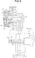
- Japanese Unexamined Patent Publication No. 8-28219 discloses a vane type VVT, an example of which is shown in Fig. 6.
- a VVT 81 includes a camshaft 82, a ring gear 84 and a cover 96.
- the ring gear 84 has helical splines 83 formed on the periphery.
- the cover 96 is fitted on the camshaft 82 with the ring gear 84 placed in between.
- the ring gear 84 is urged leftward (as viewed in the drawing) by a spring 85.
- a pulley 92 is secured to the cover 96 and coupled to the crankshaft of an engine (both not shown).
- the VVT 81 also includes hydraulic chambers 88, 89 defined next to the front and rear end faces of the ring gear 84, respectively.
- the oil pressure from an oil pump 86 is controlled by a linear solenoid type oil control valve (OCV) 87.
- OCV oil control valve
- the controlled pressure is selectively communicated with the hydraulic chambers 88 and 89 defined in the VVT 81.
- the OCV 87 includes a sleeve 90 and a spool 91.
- the spool 91 is slidably accommodated in the sleeve 90.
- a linear solenoid 95 is secured to one end of the sleeve 90 for reciprocating the spool 91.
- the position of the spool 91 in the sleeve 90 is changed by controlling the current. Accordingly, the pressure of oil discharged from the OCV 87 is controlled and the oil is selectively supplied to the hydraulic chambers 88 and 89.
- the filter 94 generally includes a fine mesh for improving its performance, that is, for catching smaller foreign matter.
- flow resistance of the oil passing through the filter 94 becomes great and significantly lowers the pressure of the oil downstream of the filter 94. This deteriorates the response of the VVT 81, which is driven by the pressure of the oil.
- the filter 94 is provided on a cover covering the camshaft 82. This construction exposes the housing of the filter 94 to the ambient air, which cools the oil and thus further increases its flow resistance. This further reduces the responsiveness of the VVT.
- the present invention provides an apparatus for adjusting the valve performance of an internal combustion engine valve.
- the apparatus has a pressure chamber for receiving oil, wherein the apparatus is hydraulically driven by the oil pressure.
- the apparatus includes a reservoir for reserving oil, a pump for discharging the oil from the reservoir, a control valve for controlling the oil flow from the pump, a passage for connecting the control valve to the pressure chamber to supply the oil to the pressure chamber, a filter positioned in the passage for filtering the oil, and a heater for heating the filter to a temperature that is approximately the same as that of an interior part of the engine.
- variable valve timing mechanism according to the present invention will be described below referring to Figs. 1 to 5.
- FIG. 3 An engine 12 having a valve train that includes a vane-type VVT 11 is shown in Fig. 3.
- the engine 12 includes an oil pan 13 for reserving lubricating oil, a cylinder block 14 provided with cylinders (not shown) and a cylinder head 19.
- the cylinder head 19 supports an exhaust camshaft 15, an intake camshaft 16, exhaust valves 17 and intake valves 18.
- the cylinder block 14 rotatably supports a crankshaft 20.
- Tensioners 21, 22 are arranged at predetermined positions on the cylinder block 14.
- the cylinder head 19 rotatably supports the exhaust camshaft 15 for opening and closing the exhaust valves 17.
- the cylinder head 19 also rotatably supports the intake camshaft 16 for opening and closing the intake valves 18.
- a drive gear 23, which is attached to the exhaust camshaft 15 is meshed with a driven gear 24 attached to the intake camshaft 16.
- the VVT 11 is provided at a distal end of the intake camshaft 16.
- Sprockets 25, 26 are provided at distal ends of the crankshaft 20 and the exhaust camshaft 15, respectively.
- a chain 27 is wound about the sprockets 25, 26 to connect the exhaust camshaft 15 to the crankshaft 20. Tension is applied to the wound chain 27 by the tensioners 21, 22.
- the rotation of the crankshaft 20 is transmitted to the camshaft 15 by means of the chain 27 and the sprockets 25, 26. Then, the rotation of the exhaust camshaft 15 is transmitted to the intake camshaft 16 by means of the gears 23, 24. This rotates the camshafts 15, 16 synchronously with the crankshaft 20. The rotation of the camshafts 15, 16 selectively opens and closes the associated exhaust and intake valves 17, 18 in accordance with a predetermined timing.
- Fig. 1 is a cross-sectional view illustrating a VVT 11 provided on the distal end of the intake camshaft (hereinafter referred to as "camshaft") 16, an oil pump 31 for supplying oil to the VVT 11 and an oil control valve (OCV) 32 for controlling the pressure of oil supplied to the VVT 11.
- VVT 11 provided on the distal end of the intake camshaft (hereinafter referred to as "camshaft") 16
- OCV oil control valve
- the VVT 11 contains the camshaft 16, a rotor 35 fixed to the left end of the camshaft 16, a housing 39 surrounding the rotor 35, the driven gear 24 fixed to the housing 39 and a cover 40 covering the housing 39.
- the camshaft 16 is rotatably supported by the cylinder head 19 and a bearing cap 33.
- the rotor 35 is fixed to the left end of the camshaft 16 by a bolt 34 and is rotated integrally with the camshaft 16.
- the rotor 35 has a plurality of vanes 37.
- the housing 39 surrounds the rotor 35 and is rotatable relative to the camshaft 16 and the rotor 35.
- the cover 40 and the driven gear 24 are fixed to opposite sides of the housing 39, respectively, by bolts 41 and are both rotatable relative to the camshaft 16 and the rotor 35.
- the driven gear 24 has a thick ring-like shape and has a plurality of outer teeth 38 formed on its circumference.
- the driven gear 24 is rotatably supported on outer surface of the camshaft 16.
- One of the vanes 37 has a hole 44 extending parallel to the axis of the camshaft 16.
- a lock pin 45 is slidably accommodated in the hole 44.
- the lock pin 45 has a recess 46 defined therein.
- a spring 47 is housed in the recess 46 for urging the pin 45 toward the cover 40.
- the cover 40 has a recess 48 with which the pin 45 is engaged in the view of Fig. 1. Engagement of the pin 45 with the recess 48 restricts rotation of the rotor 35 relative to the housing 39. Accordingly, the camshaft 16 rotates integrally with the driven gear 24 when the pin 45 engages the recess 48.
- the housing 39 and the rotor 35 are rotated clockwise.
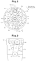
- the housing 39 and the rotor 35 shown in Fig. 2 are in their initial positions, at which the valve timing of the intake valves 18 is delayed most.
- the rotor 35 consists of a boss 49 and the above mentioned vanes 37, the number of which is four in this embodiment.
- the vanes 37 protrude radially outward from the boss 49. These four vanes 37 are arranged at approximately 90 degree intervals.
- a seal 51 is attached to the distal end of each vane 37 to seal between the inner circumference of the housing 39 and the outer circumference of the boss 49.
- the housing 39 has four inward protrusions 43, and every two adjacent protrusions 43 define a recess.
- the outer circumference of the boss 49 is brought into contact with the end faces of the protrusions 43.
- the vanes 37 are housed in the recesses of the housing 39 respectively.
- Each vane 37 defines, in the corresponding recess, a first hydraulic chamber 53 and a second hydraulic chamber 54.
- the first hydraulic chamber 53 is located on the trailing side with respect to the rotating direction of the vane 37, while the second hydraulic chamber 54 is located on the leading side. Oil pressure is supplied to the hydraulic chambers 53, 54 selectively so as to rotate the rotor 35 with respect to the housing 39.
- the hole 44 which is defined in one of the vanes 37 for accommodating the lock pin 45, is communicated with one of the first hydraulic chambers 53 by an oil passage 29. As described below, oil is supplied to the hole 44 through the passage 29, and the pressure of the supplied oil moves the lock pin 45 rightward against the force of the spring 47 (shown in Fig. 1). This permits the rotor 35 to rotate relative to the housing 39.
- the housing 39 is fixed to the driven gear 24 and the cover 40 (shown in Fig. 1) by the bolts 41 and a knock-pin 28 provided in one of the protrusions 43.
- the cylinder head 19 has first and second oil conduits 55, 56 defined therein.
- the conduits 55, 56 are aligned and therefore only one is visible.
- the OCV 32 is covered with a housing 36 and has a plurality of ports 69-73 (shown in Fig. 4).
- the port 73 is connected to the oil pan 13 by a supply passage 57, an oil filter 58, a pump 31 and an oil strainer 59.
- the first oil conduit 55 is communicated with an oil groove 65 formed in the top portion of the cylinder head 19 and the bearing cap 33.
- An oil hole 66 and an oil passage 67 are formed in the camshaft 16 for communicating the groove 65 with oil bores 68.
- the oil bores 68 communicate the first hydraulic chambers 53 and the oil passage 67 thereby supplying oil to the chambers 53.
- An annular release chamber 79 is defined about the lock pin 45.
- the chamber 79 is communicated with the oil passage 29 (Fig. 2).
- the passage 29 (shown in Fig. 2) communicates the supplied oil pressure with the release chamber 79.
- the oil pressure moves the lock pin 45 rightward as viewed in Fig. 1 against the force of the spring 47 thereby disengaging the pin 45 from the recess 48.
- This allows the rotor 35 to rotate with respect to the housing 39. Therefore, the oil pressure supplied to the first hydraulic chambers 53 rotates the rotor 35 clockwise relative to the housing 39 (as viewed in Fig. 2).
- the rotational phase of the camshaft 16 is advanced.
- the valve timing of the intake valves 18 (shown in Fig. 3), which are driven by the shaft 16, is advanced.
- An oil passage 62 is formed in the camshaft 16 substantially along the axis of the shaft 16, and an oil groove 60 is formed in the inner surface of the cylinder head 19 and the bearing cap 33.
- the second oil conduit 56 is communicated with the oil passage 62 by the oil groove 60 and an oil hole 61.
- One end of the passage 62 opens to an annular chamber 63 defined in the boss 49 of the rotor 35.
- four oil passages 64 are radially formed in the boss 49 of the rotor 35 for communicating the annular chamber 63 with the second hydraulic chambers 54.
- the passages 64 supply oil from the chamber 63 to the second hydraulic chambers 54.
- the OCV 32 has five ports 69-73 to switch the direction of supplying and discharging the oil and to adjust the oil pressure supplied to the hydraulic chambers 53 and 54, respectively.
- a first port 69 is connected to the first oil conduit 55, while a second port 70 is connected to the second oil conduit 56.
- Drain ports 71, 72 are connected to the oil pan 13 (shown in Fig. 1), while a supply port 73 is connected via a supply passage 57 and the oil filter 58 to the pump 31 (shown in Fig. 1).
- the OCV 32 is provided with a solenoid actuator 75, a spool 74 and a coil spring 76 for moving the spool 74.
- An electronic control unit (ECU, not shown) duty controls the solenoid 75 for reciprocating the spool 74 in the axial direction. This reciprocating motion of the spool 74 adjusts of the amount of oil supplied to the hydraulic chambers 53, 54.
- the spring 76 is located in the housing 36 for urging the spool 74 rightward as viewed in Fig. 4, or toward a "retarded position". Stopping the supply of current to the solenoid 75 allows the spring 76 to move the spool 74 to the "retarded position".
- oil is supplied to the second hydraulic chambers 54 in the VVT 11 and thus the valve timing of the intake valves 18 is retarded.
- supplying current to the solenoid 75 moves the spool 74 leftward as viewed in Fig. 4, or toward an "advanced position".
- oil is supplied to the first hydraulic chambers 53 and thus the valve timing of the intake valves 18 is advanced.
- the oil filter 58 for removing foreign matter from oil is located between the pump 31 (shown in Fig. 1) and the supply passage 57.
- the filter 58 is located in a water jacket 77 (shown in Fig. 5) of the engine 12.
- Fig. 5 is a cross-sectional view of the engine 12 as viewed from the rear side and accurately shows the position of the filter 58 in the engine 12.
- the water jacket 77 is defined in the cylinder head 19. Coolant water circulates in the jacket 77 for cooling the engine 12.
- the oil filter 58 is held in an inclined position by a holder 78 formed in the jacket 77.
- the holder 78 is exposed to the coolant water. Specifically, the lower portion of the holder 78 extends into the water jacket 77 for enlarging the area contacting the coolant water.
- the oil filter 58 includes a fine mesh for catching minute foreign matter in the oil.
- the VVT 11 is actuated by oil pressure supplied to the first and second hydraulic chambers 53, 54, and changes the valve timing of the intake valves 18.
- the pump 31 supplies oil to the OCV 32 via the oil filter 58.
- the OCV 32 controls the pressure of the oil discharged therefrom. Minute foreign matter is caught by the filter 58 and removed from the oil.
- the temperature of the oil is low, for example, when the engine 12 is first started. At this time, the temperature of the oil filter 58 is also low.
- the temperature of the oil filter 58 affects the flow resistance of the oil passing through the filter 58.
- the low temperature of the oil filter 58 raises the flow resistance of the oil in the vicinity of the oil filter 58, which affects all of the oil in circulation.
- the oil filter 58 is exposed to the coolant water circulating in the water jacket 77. Thus, as the coolant water is warmed, the heat of the coolant water raises the temperature of the oil filter 58.
- the water jacket 77 and the coolant water therefore serve as a heater for the oil filter 58.
- Heat of the coolant water quickly raises the temperature of the oil filter 58. Accordingly, the flow resistance of the oil in the vicinity of the filter 58 is lowered and thus improved.
- the above described apparatus improves the flow resistance of oil in the vicinity of the oil filter 58.
- quick VVT response is achieved soon after the engine 12 is started.
- the temperature of the oil may be higher than the temperature of the coolant water. In this case, the oil is cooled by the coolant water. This prevents the oil temperature from becoming too high. If the oil temperature is too high, the clearances between each sliding part in the VVT 11 is enlarged and the oil may leak from the clearances. This results in lower hydraulic pressure in the VVT 11, thereby deteriorating the response of the VVT 11.
- the illustrated apparatus prevents the oil temperature from being too high thereby improving the response of the VVT 11 when the engine 12 is running under heavy load.
- the coolant water cools the engine 12 and, at the same time, warms the oil filter 58. In this manner, the heat of the engine 12 is effectively used. This eliminates the necessity for an extra device for heating the oil filter 58.
Landscapes
- Engineering & Computer Science (AREA)
- Mechanical Engineering (AREA)
- General Engineering & Computer Science (AREA)
- Valve Device For Special Equipments (AREA)
- Valve-Gear Or Valve Arrangements (AREA)
- Lubrication Details And Ventilation Of Internal Combustion Engines (AREA)
- Output Control And Ontrol Of Special Type Engine (AREA)
- Lubrication Of Internal Combustion Engines (AREA)
Applications Claiming Priority (3)
| Application Number | Priority Date | Filing Date | Title |
|---|---|---|---|
| JP24360496 | 1996-09-13 | ||
| JP243604/96 | 1996-09-13 | ||
| JP24360496A JPH1089024A (ja) | 1996-09-13 | 1996-09-13 | 内燃機関のバルブ特性可変機構 |
Publications (3)
| Publication Number | Publication Date |
|---|---|
| EP0829621A2 true EP0829621A2 (fr) | 1998-03-18 |
| EP0829621A3 EP0829621A3 (fr) | 1998-04-15 |
| EP0829621B1 EP0829621B1 (fr) | 2001-12-05 |
Family
ID=17106290
Family Applications (1)
| Application Number | Title | Priority Date | Filing Date |
|---|---|---|---|
| EP97115698A Expired - Lifetime EP0829621B1 (fr) | 1996-09-13 | 1997-09-10 | Un mécanisme de variation du calage des soupapes |
Country Status (5)
| Country | Link |
|---|---|
| US (1) | US5797363A (fr) |
| EP (1) | EP0829621B1 (fr) |
| JP (1) | JPH1089024A (fr) |
| KR (1) | KR100296758B1 (fr) |
| DE (1) | DE69708801T2 (fr) |
Cited By (19)
| Publication number | Priority date | Publication date | Assignee | Title |
|---|---|---|---|---|
| WO1999061759A1 (fr) * | 1998-05-27 | 1999-12-02 | Dr. Ing. H.C.F. Porsche Aktiengesellschaft | Dispositif de modification relative de la position en rotation d'un arbre par rapport au pignon d'entree |
| EP0945598A3 (fr) * | 1998-03-27 | 2000-06-07 | Yamaha Hatsudoki Kabushiki Kaisha | Moteur à combustion interne à 4 temps |
| EP1046793A3 (fr) * | 1999-04-21 | 2002-08-21 | Ford Global Technologies, Inc. | Dispositif de calage de soupape variable et méthode |
| EP1081340A3 (fr) * | 1999-09-03 | 2002-08-21 | Honda Giken Kogyo Kabushiki Kaisha | Conduit d'alimentation en huile pour un dispositif de commande de soupape dans un moteur à combustion interne |
| US6672283B2 (en) | 2000-06-09 | 2004-01-06 | Yamaha Marine Kabushiki Kaisha | Four-cycle engine for marine drive |
| US6708659B2 (en) | 2001-07-25 | 2004-03-23 | Yamaha Marine Kabushiki Kaisha | Four cycle engine for marine drive |
| US6748911B2 (en) | 2001-07-02 | 2004-06-15 | Yamaha Marine Kabushiki Kaisha | Valve timing control for marine engine |
| US6752108B2 (en) | 2000-05-31 | 2004-06-22 | Yamaha Marine Kabushiki Kaisha | Four-cycle engine for marine drive |
| US6755163B2 (en) | 2001-06-22 | 2004-06-29 | Yamaha Marine Kabushiki Kaisha | Control device for four cycle engine of outboard motor |
| US6800002B2 (en) | 2001-07-02 | 2004-10-05 | Yamaha Marine Kabushiki Kaisha | Valve timing control for marine engine |
| US6857405B2 (en) | 2001-07-25 | 2005-02-22 | Yamaha Marine Kabushiki Kaisha | Valve timing control for marine engine |
| US6860246B2 (en) | 2001-07-04 | 2005-03-01 | Yamaha Marine Kabushiki Kaisha | Valve timing control for marine engine |
| EP1340886A4 (fr) * | 2000-12-04 | 2005-06-22 | Mitsubishi Electric Corp | Soupape de commande d'ecoulement d'huile et son procede de montage |
| US6910450B2 (en) | 2000-05-31 | 2005-06-28 | Yamaha Marine Kabushiki Kaisha | Variable valve timing structure for outboard motor engine |
| US6938594B2 (en) | 2001-06-21 | 2005-09-06 | Yamaha Marine Kabushiki Kaisha | Valve timing control for marine engine |
| US6957635B2 (en) | 2001-06-29 | 2005-10-25 | Yamaha Marine Kabushiki Kaisha | Valve timing control for marine engine |
| DE19922194B4 (de) * | 1998-12-07 | 2006-06-29 | Mitsubishi Denki K.K. | Hydro-Stellorgan mit Radschaufeln |
| WO2006119210A3 (fr) * | 2005-05-02 | 2007-01-11 | Borgwarner Inc | Phaseur de calage comprenant un distributeur a tiroir cylindrique a decalage |
| CN102650223A (zh) * | 2012-05-25 | 2012-08-29 | 重庆大学 | 摩托车双顶置凸轮轴发动机进气相位连续可变机构 |
Families Citing this family (24)
| Publication number | Priority date | Publication date | Assignee | Title |
|---|---|---|---|---|
| SE522177C2 (sv) * | 1996-08-27 | 2004-01-20 | Mitsubishi Motors Corp | Styranordning för en förbränningsmotor med cylinderinsprutning och gnisttändning |
| GB2329675A (en) * | 1997-09-27 | 1999-03-31 | Mechadyne Ltd | I.c. engine front cover with oil supply passages |
| JP3847428B2 (ja) * | 1997-11-19 | 2006-11-22 | ヤマハ発動機株式会社 | 内燃エンジンのシリンダヘッド構造 |
| JPH11303615A (ja) * | 1998-04-24 | 1999-11-02 | Yamaha Motor Co Ltd | 可変バルブタイミング装置付きエンジン |
| JPH11343820A (ja) * | 1998-06-03 | 1999-12-14 | Unisia Jecs Corp | 内燃機関のバルブタイミング制御装置 |
| JP3536692B2 (ja) * | 1998-12-07 | 2004-06-14 | トヨタ自動車株式会社 | 内燃機関のバルブタイミング制御装置 |
| US6332441B1 (en) * | 1999-02-22 | 2001-12-25 | Honda Giken Kogyo | Assembling arrangement for tensioner and hydraulic control valve |
| JP2001050102A (ja) * | 1999-05-31 | 2001-02-23 | Yamaha Motor Co Ltd | 4サイクルエンジン |
| US6308672B1 (en) * | 1999-08-05 | 2001-10-30 | Delphi Technologies, Inc. | Front-mounting cam phaser module |
| KR100406777B1 (ko) * | 1999-08-17 | 2003-11-21 | 가부시키가이샤 덴소 | 가변밸브 타이밍 제어장치 |
| JP3912474B2 (ja) * | 2000-01-31 | 2007-05-09 | スズキ株式会社 | オイル通路構造 |
| JP3561467B2 (ja) | 2000-10-25 | 2004-09-02 | 本田技研工業株式会社 | エンジンの動弁制御装置 |
| US6484680B2 (en) * | 2001-03-10 | 2002-11-26 | Ford Global Technologies, Inc. | Internal combustion engine with variable cam timing oil filter with restrictor arrangement |
| JP4585133B2 (ja) * | 2001-03-27 | 2010-11-24 | 本田技研工業株式会社 | 車両用可変バルブタイミングエンジン |
| JP3935704B2 (ja) * | 2001-10-16 | 2007-06-27 | 三菱電機株式会社 | バルブタイミング調整装置 |
| DE10243738A1 (de) * | 2002-09-20 | 2004-03-25 | Mann + Hummel Gmbh | Flüssigkeitsfilter, insbesondere Ölfilter für Kraftfahrzeuge |
| KR20040039899A (ko) * | 2002-11-05 | 2004-05-12 | 현대자동차주식회사 | 연속가변 밸브타이밍 시스템의 오작동방지를 위한오일회로의 오일필터 |
| KR100507106B1 (ko) * | 2002-12-06 | 2005-08-09 | 현대자동차주식회사 | 연속 가변 밸브 타이밍 시스템의 오일 컨트롤 밸브용필터장치 |
| KR100507107B1 (ko) * | 2002-12-06 | 2005-08-09 | 현대자동차주식회사 | 연속 가변 밸브 타이밍 시스템의 오일 컨트롤 밸브용필터장치 |
| KR100501283B1 (ko) * | 2002-12-06 | 2005-07-18 | 현대자동차주식회사 | 연속 가변 밸브 타이밍 시스템용 오일 냉각 장치 |
| JP5061950B2 (ja) * | 2008-02-26 | 2012-10-31 | 日産自動車株式会社 | オイルフィルタ |
| JP5940002B2 (ja) * | 2013-02-14 | 2016-06-29 | 日立オートモティブシステムズ株式会社 | 内燃機関のバルブタイミング制御システム |
| JP5967137B2 (ja) * | 2013-07-31 | 2016-08-10 | 株式会社デンソー | バルブタイミング調整装置 |
| GB2539937B (en) | 2015-07-01 | 2019-07-24 | Ford Global Tech Llc | A combined oil filter and restrictor assembly |
Family Cites Families (7)
| Publication number | Priority date | Publication date | Assignee | Title |
|---|---|---|---|---|
| US4174699A (en) * | 1977-12-27 | 1979-11-20 | General Motors Corporation | Engine oil processing system |
| JPS5554619A (en) * | 1978-10-16 | 1980-04-22 | Toyota Motor Corp | Oil filter capable of warming lubricating oil promptly |
| DE2932448A1 (de) * | 1979-08-10 | 1981-02-26 | Kloeckner Humboldt Deutz Ag | Einrichtung zum beheizen der bedienungskabine einer von einer brennkraftmaschine angetriebenen maschine |
| US4831980A (en) * | 1987-07-13 | 1989-05-23 | Toyo Radiator Co., Ltd. | Oil cooler assembly with integrated oil filter for internal combustion engine |
| US5271360A (en) * | 1990-11-08 | 1993-12-21 | Aisin Seiki Kabushiki Kaisha | Valve opening and closing timing control apparatus |
| JP3098676B2 (ja) * | 1994-07-13 | 2000-10-16 | トヨタ自動車株式会社 | 内燃機関のバルブタイミング制御装置 |
| DE19604865B4 (de) * | 1996-02-10 | 2009-05-07 | Schaeffler Kg | Mittels separater Ölfördereinrichtung beaufschlagbarer Stellzylinder eines Nockenwellenverstellers |
-
1996
- 1996-09-13 JP JP24360496A patent/JPH1089024A/ja active Pending
-
1997
- 1997-09-10 EP EP97115698A patent/EP0829621B1/fr not_active Expired - Lifetime
- 1997-09-10 DE DE69708801T patent/DE69708801T2/de not_active Expired - Fee Related
- 1997-09-11 US US08/927,997 patent/US5797363A/en not_active Expired - Fee Related
- 1997-09-12 KR KR1019970046948A patent/KR100296758B1/ko not_active Expired - Fee Related
Cited By (22)
| Publication number | Priority date | Publication date | Assignee | Title |
|---|---|---|---|---|
| EP0945598A3 (fr) * | 1998-03-27 | 2000-06-07 | Yamaha Hatsudoki Kabushiki Kaisha | Moteur à combustion interne à 4 temps |
| WO1999061759A1 (fr) * | 1998-05-27 | 1999-12-02 | Dr. Ing. H.C.F. Porsche Aktiengesellschaft | Dispositif de modification relative de la position en rotation d'un arbre par rapport au pignon d'entree |
| US6209497B1 (en) | 1998-05-27 | 2001-04-03 | Dr. Ing. H,C.F. Porsche Aktiengesellschaft | Device for changing the relative rotational position of a shaft to the drive wheel |
| CN1100197C (zh) * | 1998-05-27 | 2003-01-29 | F·波尔希名誉工学博士公司 | 相对于传动轮改变轴的相对旋转位置的装置 |
| DE19922194B4 (de) * | 1998-12-07 | 2006-06-29 | Mitsubishi Denki K.K. | Hydro-Stellorgan mit Radschaufeln |
| EP1046793A3 (fr) * | 1999-04-21 | 2002-08-21 | Ford Global Technologies, Inc. | Dispositif de calage de soupape variable et méthode |
| EP1081340A3 (fr) * | 1999-09-03 | 2002-08-21 | Honda Giken Kogyo Kabushiki Kaisha | Conduit d'alimentation en huile pour un dispositif de commande de soupape dans un moteur à combustion interne |
| US6910450B2 (en) | 2000-05-31 | 2005-06-28 | Yamaha Marine Kabushiki Kaisha | Variable valve timing structure for outboard motor engine |
| US6752108B2 (en) | 2000-05-31 | 2004-06-22 | Yamaha Marine Kabushiki Kaisha | Four-cycle engine for marine drive |
| US6672283B2 (en) | 2000-06-09 | 2004-01-06 | Yamaha Marine Kabushiki Kaisha | Four-cycle engine for marine drive |
| EP1340886A4 (fr) * | 2000-12-04 | 2005-06-22 | Mitsubishi Electric Corp | Soupape de commande d'ecoulement d'huile et son procede de montage |
| US6938594B2 (en) | 2001-06-21 | 2005-09-06 | Yamaha Marine Kabushiki Kaisha | Valve timing control for marine engine |
| US6755163B2 (en) | 2001-06-22 | 2004-06-29 | Yamaha Marine Kabushiki Kaisha | Control device for four cycle engine of outboard motor |
| US6957635B2 (en) | 2001-06-29 | 2005-10-25 | Yamaha Marine Kabushiki Kaisha | Valve timing control for marine engine |
| US6748911B2 (en) | 2001-07-02 | 2004-06-15 | Yamaha Marine Kabushiki Kaisha | Valve timing control for marine engine |
| US6800002B2 (en) | 2001-07-02 | 2004-10-05 | Yamaha Marine Kabushiki Kaisha | Valve timing control for marine engine |
| US6860246B2 (en) | 2001-07-04 | 2005-03-01 | Yamaha Marine Kabushiki Kaisha | Valve timing control for marine engine |
| US6708659B2 (en) | 2001-07-25 | 2004-03-23 | Yamaha Marine Kabushiki Kaisha | Four cycle engine for marine drive |
| US6857405B2 (en) | 2001-07-25 | 2005-02-22 | Yamaha Marine Kabushiki Kaisha | Valve timing control for marine engine |
| WO2006119210A3 (fr) * | 2005-05-02 | 2007-01-11 | Borgwarner Inc | Phaseur de calage comprenant un distributeur a tiroir cylindrique a decalage |
| US7699031B2 (en) | 2005-05-02 | 2010-04-20 | Borgwarner Inc. | Timing phaser with offset spool valve |
| CN102650223A (zh) * | 2012-05-25 | 2012-08-29 | 重庆大学 | 摩托车双顶置凸轮轴发动机进气相位连续可变机构 |
Also Published As
| Publication number | Publication date |
|---|---|
| US5797363A (en) | 1998-08-25 |
| DE69708801D1 (de) | 2002-01-17 |
| KR19980024571A (ko) | 1998-07-06 |
| EP0829621A3 (fr) | 1998-04-15 |
| KR100296758B1 (ko) | 2001-09-28 |
| DE69708801T2 (de) | 2002-06-20 |
| EP0829621B1 (fr) | 2001-12-05 |
| JPH1089024A (ja) | 1998-04-07 |
Similar Documents
| Publication | Publication Date | Title |
|---|---|---|
| US5797363A (en) | Engine valve adjuster | |
| EP0801212B1 (fr) | Dispositif variable de commande des soupapes d'un moteur à combustion interne | |
| JP3834890B2 (ja) | 内燃機関のバルブ特性制御装置 | |
| KR100998160B1 (ko) | 스풀 밸브 제어식 vct 로킹 핀 해제 메카니즘 | |
| US8201529B2 (en) | Valve timing adjusting apparatus | |
| EP0799976A1 (fr) | Dispositif de variation du calage des soupapes d'un moteur à combustion interne | |
| US20100192887A1 (en) | Engine | |
| US6302071B1 (en) | Oil passage system of valve moving apparatus for internal combustion engine | |
| WO1999017002A1 (fr) | Couvercle isolant pour moteur | |
| EP0821139B1 (fr) | Arrangement pour alimentation en huile d'un dispositif de variations du calage des soupapes | |
| EP1111200B1 (fr) | Dispositif de commande de soupapes pour moteur à combustion interne | |
| US5803029A (en) | Valve performance controller for internal combustion engine | |
| US7415952B2 (en) | Valve timing control device | |
| JP3104529B2 (ja) | 可変バルブタイミング装置及びその油圧制御弁 | |
| JPH07139327A (ja) | バルブタイミング制御装置付エンジンにおけるカムシャフト | |
| JP4069340B2 (ja) | ベーン式カム位相可変装置 | |
| JPH0571315A (ja) | V型内燃機関 | |
| JPH11280430A (ja) | 可変バルブタイミング装置付エンジン | |
| JP3233027B2 (ja) | 内燃機関の油供給装置 | |
| JPH05288022A (ja) | エンジンの可変バルブタイミング機構への作動油供給装置 | |
| JP3334399B2 (ja) | 内燃機関のバルブタイミング制御装置 | |
| JPH04342810A (ja) | 油圧駆動可変バルブタイミング装置の給油装置 | |
| JP2003035120A (ja) | タイミングチェーンの潤滑構造 | |
| JPH084509A (ja) | 可変バルブタイミング用油圧制御弁 | |
| JP2011007120A (ja) | 内燃機関の動弁装置 |
Legal Events
| Date | Code | Title | Description |
|---|---|---|---|
| PUAI | Public reference made under article 153(3) epc to a published international application that has entered the european phase |
Free format text: ORIGINAL CODE: 0009012 |
|
| PUAL | Search report despatched |
Free format text: ORIGINAL CODE: 0009013 |
|
| 17P | Request for examination filed |
Effective date: 19970930 |
|
| AK | Designated contracting states |
Kind code of ref document: A2 Designated state(s): DE FR GB IT |
|
| AX | Request for extension of the european patent |
Free format text: AL;LT;LV;RO;SI |
|
| AK | Designated contracting states |
Kind code of ref document: A3 Designated state(s): AT BE CH DE DK ES FI FR GB GR IE IT LI LU MC NL PT SE |
|
| AX | Request for extension of the european patent |
Free format text: AL;LT;LV;RO;SI |
|
| AKX | Designation fees paid |
Free format text: DE FR GB IT |
|
| RBV | Designated contracting states (corrected) |
Designated state(s): DE FR GB IT |
|
| 17Q | First examination report despatched |
Effective date: 20000811 |
|
| GRAG | Despatch of communication of intention to grant |
Free format text: ORIGINAL CODE: EPIDOS AGRA |
|
| GRAG | Despatch of communication of intention to grant |
Free format text: ORIGINAL CODE: EPIDOS AGRA |
|
| GRAH | Despatch of communication of intention to grant a patent |
Free format text: ORIGINAL CODE: EPIDOS IGRA |
|
| GRAH | Despatch of communication of intention to grant a patent |
Free format text: ORIGINAL CODE: EPIDOS IGRA |
|
| GRAA | (expected) grant |
Free format text: ORIGINAL CODE: 0009210 |
|
| AK | Designated contracting states |
Kind code of ref document: B1 Designated state(s): DE FR GB IT |
|
| REG | Reference to a national code |
Ref country code: GB Ref legal event code: IF02 |
|
| REF | Corresponds to: |
Ref document number: 69708801 Country of ref document: DE Date of ref document: 20020117 |
|
| ET | Fr: translation filed | ||
| PLBE | No opposition filed within time limit |
Free format text: ORIGINAL CODE: 0009261 |
|
| STAA | Information on the status of an ep patent application or granted ep patent |
Free format text: STATUS: NO OPPOSITION FILED WITHIN TIME LIMIT |
|
| 26N | No opposition filed | ||
| PGFP | Annual fee paid to national office [announced via postgrant information from national office to epo] |
Ref country code: FR Payment date: 20080915 Year of fee payment: 12 |
|
| PGFP | Annual fee paid to national office [announced via postgrant information from national office to epo] |
Ref country code: GB Payment date: 20080910 Year of fee payment: 12 |
|
| PGFP | Annual fee paid to national office [announced via postgrant information from national office to epo] |
Ref country code: DE Payment date: 20080926 Year of fee payment: 12 |
|
| PGFP | Annual fee paid to national office [announced via postgrant information from national office to epo] |
Ref country code: IT Payment date: 20080927 Year of fee payment: 12 |
|
| GBPC | Gb: european patent ceased through non-payment of renewal fee |
Effective date: 20090910 |
|
| REG | Reference to a national code |
Ref country code: FR Ref legal event code: ST Effective date: 20100531 |
|
| PG25 | Lapsed in a contracting state [announced via postgrant information from national office to epo] |
Ref country code: FR Free format text: LAPSE BECAUSE OF NON-PAYMENT OF DUE FEES Effective date: 20090930 Ref country code: DE Free format text: LAPSE BECAUSE OF NON-PAYMENT OF DUE FEES Effective date: 20100401 |
|
| PG25 | Lapsed in a contracting state [announced via postgrant information from national office to epo] |
Ref country code: GB Free format text: LAPSE BECAUSE OF NON-PAYMENT OF DUE FEES Effective date: 20090910 |
|
| PG25 | Lapsed in a contracting state [announced via postgrant information from national office to epo] |
Ref country code: IT Free format text: LAPSE BECAUSE OF NON-PAYMENT OF DUE FEES Effective date: 20090910 |