EP0830921A1 - Verfahren zur Handhabung von Blechteilen in einem Arbeitsraum mit einer Werkzeugmaschine und einem Roboter - Google Patents
Verfahren zur Handhabung von Blechteilen in einem Arbeitsraum mit einer Werkzeugmaschine und einem Roboter Download PDFInfo
- Publication number
- EP0830921A1 EP0830921A1 EP97202813A EP97202813A EP0830921A1 EP 0830921 A1 EP0830921 A1 EP 0830921A1 EP 97202813 A EP97202813 A EP 97202813A EP 97202813 A EP97202813 A EP 97202813A EP 0830921 A1 EP0830921 A1 EP 0830921A1
- Authority
- EP
- European Patent Office
- Prior art keywords
- robot
- input data
- machine tool
- preselected
- metal sheets
- Prior art date
- Legal status (The legal status is an assumption and is not a legal conclusion. Google has not performed a legal analysis and makes no representation as to the accuracy of the status listed.)
- Granted
Links
Images

Classifications
-
- B—PERFORMING OPERATIONS; TRANSPORTING
- B25—HAND TOOLS; PORTABLE POWER-DRIVEN TOOLS; MANIPULATORS
- B25J—MANIPULATORS; CHAMBERS PROVIDED WITH MANIPULATION DEVICES
- B25J9/00—Program-controlled manipulators
- B25J9/16—Program controls
- B25J9/1656—Program controls characterised by programming, planning systems for manipulators
- B25J9/1664—Program controls characterised by programming, planning systems for manipulators characterised by motion, path, trajectory planning
- B25J9/1666—Avoiding collision or forbidden zones
-
- B—PERFORMING OPERATIONS; TRANSPORTING
- B23—MACHINE TOOLS; METAL-WORKING NOT OTHERWISE PROVIDED FOR
- B23Q—DETAILS, COMPONENTS, OR ACCESSORIES FOR MACHINE TOOLS, e.g. ARRANGEMENTS FOR COPYING OR CONTROLLING; MACHINE TOOLS IN GENERAL CHARACTERISED BY THE CONSTRUCTION OF PARTICULAR DETAILS OR COMPONENTS; COMBINATIONS OR ASSOCIATIONS OF METAL-WORKING MACHINES, NOT DIRECTED TO A PARTICULAR RESULT
- B23Q41/00—Combinations or associations of metal-working machines not directed to a particular result according to classes B21, B23, or B24
-
- Y—GENERAL TAGGING OF NEW TECHNOLOGICAL DEVELOPMENTS; GENERAL TAGGING OF CROSS-SECTIONAL TECHNOLOGIES SPANNING OVER SEVERAL SECTIONS OF THE IPC; TECHNICAL SUBJECTS COVERED BY FORMER USPC CROSS-REFERENCE ART COLLECTIONS [XRACs] AND DIGESTS
- Y10—TECHNICAL SUBJECTS COVERED BY FORMER USPC
- Y10T—TECHNICAL SUBJECTS COVERED BY FORMER US CLASSIFICATION
- Y10T29/00—Metal working
- Y10T29/30—Foil or other thin sheet-metal making or treating
Definitions
- the present invention relates to a method for handling metal sheets in a working area comprising a machine tool and a robot, with automatic generation of trajectories.
- Modern flexible manufacturing systems are known for working metal sheets, such as punching/shearing, bending and such like, that allow the production of unitary lots of finished metal sheets (pieces) with a by now tested technology consisting of "nesting", that is, the optimised jointing of individual sheets.
- a working cycle of a numerically-controlled (NC) machine tool of a working area is obtained by means of a program generated by means of the fusion of individual programs for numerical control inserted in casual sequence and processed so as to minimise the quantity of scrap resulting from the working process.
- NC numerically-controlled
- an antropomorphous robot In modern working areas, in order to feed the metal sheets to the machine tool and in order to collect and stack the finished pieces, an antropomorphous robot can be used instead of or in addition to traditional devices.
- the antropomorphous robot is provided with an arm having a plurality of rotational joints and one or more sliding joints. Preferably, the rotational joints are five or more than five.
- the robot antropomorphous allows an easy handling of the metal sheets, especially if they have shapes and dimensions that are not very suitable for conventional handling.
- the trajectories required for handling metal sheets have shapes that are known and that can be expressed by just a few cases, but they become an infinite set because, in relation to the casuality and to the flexibility of production, the initial and final points of the path vary continuously.
- a "self-learning" procedure is commonly used by means of which an operator, by operating a pendant control, guides the robot to execute the desired trajectory or evolution is space.
- the path executed in this way is memorised in a control unit of the robot for use in an autonomous manner, that is to say without the intervention of the operator, a later time, for the handling of the metal sheets from a feeding site to the machine tool and/or from the machine tool to an unloading site.
- the self-learning method greatly reduces the flexibility of the working areas; in particular, if the production lots are unitary, flexibility becomes nil due to the fact that the self-learning process performed for each individual piece of a unitary lot is not used again.
- the manufacturers of robots provide a programming language for the sequences of actions to be performed and a self-learning method for the initialisation of data that can be used for very generic applications.
- the adaptation of the sequences and of the data to a specific working cycle requires times that, in the case of punching and/or shearing or bending operations, range from thirty to three hundred minutes and up. These are very long times if compared to those required tor the automatic creation of programs for numerical control by means of the "nesting" technology. In fact, "nesting" for several hours of production takes only a few minutes for the generation of the programs, starting from the ones that exist for the individual pieces.
- the times of the self-learning step translate into a "down-time", that is to say a loss of flexibility, that are very costly in the case of punching/shearing or panelling (bending) machines used, as is often the case, for the production of small lots.
- the self-learning procedure also requires particular competences on the part of the operator, but this kind of specialisation is often missing in small firms or, in any case, its possible presence involves a further increase in costs.
- the self-learning procedure also involves problems of safety because it has to be performed within the field of action of the robot.
- an operator has at his disposal a portable keyboard (teach pendant or control by wire).
- the operator is generally obliged to inspect at very close range the positions actually assumed by the robot and this takes him within the field of action of components in motion and, thus, in conditions of serious danger.
- the object of the present invention is a method for moving metal sheets in a working area comprising a machine tool and a robot that allows the above-mentioned drawbacks to be overcome, accomplishing a handling operation of metal sheets selected by type and totally eliminating the steps of self-learning and of changing the operative sequences of the robot every time the type of metal sheets to be handled is changed.
- the above-mentioned object is achieved, according to the invention, with a method for moving metal sheets in a space of a working area comprising a machine tool, at least a robot, a site for feeding the metal sheets to be worked and a site for unloading the finished metal sheets, said machine tool, robot and feeding and unloading sites having each a prefixed shape and a prefixed geometric position in the space of said working area, said robot being provided with an arm and with a grasping member capable of taking said metal sheets and being operatively connected to a control unit, characterized in that (i) said robot (101) is antropomorphous and (ii) for handling said metal sheets (104)
- One of the main advantages of the method according to the invention is the increase in flexibility derived from the possibility of handling the metal sheets selected by type without making recourse to the self-learning procedure and to sophisticated and costly methodologies such as CAD (Computer-Aided-Design) methodologies, artificial intelligence methodologies and expert systems.
- CAD Computer-Aided-Design
- Another important advantage is the improvement in safety, it being no longer necessary to operate within the field of action of the components in motion of the working area.
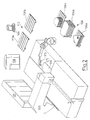
- Fig. 1 shows a functional diagram of a method for handling metal sheets in a working area (working cell), like the one indicated with 10 in Fig. 2.
- the area 10 comprises a machine tool 100 operatively connected to a processing/control unit 107, an antropomorphous robot 101 operatively connected to a control unit 108, a site 110 for feeding metal sheets to be worked and a site 106 for unloading the worked metal sheets.
- the machine tool 100 consists of a punching/shearing machine provided with a working surface 105 supporting the metal sheets being worked.
- the machine tool 100 can be of another type, for example a bending machine and such like.
- the antropomorphous robot 101 consists of an arm 102 and grasping members 103 (suction cups, device for grasping mechanically, pneumatically, magnetically and such like).
- the antropomorphous robot 101 is capable of withdrawing the worked metal sheets 104 from the working surface 105 and placing them, selected by type and stacked, on a preselected support surface 106a or 106b or 106c of the unloading site 106 that is situated within the field of action of the robot 101.
- the working area 10 also comprises an auxiliary processing unit 109 consisting, for example, of a personal computer or of a workstation, having functionalities that will be illustrated later.
- the auxiliary processing unit 109 and the control unit of the robot 108 can be incorporated, physically and functionally, in the sole processing/control unit 107 of the punching/shearing machine 100.
- a second robot that can be used for handling the metal sheets to be worked, selected by type, from a support surface 110a or 110b of the feeding site 110 to the working surface 105 of the punching/shearing machine 100.
- the method for moving of the present invention is applied to the antropomorphous robot 101 in order to execute the unloading of the worked metal sheets 104 from the surface 105 and to stack them, selected by type, in the unloading site 106.
- the method for moving, illustrated in Fig. 1 is based on a program (software algorithm) written in a preselected programming language and compiled and/or interpreted in a project computer, not shown. An executable program is obtained that is loaded into the data processing unit 109 of Fig. 2.
- the method provides for an initial step of configuration of the working area 10 (block 1 in Fig. 1) consisting in the detection of parameters that identify the geometry in the space of components that, in the case exemplified, are the antropomorphous robot 101, its grasping members 103, the working surface 105 of the punching/shearing machine 100 and the unloading site 106.
- Some parameters consist of data of position and they represent the description of the world surrounding the antropomorphous robot 101 in the form of oriented Cartesian terns (X, Y, Z, O, A, T), where (X, Y, Z) are the coordinates of the origin of the tern and (O, A, T) are the Euler angles that define the orientation of the tern in the space.
- Other parameters consist of data of the shape of the components of the working area and consist, for example, of the lengths of the arms of the robot, of the dimensions of its grasping members and of other data.
- the configuration parameters considered (block 1) consist of
- the configuration parameters indicated earlier constitute fixed input data because they are independent from the from the form and dimensions of the metal sheets 104 to be handled. They are inserted or connected in a permanent manner in the executable program resident in the data processing unit 109.
- the method also comprises a step of acquisition of variable input data (block 2) in the data processing unit 109 (Fig. 2).
- variable input data consist of
- variable input data are acquired automatically by operating programs of the punching/shearing machine 100; the step of data acquisition can be completed with the possible addition of another data consisting of
- variable input data consist of information available in any case in the processing/control unit of the punching/shearing machine for the operation of the working area. Any procedure suitable for extracting this information is capable of defining the above-mentioned variable input data and can be used for the purpose of the present invention.
- a logic/decisional algorithm establishes the initial and final points of the trajectory that the grasping members 103 of the robot 101 must perform to execute the required handling operation from the working surface 105 to a preselected support surface 106a or 106b or 106c of the unloading site 106 (block 3).
- the algorithm completes the trajectory with a series of intermediate points between the extremities calculated in this way, planned so as to constrain the robot to move along pre-established paths (block 4).
- the "point”, in this context, is a manner for representing an oriented Cartesian tern in the space and the "points" of the trajectory assume values and are sufficient in number for the motion of the robot, between two successive points, to be predictable and within the field of action of its arm.
- the method provides, for each "point" of a trajectory planned in this manner, for the calculation of (block 5):
- Inverse kinematics is a mathematical transformation that places an oriented tern of Euclidean space (X, Y, Z, O, A, T) in relation to a set of vectors Z1, Z2, Z3, ... , Zn.
- Each vector Zi has as many components as there are axes of the robot; each component represents the linear (millimetres) or angular (degrees) position that each axis can assume in order to reach the "point" (X, Y, Z, O, A, T).
- the method comprises a step of analysis of the sheet/machine interferences (block 6) for the selection of a suitable solution among those advanced in the preceding step. Particularly, interferences sheet/robot, sheet/machine tool, sheet/support surfaces are examined. This step is executed by a logical-mathematical algorithm that automatically identifies the most suitable solution, among the calculated representations, so as to eliminate the solutions that involve sheet/machine interferences, any out-of-strokes of the axes of the robot axes and improper rotations (0° and 0° ⁇ 360°) of the axes from one point to the next.
- a simplified and ergonomic graphic representation can be used that is capable of effectively visualising the sheet/machine interferences, the out-of-strokes and the improper rotations of the axes so as to select quickly (a few seconds), for all the points of the trajectory, the most suitable solution among those calculated for each point.
- This second (interactive) procedure can also be used for a quick visual check on the selections executed automatically by the first procedure.
- the method also provides for a step of generating variable output data (block 7) in a programming language specific to the control unit 108 of the robot 101.
- the results of the decisional and calculation algorithms described earlier are converted into output data valid for driving the robot 101 according to the syntax rules of its specific programming language.
- the converted data are the position vectors for the axes of the robot and a list with the sequence of the cycles to be executed.
- the method is completed with a step of generating final output data (block 8) in the form of working cycles of the robot.
- the final output data consist of a set of elementary cycles, required for executing the physical movement of the robot synchronised with the punching/shearing machine, written according to the syntax rules of the programming language of the specific robot and specifically designed to receive the variable output data described earlier (block 7).
- the combination of the elementary cycles built-up in this way and of the variable output data allows the handling operation of the metal sheets produced through the robot 101 enslaved to the punching/shearing machine 100 to be obtained automatically.
- the result is a customised software algorithm, of the executable type, that, once installed in the data processing unit 109 of the working area 10, is capable of acquiring the variable input data described earlier (block 2) and of providing at output the variable data (block 7) and the working cycles of the robot (block 8) for the automatic handling operations of the metal sheets associated with the production of the punching/shearing machine 100.
- variable data and the cycles of blocks 7 and 8 are transferred from the processing unit 109 to the control unit 108 of the robot 101 for the immediate execution of the required work.
- auxiliary processing unit 109 and the control unit of the robot 108 can be incorporated, physically and functionally, in the sole processing/control unit 107 of the punching/shearing machine 100.
- a similar method for moving can be applied to a second robot in the working area 10 for taking from the support surfaces 110a and 110b of the feeding site 110 the metal sheets to be worked, selected by type, and placing them on the working surface 105.
Landscapes
- Engineering & Computer Science (AREA)
- Mechanical Engineering (AREA)
- Robotics (AREA)
- Manipulator (AREA)
- Numerical Control (AREA)
- Bending Of Plates, Rods, And Pipes (AREA)
- Feeding Of Workpieces (AREA)
- Sheets, Magazines, And Separation Thereof (AREA)
- Multi-Process Working Machines And Systems (AREA)
- Automatic Assembly (AREA)
- Feedback Control In General (AREA)
Applications Claiming Priority (2)
| Application Number | Priority Date | Filing Date | Title |
|---|---|---|---|
| IT96MI001912A IT1284548B1 (it) | 1996-09-18 | 1996-09-18 | Metodo per trasporto di fogli di lamiera in un'isola di lavoro comprendente una macchina utensile e un robot |
| ITMI961912 | 1996-09-18 |
Publications (2)
| Publication Number | Publication Date |
|---|---|
| EP0830921A1 true EP0830921A1 (de) | 1998-03-25 |
| EP0830921B1 EP0830921B1 (de) | 2002-08-07 |
Family
ID=11374892
Family Applications (1)
| Application Number | Title | Priority Date | Filing Date |
|---|---|---|---|
| EP97202813A Expired - Lifetime EP0830921B1 (de) | 1996-09-18 | 1997-09-12 | Verfahren zur Handhabung von Blechteilen in einem Arbeitsraum mit einer Werkzeugmaschine und einem Roboter |
Country Status (11)
| Country | Link |
|---|---|
| US (1) | US6192297B1 (de) |
| EP (1) | EP0830921B1 (de) |
| JP (1) | JPH10161723A (de) |
| KR (1) | KR19980024718A (de) |
| AT (1) | ATE221817T1 (de) |
| CA (1) | CA2215742A1 (de) |
| DE (1) | DE69714534T2 (de) |
| DK (1) | DK0830921T3 (de) |
| ES (1) | ES2180887T3 (de) |
| IT (1) | IT1284548B1 (de) |
| PT (1) | PT830921E (de) |
Cited By (1)
| Publication number | Priority date | Publication date | Assignee | Title |
|---|---|---|---|---|
| GB2378672A (en) * | 2001-07-02 | 2003-02-19 | Aida Eng Ltd | Interference checking device for a transfer press |
Families Citing this family (11)
| Publication number | Priority date | Publication date | Assignee | Title |
|---|---|---|---|---|
| JP2000207004A (ja) * | 1999-01-19 | 2000-07-28 | Yukiwa Seiko Inc | Nc制御システム |
| US6938454B2 (en) * | 2002-05-13 | 2005-09-06 | Trumpf Maschinen Austria Gmbh & Co. Kg. | Production device, especially a bending press, and method for operating said production device |
| DE102004048036A1 (de) * | 2004-09-28 | 2006-04-06 | Ras Reinhardt Maschinenbau Gmbh | Biegeeinrichtung |
| JP5108260B2 (ja) * | 2006-07-06 | 2012-12-26 | 株式会社アマダ | 曲げ加工機金型レイアウトの活用方法およびその装置 |
| CN101572029B (zh) * | 2008-04-28 | 2012-01-25 | 鸿富锦精密工业(深圳)有限公司 | 机器人板材折弯模拟系统及方法 |
| US8359116B2 (en) * | 2009-09-11 | 2013-01-22 | Sap Ag | Production management system |
| US10408670B2 (en) * | 2014-12-17 | 2019-09-10 | Norgren Automation Solutions, Llc | Apparatus and method for detecting multiple workpieces |
| GB2588629B (en) * | 2019-10-29 | 2024-01-03 | Cmr Surgical Ltd | Robotic joint control |
| SE545199C2 (en) * | 2021-08-30 | 2023-05-16 | Stilride AB | Processing of a two dimensional sheet material |
| US12365083B2 (en) * | 2022-11-18 | 2025-07-22 | Zebra Technologies Corporation | Shape-memory effector systems |
| CN119304865A (zh) * | 2024-10-11 | 2025-01-14 | 大连中远海运海事工程技术有限公司 | 一种高压油泵拆装气动提升翻转机系统 |
Citations (7)
| Publication number | Priority date | Publication date | Assignee | Title |
|---|---|---|---|---|
| GB2211002A (en) * | 1987-12-15 | 1989-06-21 | Amada Co Ltd | Controlling a manipulator for a plate bending machine |
| EP0355454A2 (de) * | 1988-07-29 | 1990-02-28 | The Boeing Company | Herstellungsverfahren von Metallfolienstücken |
| WO1991008869A1 (en) * | 1989-12-18 | 1991-06-27 | Amada Company, Limited | Device for control of a robot manipulator for a metal sheet bending installation |
| WO1991010180A1 (en) * | 1989-12-22 | 1991-07-11 | Amada Company, Limited | A system for creating command and control signals for a complete operating cycle of a robot manipulator device of a sheet metal bending installation by simulating the operating environment |
| US5307282A (en) * | 1989-09-22 | 1994-04-26 | Hewlett-Packard Company | Method of computer-aided prediction of collisions between objects including fabrication tools and parts to be fabricated |
| WO1996015481A2 (en) * | 1994-11-09 | 1996-05-23 | Amada Company, Limited | Intelligent system for generating and executing a sheet metal bending plan |
| WO1996014967A1 (en) * | 1994-11-09 | 1996-05-23 | Amada Company, Limited | Method for planning/controlling robot motion |
Family Cites Families (6)
| Publication number | Priority date | Publication date | Assignee | Title |
|---|---|---|---|---|
| IT995739B (it) * | 1972-10-13 | 1975-11-20 | Schuler Gmbh L | Cescia mobile per tagliare nastro di lamiera in movimento |
| US5188135A (en) * | 1990-02-23 | 1993-02-23 | Neumann Industries, Inc. | Method and apparatus for processing sheet metal blanks and continuous strip |
| US5380055A (en) * | 1993-04-07 | 1995-01-10 | Suarez; Roderick A. | Sheet material puller |
| IT1260677B (it) * | 1993-07-29 | 1996-04-22 | Antonio Codatto | Manipolatore per la movimentazione di lastre, particolarmente pannellidi lamiera, nei confronti di una macchina operatrice, quale una pressapiegatrice. |
| US5822207A (en) * | 1996-05-06 | 1998-10-13 | Amadasoft America, Inc. | Apparatus and method for integrating intelligent manufacturing system with expert sheet metal planning and bending system |
| IT1283019B1 (it) * | 1996-05-16 | 1998-04-03 | Salvagnini Italia Spa | Metodo di gestione di un'isola di lavoro comprendente un robot asser- vito ad una pressa piegatrice per lavorazione di fogli di lamiera. |
-
1996
- 1996-09-18 IT IT96MI001912A patent/IT1284548B1/it active IP Right Grant
-
1997
- 1997-09-12 DK DK97202813T patent/DK0830921T3/da active
- 1997-09-12 EP EP97202813A patent/EP0830921B1/de not_active Expired - Lifetime
- 1997-09-12 ES ES97202813T patent/ES2180887T3/es not_active Expired - Lifetime
- 1997-09-12 PT PT97202813T patent/PT830921E/pt unknown
- 1997-09-12 DE DE69714534T patent/DE69714534T2/de not_active Expired - Lifetime
- 1997-09-12 AT AT97202813T patent/ATE221817T1/de active
- 1997-09-17 US US08/932,544 patent/US6192297B1/en not_active Expired - Lifetime
- 1997-09-17 CA CA002215742A patent/CA2215742A1/en not_active Abandoned
- 1997-09-18 KR KR1019970047582A patent/KR19980024718A/ko not_active Abandoned
- 1997-09-18 JP JP9253365A patent/JPH10161723A/ja not_active Abandoned
Patent Citations (7)
| Publication number | Priority date | Publication date | Assignee | Title |
|---|---|---|---|---|
| GB2211002A (en) * | 1987-12-15 | 1989-06-21 | Amada Co Ltd | Controlling a manipulator for a plate bending machine |
| EP0355454A2 (de) * | 1988-07-29 | 1990-02-28 | The Boeing Company | Herstellungsverfahren von Metallfolienstücken |
| US5307282A (en) * | 1989-09-22 | 1994-04-26 | Hewlett-Packard Company | Method of computer-aided prediction of collisions between objects including fabrication tools and parts to be fabricated |
| WO1991008869A1 (en) * | 1989-12-18 | 1991-06-27 | Amada Company, Limited | Device for control of a robot manipulator for a metal sheet bending installation |
| WO1991010180A1 (en) * | 1989-12-22 | 1991-07-11 | Amada Company, Limited | A system for creating command and control signals for a complete operating cycle of a robot manipulator device of a sheet metal bending installation by simulating the operating environment |
| WO1996015481A2 (en) * | 1994-11-09 | 1996-05-23 | Amada Company, Limited | Intelligent system for generating and executing a sheet metal bending plan |
| WO1996014967A1 (en) * | 1994-11-09 | 1996-05-23 | Amada Company, Limited | Method for planning/controlling robot motion |
Cited By (3)
| Publication number | Priority date | Publication date | Assignee | Title |
|---|---|---|---|---|
| GB2378672A (en) * | 2001-07-02 | 2003-02-19 | Aida Eng Ltd | Interference checking device for a transfer press |
| GB2378672B (en) * | 2001-07-02 | 2004-12-15 | Aida Eng Ltd | Interference checking device for a transfer press |
| US6845646B2 (en) | 2001-07-02 | 2005-01-25 | Aida Engineering Co., Ltd. | Interference checking device for a transfer press |
Also Published As
| Publication number | Publication date |
|---|---|
| DE69714534D1 (de) | 2002-09-12 |
| JPH10161723A (ja) | 1998-06-19 |
| KR19980024718A (ko) | 1998-07-06 |
| US6192297B1 (en) | 2001-02-20 |
| ATE221817T1 (de) | 2002-08-15 |
| PT830921E (pt) | 2002-12-31 |
| ES2180887T3 (es) | 2003-02-16 |
| EP0830921B1 (de) | 2002-08-07 |
| CA2215742A1 (en) | 1998-03-18 |
| ITMI961912A1 (it) | 1998-03-18 |
| IT1284548B1 (it) | 1998-05-21 |
| DK0830921T3 (da) | 2002-12-02 |
| DE69714534T2 (de) | 2003-05-15 |
Similar Documents
| Publication | Publication Date | Title |
|---|---|---|
| US5988855A (en) | Operating method for a working area comprising a robot enslaved to a bending press for working metal sheets | |
| Torgerson et al. | Vision-guided robotic fabric manipulation for apparel manufacturing | |
| US6192297B1 (en) | Method for handling metal sheets in a working area comprising a machine tool and a robot | |
| Kim | CAD‐based automated robot programming in adhesive spray systems for shoe outsoles and uppers | |
| CN109129413B (zh) | 显示速度的机器人系统 | |
| Pedrocchi et al. | Design of fuzzy logic controller of industrial robot for roughing the uppers of fashion shoes | |
| CN113763462A (zh) | 一种自动化控制上料的方法及系统 | |
| CN110914021A (zh) | 带有用于执行至少一个工作步骤的操纵设备的操纵装置以及方法和计算机程序 | |
| WO2020231319A1 (en) | Robot cell setup system and process | |
| FI112922B (fi) | Menetelmä työstökonesolun ohjauksessa | |
| Basanez et al. | Robotic polishing systems | |
| WO2021185805A2 (en) | A relocatable robotic system for production facilities | |
| US11897142B2 (en) | Method and device for creating a robot control program | |
| Wang et al. | Research on trajectory planning algorithm for intelligence robot cutting-grinding | |
| Filaretov et al. | Human machine interface based on virtual reality for programming industrial robots | |
| US12017371B2 (en) | Efficient and robust line matching approach | |
| Lindberget | Automatic generation of robot targets: A first step towards a flexible robotic solution for cutting customized mesh tray | |
| Neto et al. | 3D CAD-based robot programming for the SME shop-floor | |
| Le et al. | Self adaptive system for flexible robot assembly operation | |
| Shneor et al. | Robotic Assembly with deformable objects | |
| Mabrouk et al. | Offline programming with intelligent vision system of KUKA robot | |
| Yukhimets et al. | Development of method for generating trajectories of movement of end effectors and control programs for industrial robots in an uncertain working environment | |
| Winkler | Intuitive visual definition of part aligned coordinate systems and mo-tions for industrial robots | |
| JPH1190873A (ja) | 工作機械及びロボットが備えられた作業エリアにおける金属板の取扱方法 | |
| Earl et al. | Sheet Metal Enclosure Manufacture—A Flexible System |
Legal Events
| Date | Code | Title | Description |
|---|---|---|---|
| PUAI | Public reference made under article 153(3) epc to a published international application that has entered the european phase |
Free format text: ORIGINAL CODE: 0009012 |
|
| AK | Designated contracting states |
Kind code of ref document: A1 Designated state(s): AT BE CH DE DK ES FI FR GB GR IE IT LI LU NL PT SE |
|
| 17P | Request for examination filed |
Effective date: 19980915 |
|
| AKX | Designation fees paid |
Free format text: AT BE CH DE DK ES FI FR GB GR IE IT LI LU NL PT SE |
|
| RBV | Designated contracting states (corrected) |
Designated state(s): AT BE CH DE DK ES FI FR GB GR IE IT LI LU NL PT SE |
|
| 17Q | First examination report despatched |
Effective date: 20000911 |
|
| GRAG | Despatch of communication of intention to grant |
Free format text: ORIGINAL CODE: EPIDOS AGRA |
|
| GRAG | Despatch of communication of intention to grant |
Free format text: ORIGINAL CODE: EPIDOS AGRA |
|
| GRAH | Despatch of communication of intention to grant a patent |
Free format text: ORIGINAL CODE: EPIDOS IGRA |
|
| GRAH | Despatch of communication of intention to grant a patent |
Free format text: ORIGINAL CODE: EPIDOS IGRA |
|
| GRAH | Despatch of communication of intention to grant a patent |
Free format text: ORIGINAL CODE: EPIDOS IGRA |
|
| GRAA | (expected) grant |
Free format text: ORIGINAL CODE: 0009210 |
|
| AK | Designated contracting states |
Kind code of ref document: B1 Designated state(s): AT BE CH DE DK ES FI FR GB GR IE IT LI LU NL PT SE |
|
| PG25 | Lapsed in a contracting state [announced via postgrant information from national office to epo] |
Ref country code: GR Free format text: LAPSE BECAUSE OF FAILURE TO SUBMIT A TRANSLATION OF THE DESCRIPTION OR TO PAY THE FEE WITHIN THE PRESCRIBED TIME-LIMIT Effective date: 20020807 |
|
| REF | Corresponds to: |
Ref document number: 221817 Country of ref document: AT Date of ref document: 20020815 Kind code of ref document: T |
|
| REG | Reference to a national code |
Ref country code: GB Ref legal event code: FG4D |
|
| REG | Reference to a national code |
Ref country code: CH Ref legal event code: EP |
|
| REG | Reference to a national code |
Ref country code: IE Ref legal event code: FG4D |
|
| PG25 | Lapsed in a contracting state [announced via postgrant information from national office to epo] |
Ref country code: LU Free format text: LAPSE BECAUSE OF NON-PAYMENT OF DUE FEES Effective date: 20020912 Ref country code: IE Free format text: LAPSE BECAUSE OF NON-PAYMENT OF DUE FEES Effective date: 20020912 |
|
| REF | Corresponds to: |
Ref document number: 69714534 Country of ref document: DE Date of ref document: 20020912 |
|
| REG | Reference to a national code |
Ref country code: CH Ref legal event code: NV Representative=s name: E. BLUM & CO. PATENTANWAELTE |
|
| PGFP | Annual fee paid to national office [announced via postgrant information from national office to epo] |
Ref country code: PT Payment date: 20021202 Year of fee payment: 6 |
|
| REG | Reference to a national code |
Ref country code: DK Ref legal event code: T3 |
|
| REG | Reference to a national code |
Ref country code: PT Ref legal event code: SC4A Free format text: AVAILABILITY OF NATIONAL TRANSLATION Effective date: 20021106 |
|
| REG | Reference to a national code |
Ref country code: ES Ref legal event code: FG2A Ref document number: 2180887 Country of ref document: ES Kind code of ref document: T3 |
|
| ET | Fr: translation filed | ||
| PLBE | No opposition filed within time limit |
Free format text: ORIGINAL CODE: 0009261 |
|
| STAA | Information on the status of an ep patent application or granted ep patent |
Free format text: STATUS: NO OPPOSITION FILED WITHIN TIME LIMIT |
|
| REG | Reference to a national code |
Ref country code: IE Ref legal event code: MM4A |
|
| 26N | No opposition filed |
Effective date: 20030508 |
|
| PG25 | Lapsed in a contracting state [announced via postgrant information from national office to epo] |
Ref country code: PT Free format text: LAPSE BECAUSE OF NON-PAYMENT OF DUE FEES Effective date: 20040331 |
|
| REG | Reference to a national code |
Ref country code: PT Ref legal event code: MM4A Free format text: LAPSE DUE TO NON-PAYMENT OF FEES Effective date: 20040331 |
|
| REG | Reference to a national code |
Ref country code: CH Ref legal event code: PFA Owner name: SALVAGNINI ITALIA S.P.A. Free format text: SALVAGNINI ITALIA S.P.A.#VIA MONTICELLO DI FARA, 42#I-36040 SAREGO (VICENZA) (IT) -TRANSFER TO- SALVAGNINI ITALIA S.P.A.#VIA MONTICELLO DI FARA, 42#I-36040 SAREGO (VICENZA) (IT) |
|
| PGFP | Annual fee paid to national office [announced via postgrant information from national office to epo] |
Ref country code: NL Payment date: 20100824 Year of fee payment: 14 Ref country code: ES Payment date: 20100906 Year of fee payment: 14 Ref country code: CH Payment date: 20100824 Year of fee payment: 14 |
|
| PGFP | Annual fee paid to national office [announced via postgrant information from national office to epo] |
Ref country code: SE Payment date: 20100824 Year of fee payment: 14 Ref country code: IT Payment date: 20100904 Year of fee payment: 14 Ref country code: FI Payment date: 20100823 Year of fee payment: 14 Ref country code: AT Payment date: 20100823 Year of fee payment: 14 |
|
| PGFP | Annual fee paid to national office [announced via postgrant information from national office to epo] |
Ref country code: GB Payment date: 20100826 Year of fee payment: 14 |
|
| PGFP | Annual fee paid to national office [announced via postgrant information from national office to epo] |
Ref country code: FR Payment date: 20101018 Year of fee payment: 14 Ref country code: DK Payment date: 20100824 Year of fee payment: 14 |
|
| PGFP | Annual fee paid to national office [announced via postgrant information from national office to epo] |
Ref country code: DE Payment date: 20100909 Year of fee payment: 14 Ref country code: BE Payment date: 20100825 Year of fee payment: 14 |
|
| BERE | Be: lapsed |
Owner name: *SALVAGNINI ITALIA S.P.A. Effective date: 20110930 |
|
| REG | Reference to a national code |
Ref country code: NL Ref legal event code: V1 Effective date: 20120401 |
|
| REG | Reference to a national code |
Ref country code: CH Ref legal event code: PL Ref country code: DK Ref legal event code: EBP |
|
| GBPC | Gb: european patent ceased through non-payment of renewal fee |
Effective date: 20110912 |
|
| PG25 | Lapsed in a contracting state [announced via postgrant information from national office to epo] |
Ref country code: FI Free format text: LAPSE BECAUSE OF NON-PAYMENT OF DUE FEES Effective date: 20110912 Ref country code: IT Free format text: LAPSE BECAUSE OF NON-PAYMENT OF DUE FEES Effective date: 20110912 |
|
| REG | Reference to a national code |
Ref country code: FR Ref legal event code: ST Effective date: 20120531 |
|
| PG25 | Lapsed in a contracting state [announced via postgrant information from national office to epo] |
Ref country code: BE Free format text: LAPSE BECAUSE OF NON-PAYMENT OF DUE FEES Effective date: 20110930 |
|
| REG | Reference to a national code |
Ref country code: SE Ref legal event code: EUG |
|
| REG | Reference to a national code |
Ref country code: DE Ref legal event code: R119 Ref document number: 69714534 Country of ref document: DE Effective date: 20120403 |
|
| PG25 | Lapsed in a contracting state [announced via postgrant information from national office to epo] |
Ref country code: NL Free format text: LAPSE BECAUSE OF NON-PAYMENT OF DUE FEES Effective date: 20120401 Ref country code: CH Free format text: LAPSE BECAUSE OF NON-PAYMENT OF DUE FEES Effective date: 20110930 Ref country code: LI Free format text: LAPSE BECAUSE OF NON-PAYMENT OF DUE FEES Effective date: 20110930 Ref country code: DE Free format text: LAPSE BECAUSE OF NON-PAYMENT OF DUE FEES Effective date: 20120403 |
|
| PG25 | Lapsed in a contracting state [announced via postgrant information from national office to epo] |
Ref country code: FR Free format text: LAPSE BECAUSE OF NON-PAYMENT OF DUE FEES Effective date: 20110930 Ref country code: GB Free format text: LAPSE BECAUSE OF NON-PAYMENT OF DUE FEES Effective date: 20110912 |
|
| PG25 | Lapsed in a contracting state [announced via postgrant information from national office to epo] |
Ref country code: DK Free format text: LAPSE BECAUSE OF NON-PAYMENT OF DUE FEES Effective date: 20110930 |
|
| REG | Reference to a national code |
Ref country code: AT Ref legal event code: MM01 Ref document number: 221817 Country of ref document: AT Kind code of ref document: T Effective date: 20110912 |
|
| PG25 | Lapsed in a contracting state [announced via postgrant information from national office to epo] |
Ref country code: AT Free format text: LAPSE BECAUSE OF NON-PAYMENT OF DUE FEES Effective date: 20110912 |
|
| PG25 | Lapsed in a contracting state [announced via postgrant information from national office to epo] |
Ref country code: SE Free format text: LAPSE BECAUSE OF NON-PAYMENT OF DUE FEES Effective date: 20110913 |
|
| REG | Reference to a national code |
Ref country code: ES Ref legal event code: FD2A Effective date: 20130606 |
|
| PG25 | Lapsed in a contracting state [announced via postgrant information from national office to epo] |
Ref country code: ES Free format text: LAPSE BECAUSE OF NON-PAYMENT OF DUE FEES Effective date: 20110913 |