EP0831427A2 - Ein- und Ausfahrtkontrollstation für kostenpflichtige Parkplätze - Google Patents
Ein- und Ausfahrtkontrollstation für kostenpflichtige Parkplätze Download PDFInfo
- Publication number
- EP0831427A2 EP0831427A2 EP97116135A EP97116135A EP0831427A2 EP 0831427 A2 EP0831427 A2 EP 0831427A2 EP 97116135 A EP97116135 A EP 97116135A EP 97116135 A EP97116135 A EP 97116135A EP 0831427 A2 EP0831427 A2 EP 0831427A2
- Authority
- EP
- European Patent Office
- Prior art keywords
- control station
- parking
- entry
- exit control
- station according
- Prior art date
- Legal status (The legal status is an assumption and is not a legal conclusion. Google has not performed a legal analysis and makes no representation as to the accuracy of the status listed.)
- Granted
Links
Images



Classifications
-
- G—PHYSICS
- G07—CHECKING-DEVICES
- G07B—TICKET-ISSUING APPARATUS; FARE-REGISTERING APPARATUS; FRANKING APPARATUS
- G07B15/00—Arrangements or apparatus for collecting fares, tolls or entrance fees at one or more control points
- G07B15/02—Arrangements or apparatus for collecting fares, tolls or entrance fees at one or more control points taking into account a variable factor such as distance or time, e.g. for passenger transport, parking systems or car rental systems
- G07B15/04—Arrangements or apparatus for collecting fares, tolls or entrance fees at one or more control points taking into account a variable factor such as distance or time, e.g. for passenger transport, parking systems or car rental systems comprising devices to free a barrier, turnstile, or the like
-
- G—PHYSICS
- G07—CHECKING-DEVICES
- G07F—COIN-FREED OR LIKE APPARATUS
- G07F17/00—Coin-freed apparatus for hiring articles; Coin-freed facilities or services
- G07F17/14—Coin-freed apparatus for hiring articles; Coin-freed facilities or services for fastenings for doors; for turnstiles
- G07F17/145—Coin-freed apparatus for hiring articles; Coin-freed facilities or services for fastenings for doors; for turnstiles for revolving doors or turnstiles
-
- Y—GENERAL TAGGING OF NEW TECHNOLOGICAL DEVELOPMENTS; GENERAL TAGGING OF CROSS-SECTIONAL TECHNOLOGIES SPANNING OVER SEVERAL SECTIONS OF THE IPC; TECHNICAL SUBJECTS COVERED BY FORMER USPC CROSS-REFERENCE ART COLLECTIONS [XRACs] AND DIGESTS
- Y10—TECHNICAL SUBJECTS COVERED BY FORMER USPC
- Y10S—TECHNICAL SUBJECTS COVERED BY FORMER USPC CROSS-REFERENCE ART COLLECTIONS [XRACs] AND DIGESTS
- Y10S194/00—Check-actuated control mechanisms
- Y10S194/902—Check-operated device for controlling parking lot
Definitions
- the invention relates to an entry and exit control station for fee-based Parking lots with an entrance-side dispenser for disc-shaped parking tickets and an exit-side return device for this, each with one of the dispensing and return devices assigned reading device and with at least one control device for a user-specific issue and return of parking tickets.
- the dispenser is in stock the parking tickets in a storage container and give at the beginning of a parking process Parking tickets from this storage container to individual users out. If the stored parking tickets are repeated issuable parking tickets with an identification and / or communication element, this is how they are returned at the end of a parking process Parking tickets collected in a return container. As soon as the return container full or filled with a predetermined amount of parking tickets is manually emptied by the returned parking tickets poured back into the storage container of the dispenser will. This process of decanting is not only complex and must be done always be repeated, but often also with insufficient Vote on the fill level of the storage container carried out so that this can run empty and therefore no longer the entrance to a parking garage is possible.
- a device for the individual output of disc-shaped objects in which a stack of layers Objects on a forward inclined and upward moving Floor slide is arranged.
- the disc-shaped objects are supported on the front against a surface, the one side discharge opening for the exit of one object at a time having.
- the stack is lifted by means of the floor slide move against a sensor on the head side, which prevents the Stack up to the orientation of the topmost object of the stack controls, so that then the uppermost under gravity Object of the stack through the discharge opening and with separation slides from the stack into an output tray.
- Such a device requires the formation of stacking columns, reducing the intake amount limited to objects.
- the bottom slide repeated with new stacks of stacked objects to be equipped, for which the bottom slide always in its starting position must be moved back. A continuous release of disc-shaped objects is therefore not with this device possible.
- the object of the invention is therefore an entry and exit control station according to the preamble of claim 1 to create the repatriation used parking tickets for reissue and simplified prevents the entry-side dispenser from running empty.
- This task is characterized by the characteristics of the characteristic part of the Claim 1 solved.
- This creates an entry and exit control station at the the return of the used parking tickets to the entrance-side dispenser is automated.
- the issue and return device the entrance and exit control station are via a parking ticket return device connected with each other, without expensive transportation and Grants.
- the parking tickets to be returned are in a pushing unit moves through a transport channel, which has a spatial Distance between the dispenser and the take-back device bridged.
- a spatial Distance between the dispenser and the take-back device bridged.
- the peripheral surface preferably has Parking tickets with a width of 2 to 8 mm.
- Parking tickets are also used as parking tickets disc-shaped, round parking tickets are used, so a push bandage can formed from parking tickets contacting one another over the peripheral surfaces be, while using a rolling ability of the Park tickets can move forward.
- the parking lot return device can be in a combined entry and exit control station be installed, or if the entrance control station is physically separate from the exit control station, either in one way or another in conjunction with an additional one if necessary Connection channel or built into both stations be as set out in claims 3 to 7.
- the entry and exit control station can be spaced apart Ascent section as at least a section of a transfer channel between Entry and exit control station can be used.
- the parking ticket return device can comprise buffer or storage containers or shafts, from or into which Thrust device promotes.
- the output device can thus be detached from a single parking ticket return for a needs-based Issue.
- either Dispensing device upstream of a storage container or channel which the parking lot return device promotes, and / or the return device such a storage container or channel can be arranged downstream, from which the parking lot return device can then convey.
- the delivery and return device can each have a chute comprise, along each of which a reading and possibly communication device is arranged.
- a lock to hold one temporarily Parking tickets in this reading and, if applicable, communication area can also be provided for a longer stay of a parking ticket to achieve in this functional area.
- the at least one Control device can detect a withdrawal and issue of Parking tickets can be linked to the actuation of a parking barrier. Further can operate the thrust device by means of the control device depending on the issue or redemption of a parking ticket being controlled.
- the pushing device is preferably designed according to claims 15 to 20.
- the design of the thrust device as a drive plate enables that the pusher not only moves the parking tickets forward, but also isolated in advance. Additional separation devices are avoided. The result is a structurally simple one Construction that is also not susceptible to maintenance. Furthermore, on the drive plate Guide bars are attached in such a way that in a riser supported parking tickets are held by support, and until a subsequently supported parking ticket through the Thrust device is moved forward into the riser and there parked or standing parking tickets. This design too allows a structurally simple construction.
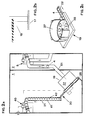
- the first embodiment of an input and Exit control station for paid parking spaces includes one Entry control station 1 and an exit control station 2, all in one common housing 3 or installed in adjacent housing are.
- the first exemplary embodiment accordingly relates to a combined one Entry and exit control station, the reusable parking tickets 4 issues and withdraws.
- the parking tickets 4 are essentially disc-shaped parking tickets rigid or rigid material, especially plastic.
- the outer shape of the parking ticket 4 can be selected. However, round ones are preferred Parking tickets 4, since their rolling ability improves eligibility.
- the thickness of the parking tickets 4 or their edge design is selected such that that the parking tickets have a peripheral running and contact surface, which has a width of 2 to 8 mm. Also in the parking tickets 4 an identification element and possibly a communication element with a selectable identifier installed by the entry and exit control station can be read.
- the exit control station 2 comprises a return device on the exit side 5, which includes a chute 6.
- the chute 6 goes from a parking ticket entry opening 7, which is in an exit-side Housing wall 8 is located, and has such dimensions that the parking tickets 4 standing or rolling the chute 6 on its circumferential surface can slide down and cannot fall over from this position.
- a floor surface 9 of the chute 6 then forms for the parking tickets 4 a tread.
- a reading and optionally provided communication device 11 At an initial section 10 of the chute 6 is a reading and optionally provided communication device 11, by means of a Thrown by an outgoing user through the input opening 7 Park ticket 4 read and if necessary described.
- the reading and optionally communication device 11 can be in a known manner from a read head, possibly combined with a write head will.
- the reading and possibly communication device 11 is connected to a control device 12 which read values for Activation of further devices that can be connected to the control device 11 processed.
- a lock 13 is provided with the the chute 6 can be closed or released to the parking tickets 4 for a selectable period of time in the range of effect of the reading and possibly communication device 11.
- the direction the displaceability of the lock 13 is marked by a double arrow.
- the position of the lock 13 in the release position is dashed shown, the position of the lock 13 in the blocking position is shown with solid lines. To operate the lock 13 it is connected to the control device 12.
- the return device 5 can further comprise a return chute 14, the downstream of the reading and possibly communication device 11 branches off from the chute 6 and to a return opening 15 runs in the exit-side housing wall 8. From the reading and possibly Communication device 11 as not authorized to exit Parking tickets 4 can be returned to one via this return chute 14 Users are returned.
- a rocker or a cross pin 16 is provided, the one or the Swivel range in and out of the chute 6 marked by a double arrow is.
- the rocker 16 is actuated via the control device 12 triggered, for which it is connected to the control device 12.
- a lane 17 can also be connected to the control device 12 crossing parking barrier 18 (see FIG. 1b) to be connected To open and close.
- the control device can also a checkout station, not shown, may be connected to this the exit authorization for a parking ticket 4, especially marked to get signaled by its identifier.
- At least one pushing device is arranged downstream of the return device 5 19 belonging to a parking ticket return device 20 which the return device 5 with an entry-side dispensing device 40 connects.
- the parking lot return device 20 includes in addition to the at least one thrust device 19 a transport channel 21, the an inlet 22 to an outlet 23 of the pusher 19 and with an outlet 24 connects to the entrance-side dispenser 21. Characterized in that the chute 6 connects to the thrust device 19 and thus the parking tickets 4 of the pusher returned by the users 19 supplies, this can the recorded parking tickets 4 in the Promote transport channel 21, the parking tickets to the entrance Output device 40 conducts.
- the pushing device 19 is preferably formed by a drive plate, as shown in Fig. 1c.
- the drive plate includes a combined Parking ticket separation and driver device 26 and a patch Storage container 27 for receiving a plurality of parking tickets 4.
- the parking ticket separation and driver device 26 forms a bottom of the storage container 27.
- the parking ticket separation and -Driving device comprises a parking ticket catch disc by a Perforated disc 28 (see FIGS. 4 and 5) is formed, which is rotatable over a Guide track 29 (see FIGS. 6 and 7) mounted and by means of a motor 30 can be driven continuously or step by step.
- the perforated disk has 28 a plurality of concentrically arranged holes 31. Since according to the described Exemplary round parking tickets 4 are used, the holes 31 are round recesses whose diameters slightly exceeds the diameter of the parking tickets 4 the parking tickets 4 slide into and through the holes 31 the underlying guideway 29 can fall.
- the perforated disc 28 1c differs from the perforated disk 28 according to FIG. 4 only with respect to the number of holes 31. Otherwise, the perforated disks are 28 constructed the same way, so that with regard to the detailed description on the in the Figures 4 and 5 shown perforated disc 28 is referenced.
- the perforated disk 28 has projecting projections on the rear Guide webs 32 with which the perforated disc 28 in the Guideway 29 engages.
- the guide webs 32 surround each hole 31 like a mouth with a circumferential one Jaw opening 33 through which a parking ticket 4 is carried out can.
- a parking ticket 4 caught by a hole 31 therefore fails the hole 31 through into the guide track 29 arranged below and upon rotation of the perforated disk 28 in the direction of an outlet 23 from the jaws 32 surrounding the respective hole 31 in the area of the respective hole 31 held and moved.
- the sense of rotation depends on the selectable direction of the output 23.
- the guideway 29 ends in one Exit 23, which is formed by an arch exit and one straight here Spout forms.
- This output 23 has lateral boundary edges 35, 36 for a positive guidance of the in the guideway 29 running parking tickets in the exit 23. Due to the rotating movement of the Perforated disk 28 and the positive guidance in the output 23 are those in the Guided parking ticket 4 through the mouth opening 33 from the Perforated disk 28 moved out.
- the guide track 29 thus has a loop-like shape, with a Loop arch 37 arranged on the circular arc of the arrangement of the holes 31 and a dead end 38 on a selectable bow section is provided, this dead end 38 is selected so that the bow 37, which is the catch route for the parking tickets 4 in the storage container 27 and thus for the separation of the parking tickets 4 is long as possible. 6, the dead end 38 is adjacent to exit 23.
- the rear projecting surround Guide webs 32 the holes 31 not only mouth-like, but also include edge-side, parallel to the peripheral surface between each two mouth webs 34 running second guide webs 39.
- These second Guide webs 39 form thrust and support surfaces for one of each Perforated disc 28 in the exit 23 promoted parking ticket 4.
- the parking tickets 4 are in succession from the perforated disc 28 in the exit 23 and from there into the Transport channel 21 moves.
- the second guide webs 39 cause a in the exit 23 moving parking ticket 4 with a further rotation of the Perforated disc 28 receives a thrust movement for a forward movement and is also supported.
- the pushing device 19 has a perforated disc 28, which is erected inclined upright, as shown in Fig. 1a. This will catch the parking tickets 4 through the perforated disc 28 and thus simplifying their separation. Furthermore, the Output 23 are arranged at the top of the pusher 19 and a Form kind of chute, which improves the structure of the shear bandage 41.
- the transport channel 21 adjoining the pushing device 19 closes with at least one riser 42 to the output 23 of the thrust device 19 in which the pushing unit 41 moves forward.
- the ascent distance reached is preferably selected in such a way that the outlet 24 of the transport channel the returned parking tickets 4 transfers to the output device 40 at a height level, that the parking tickets 4 via a provided in the output device 40 Fall chute 43 can be issued.
- This chute 43 ends into an entry-exit opening 44 in the entrance-side housing wall 45, preferably the dispensing opening 44 and the return opening 7 in FIG the same user-friendly height.
- the cross section of the transport channel 21 is selected so that this Parking tickets in an upright, rollable position, as in Fig. 1a is shown.
- the length guide of the transort channel 21 is selectable, sections with different heights can be combined are. Curve sections can also be included.
- the output device 40 is equipped, similarly to the back frame device 5, with a reading and possibly communication device 46, by means of which a parking ticket 4 to be issued by an incoming user by pressing a call button 47 is read and, if necessary, written.
- the reading and possibly communication device 46 can be formed in a known manner by a reading head, optionally combined with a writing head.
- the reading and possibly communication device 46 is connected to a control device 48, which processes the read values for controlling further devices that can be connected to the control device 48.
- a lock 49 Downstream of the point where the reading and possibly communication device 46 is arranged, a lock 49 is provided with which the chute 43 can be closed or released in order to issue a parking ticket 4 only on demand.
- the direction of the displaceability of the lock 49 is marked by a double arrow.
- the position of the lock 49 in the release position is shown in dashed lines, the position of the lock 49 in the blocking position is shown with solid lines. To actuate the lock 49, it is connected to the control device 48.
- the control devices 12, 48 can form a common control device be summarized.
- the control device 48 of the output device 40 also the drive 30 for actuating the pushing device 19 is connected.
- Thruster 19 actuated and new parking tickets from the return device 5 can be returned to the output device 40.
- the chute 43 of the output device 40 can be a level monitor 50 may be provided, which is also connected to the control device 48 is.
- the return of the parking tickets 4, the return of Operation of the pusher 19 and the issuance of the parking tickets can be coordinated so that a continuous Pass of the parking tickets 4 is reached.
- the interposition of Buffer sections and / or storage containers, in particular the storage container 27 of the thrust device 19 increases the flexibility of the system.
- a dispenser can be arranged in front of the dispensing device 40 be in which the parking lot return device 20 promotes and out the issuing device 40 removes parking tickets to be issued as required.
- the entry and exit control station described works as follows: A parking customer who wants to exit at the end of a parking process throws his parking ticket 4 authorizing the exit into the exit entry opening 7, whereby it gets into the chute 6 of the return device 5. At the reading and possibly communication device read the parking ticket 4, especially its ID. Lies for this Identification of the control device 12 before an exit authorization, so the parking barrier 18 is opened and the withdrawn parking ticket falls over the chute 6 in the pusher, and initially in the mounted reservoir 27, at which the chute 6 ends.
- the parking lot return device is used as required from this storage container 27 20 withdrawn parking tickets individually and in one forward-moving shear bandage overcoming a height difference to the dispenser 40, from where the returned parking tickets 4 can be re-issued as required.
- Figures 2a to 2c show a second embodiment of the Einund Exit control station that differs from the one just described differs in that the entrance control station 1 spatially can be set up separately from the exit control station 2.
- the Parking ticket return device 20 with pusher 19 and transport channel 21 is then preferably installed in the entrance control station 1.
- the connection between the return device 5 and the pusher 19 takes place with the interposition of a connecting channel 51, the spatial distances between the entry and exit control station can bridge.
- the connecting channel 51 preferably runs with a Slope from one to the other station 1, 2, so that alone under The parking ticket 4 can be moved through the connecting channel 51 by the action of gravity are.
- the connecting channel 51 preferably has the same cross section like the chute 6 of the take-back device 5, to which it is connected with a Starts at the beginning.
- the end of the connecting channel 51 connects to the Thruster 19 on. Otherwise, the explanations for the figures apply 1a to 1c.
- the parking barrier 18 according to FIG. 1b and the pushing device 19 according to FIG. 1c correspond to those of FIGS. 2b and 2c.
- Figures 3a to 3c show a third embodiment of the inputs and Exit control station 1, 2, which is different from the first embodiment according to Figures 1a to 1c differs in that the entrance control station 1 spatially separated from the exit control station stands and as in the second embodiment, an additional spatial distance bridging connecting device is provided.
- the entry control stations are for this purpose 1 and the exit control station 2 each with a parking ticket return device 20, 20 '' from pusher 19, 19 '' and Transport channel 21, 21 "equipped, the transport channel 21" of Exit control station directly to the pushing device 19 of the entrance control station or with the interposition of an additional connection channel 51 ''.
- FIGS. 1a to 1c apply correspondingly for the third embodiment according to Figures 3a to 3c. Those marked with a double line at the reference symbols Components are the same as those with the same reference numbers without double dashes educated.
- the entrance control station the parking lot return device 20 is omitted and the transport channel 21 '' of the exit control station the parking tickets to such a height level promote that from there at least slightly downhill Connection channel the output device 40 of the entrance control station 1 fed directly with returned parking tickets becomes.
Landscapes
- Physics & Mathematics (AREA)
- General Physics & Mathematics (AREA)
- Business, Economics & Management (AREA)
- Finance (AREA)
- Devices For Checking Fares Or Tickets At Control Points (AREA)
Abstract
Description
- Fig. 1a
- zeigt schematisch und teilweise geschnitten eine Vorderansicht eines ersten Ausführungsbeispiels einer Ein- und Ausfahrtkontrollstation,
- Fig. 1b
- zeigt schematisch eine der Ein- und Ausfahrtkontrollstation gemäß Fig. 1a zuschaltbare Parkschranke,
- Fig. 1c
- zeigt schematisch eine seitliche Vorderansicht der Schubeinrichtung gemäß Fig. 1a,
- Fig. 2a
- zeigt schematisch und teilweise geschnitten eine Vorderansicht eines zweiten Ausführungsbeispiels einer Ein- und Ausfahrtkontrollstation,
- Fig. 2b
- zeigt schematisch eine der Ein- und Ausfahrtkontrollstation gemäß Fig. 2a zuschaltbare Parkschranke,
- Fig. 2c
- zeigt schematisch eine seitliche Vorderansicht der Schubeinrichtung gemäß Fig. 2a,
- Fig. 3a
- zeigt schematisch und teilweise geschnitten eine Vorderansicht eines dritten Ausführungsbeispiels einer Ein- und Ausfahrtkontrollstation,
- Fig. 3b
- zeigt schematisch eine der Ein- und Ausfahrtkontrollstation gemäß Fig. 3a zuschaltbare Parkschranke,
- Fig. 3c
- zeigt schematisch eine seitliche Vorderansicht der Schubeinrichtung gemäß Fig. 3a,
- Fig. 4
- zeigt eine Unteransicht einer Parkticketfang- und -treiberscheibe,
- Fig. 5
- zeigt einen Schnitt gemäß B-B der Fig. 4,
- Fig. 6
- zeigt eine Draufsicht einer Führungsbahn einer Schubeinrichtung, die mit der Parkticketfang- und treiberscheibe gemäß Fig. 4 zusammenarbeitet,
- Fig. 7
- zeigt einen Schnitt gemäß A-A der Fig. 6.
Flußabwärts der Stelle, wo die Lese- und gegebenenfalls Kommunikationsvorrichtung 46 angeordnet ist, ist eine Sperre 49 vorgesehen, mit der der Fallschacht 43 geschlossen oder freigegeben werden kann, um jeweils ein Parkticket 4 nur auf Abruf auszugeben. Die Richtung der Verschiebbarkeit der Sperre 49 ist durch einen Doppelpfeil markiert. Die Stellung der Sperre 49 in der Freigabestellung ist gestrichelt dargestellt, die Stellung der Sperre 49 in der Blockierstellung ist mit durchgezogenen Linien dargestellt. Zur Betätigung der Sperre 49 ist diese an die Steuervorrichtung 48 angeschlossen.
Claims (21)
- Ein- und Ausfahrtkontrollstation für gebührenpflichtige Parkplätze mit einer einfahrtseitigen Ausgabevorrichtung für scheibenförmige Parktickets und einer ausfahrtseitigen Rücknahmevorrichtung für diese, mit jeweils einer der Ausgabe- und der Rücknahmevorrichtung zugeordneten Lesevorrichtung und mit mindestens einer Steuereinrichtung für eine benutzerbezogene Ausgabe und Rücknahme von Partickets, dadurch gekennzeichnet, daß die Ausgabe- und Rücknahmevorrichtung (40, 5) aneinandergekoppelt sind über eine Parkticketrückführvorrichtung (20), die einen mit einem Auslaß (24) an die Ausgabevorrichtung (40) anschließenden, die Parktickets (4) führenden Transportkanal (21) und mindestens eine der Rücknahmevorrichtung (5) nachgeordnete Schubeinrichtung (19) umfaßt, und der Transportkanal (21) mit mindestens einer Steigstrecke (42) an einen Ausgang (23) der Schubeinrichtung (19) anschließt zur Aufnahme eines Verbandes (41) aus unter Schwerkraftwirkung übereinanderliegender Parktickets (4), gegen die von der Schubeinrichtung (19) aufgenommene, eine Schubbewegung auf das jeweilig unterste Reihenglied ausübende Parktickets (4) in und mittels eines Parkticket-Massenstroms durch den Transportkanal (21) förderbar sind.
- Ein- und Ausfahrtkontrollstation nach Anspruch 1, dadurch gekennzeichnet, daß die Parkticketrückführvorrichtung (20) in eine kombinierte Ein- und Ausfahrtkontrollstation (1, 2) eingebaut ist.
- Ein- und Ausfahrtkontrollstation nach Anspruch 1, dadurch gekennzeichnet, daß die Einfahrtkontrollstation (1) eine selbständige Baueinheit ist, in die der Transportkanal (21) und die Schubeinrichtung (19) integriert sind, und die Schubeinrichtung (19) über einen einen räumlichen Abstand zwischen der Einfahrtkontrollstation (1) und der Ausfahrtkontrollstation (1) überbrückenden Verbindungskanal (51) an die Rücknahmevorrichtung (5) angeschlossen ist.
- Ein- und Ausfahrtkontrollstation nach Anspruch 3, dadurch gekennzeichnet, daß der Verbindungskanal (51) mit einem Gefälle zur Schubeinrichtung (19) geführt ist.
- Ein- und Ausfahrtkontrollstation nach Anspruch 1, dadurch gekennzeichnet, daß die Ausfahrtkontrollstation (2) eine selbständige Baueinheit ist, in die die Schubeinrichtung (19) integriert ist, und der Transportkanal (21) endseitig als ein Verbindungskanal (51) zur Überbrückung eines räumlichen Abstands zwischen der Einfahrtkontrollstation (1) und der Ausfahrtkontrollstation (2) ausgebildet ist.
- Ein- und Ausfahrtkontrollstation nach Anspruch 5, dadurch gekennzeichnet, daß der Verbindungskanal (51) mit einem ein Gefälle aufweisenden Verbindungskanalabschnitt an die Ausgabevorrichtung (40) anschließt.
- Ein- und Ausfahrtkontrollstation nach Anspruch 1, dadurch gekennzeichnet, daß die Einfahrtkontrollstation (1) und die Ausfahrtkontrollstation (2) einzelne räumlich beabstandete Baueinheiten sind, in die jeweils ein Transportkanal (21, 21'') und eine Schubeinrichtung (19, 19'') derart integriert sind, daß der Auslaß des Transportkanals (21'') der Ausfahrtkontrollstation (2) oder eines Verbindungskanals (51'') an einen Eingang der Schubeinrichtung (19'') der Einfahrtkontrollstation (1) anschließt.
- Ein- und Ausfahrtkontrollstation nach einem der Ansprüche 1 bis 7, dadurch gekennzeichnet, daß der Ausgabevorrichtung (40) ein Vorratsbehälter oder ein Vorratsfallschacht vorgeordnet ist, in oder an dem der Transportkanal (21) endet.
- Ein- und Ausfahrtkontrollstation nach einem der Ansprüche 1 bis 8, dadurch gekennzeichnet, daß die Rücknahmevorrichtung (5) mindestens ausgangsseitig einen Fallschacht (6) für die Parktickets (4) umfaßt, mit dem die Rücknahmevorrichtung (5) an die Schubeinrichtung (19) anschließt.
- Ein- und Ausfahrtkontrollstation nach einem der Ansprüche 1 bis 9, dadurch gekennzeichnet, daß der Transportkanal (21) Abmessungen aufweist, die ein Umkippen der Parktickets (4) aus einer aufrechten, rollfähigen Stellung bei ihrer Bewegung durch den Transportkanal (21) vermeiden.
- Ein- und Ausfahrtkontrollstation nach einem der Ansprüche 1 bis 10, dadurch gekennzeichnet, daß die Ausgabevorrichtung (40) und die Rücknahmevorrichtung (5) jeweils einen Ausgabe- bzw. Rücknahmefallschacht (43, 6) aufweisen, über die die Parktickets (4) für eine rollende Aus- oder Eingabe über ihre Umfangsfläche laufend bewegbar sind.
- Ein- und Ausfahrtkontrollstation nach Anspruch 11, dadurch gekennzeichnet, daß entlang des Ausgabe- und der Rücknahmefallschachts (43,6) die Lesevorrichtung (46, 11) und gegebenenfalls eine Kommunikationsvorrichtung für ein Lesen und gegebenenfalls Beschreiben der auszugebenden oder zurückzunehmenden Parktickets (4) aufweist.
- Ein- und Ausfahrtkontrollstation nach Anspruch 12, dadurch gekennzeichnet, daß der Ausgabe- und der Rücknahmeschacht (43, 6) eine einen Schachtdurchgang sperrende Sperrvorrichtung (49, 13) zum zeitweiligen Halten der Parktickets (4) im Bereich der Lesevorrichtung (46, 11) aufweist.
- Ein- und Ausfahrtkontrollstation nach einem der Ansprüche 1 bis 13, dadurch gekennzeichnet, daß die Lesevorrichtung (46, 11) mit einer Steuerung zur Betätigung einer Parkschranke (4) verbunden ist.
- Ein- und Ausfahrtkontrollstation nach einem der Ansprüche 1 bis 14, dadurch gekennzeichnet, daß die Schubeinrichtung (19, 19'') als ein Treibteller mit einem aufgesetzten Vorratsbehälter (27, 27'') ausgebildet ist.
- Ein- und Ausfahrtkontrollstation nach Anspruch 15, dadurch gekennzeichnet, daß der Treibteller eine Parkticket-Vereinzelungseinrichtung (26) umfaßt, die wiederholbar jeweils ein Parkticket (4) in den Transportkanal (21) fördert.
- Ein- und Ausfahrtkontrollstation nach Anspruch 15 oder 16, dadurch gekennzeichnet, daß der Treibteller eine drehbare Parkticketfang- und -treibscheibe umfaßt, die die Parktickets (4) vereinzelt entlang einer mit einem Auslaufabschnitt (23) in den Transportkanal (21) endenden gekrümmten Führungsbahn (29) fördert.
- Ein- und Ausfahrtkontrollstation nach Anspruch 17, dadurch gekennzeichnet, daß die Parkticketfang- und -treibscheibe als eine Lochscheibe (28) mit einer Mehrzahl konzentrisch angeordneter Löcher(31) ausgebildet ist, wobei der Lochdurchmesser den Durchmesser der Parktickets (4) geringfügig übersteigt, und die Lochscheibe (28) an ihrer der Führungsbahn (29) zugewandten Rückseite maulartig um jedes Loch (31) vorspringende Führungsstege (33) mit einer randseitigen Maulöffnung (34) für eine Ausgabe eines Parktickets (4) aufweist und zwischen zwei Maulöffnungen (34) randseitige Führungsstege (39) vorgesehen sind, die die jeweils durch eines der Löcher (31) in die Führungsbahn (29) gefallenen, entlang dieser mittels der Lochscheibe (28) geführten und durch die Maulöffnung (34) ausgebbaren Parktickets (4) bei Drehung der Lochscheibe (28) jeweils in den Transportschacht (21) schieben.
- Ein- und Ausfahrtkontrollstation nach Anspruch 18, dadurch gekennzeichnet, daß die maulartigen Führungsstege (33) eine mindestens teilweise in die Führungsbahn (29) vorspringende Tiefe besitzen, die mindestens der Dicke der Parktickets (4) entspricht, so daß mittels der maulartigen Führungsstege (33) die durch ein jeweiliges Loch (31) hindurchgefallenen Parktickets (4) führbar und unter der Lochscheibe (28) hinweg in den Auslaufabschnitt (23) schiebbar sind.
- Ein- und Ausfahrtkontrollstation nach einem der Ansprüche 16 bis 19, dadurch gekennzeichnet, daß die Parkticketvereinzelungs- und -treibereinrichtung (26) aufrechtgeneigt aufgestellt ist und der Transportkanal (21) kopfseitig anschließt.
- Ein- und Ausfahrtkontrollstation nach einem der Ansprüche 1 bis 20, dadurch gekennzeichnet, daß die Steuervorrichtung (12, 48) einen Motor (30, 30'') zur Betätigung der Schubeinrichtung (19, 19'') abhängig zur Ausgabe jeweils eines Parktickets (4) schrittweise ein- und ausschaltet.
Applications Claiming Priority (3)
| Application Number | Priority Date | Filing Date | Title |
|---|---|---|---|
| DE19638286 | 1996-09-19 | ||
| DE19638286A DE19638286C2 (de) | 1996-09-19 | 1996-09-19 | Ein- und Ausfahrtkontrollstation für kostenpflichtige Parkplätze |
| US08/787,988 US5913400A (en) | 1996-09-19 | 1997-01-23 | Entrance-control and departure-control station for charge-related car park |
Publications (3)
| Publication Number | Publication Date |
|---|---|
| EP0831427A2 true EP0831427A2 (de) | 1998-03-25 |
| EP0831427A3 EP0831427A3 (de) | 2000-02-02 |
| EP0831427B1 EP0831427B1 (de) | 2005-05-18 |
Family
ID=26029554
Family Applications (1)
| Application Number | Title | Priority Date | Filing Date |
|---|---|---|---|
| EP97116135A Expired - Lifetime EP0831427B1 (de) | 1996-09-19 | 1997-09-17 | Ein- und Ausfahrtkontrollstation für kostenpflichtige Parkplätze |
Country Status (5)
| Country | Link |
|---|---|
| US (1) | US5913400A (de) |
| EP (1) | EP0831427B1 (de) |
| AT (1) | ATE295979T1 (de) |
| DE (2) | DE19638286C2 (de) |
| ES (1) | ES2244985T3 (de) |
Cited By (2)
| Publication number | Priority date | Publication date | Assignee | Title |
|---|---|---|---|---|
| DE10306525A1 (de) * | 2003-02-14 | 2004-09-02 | Be-Barmatic Parksysteme Gmbh | Multifunktionale Einnahme- und Ausgabevorrichtung für scheibenförmige Datenträger, insbesondere Transpondermünzen |
| TWI483217B (zh) * | 2013-02-01 | 2015-05-01 | Nat Univ Chin Yi Technology | Intelligent image monitoring vehicle service station system |
Families Citing this family (4)
| Publication number | Priority date | Publication date | Assignee | Title |
|---|---|---|---|---|
| JP2002117428A (ja) * | 2000-10-06 | 2002-04-19 | Asahi Seiko Kk | コインホッパ |
| DE10160276A1 (de) | 2001-12-07 | 2003-06-26 | Siemens Ag | Antriebsanordnung für wenigstens ein in einem Fahrtschreiber angeordnetes Chipkarten-Aufnahmeaggregat zum Verbringen einer Chipkarte in die Entnahmeposition |
| FR2858869B1 (fr) * | 2003-08-13 | 2006-01-13 | All Watt Elec | Procede de gestion d'un lieu a peage en entree et en sortie tel qu'un parking et dispositif associe |
| US10839651B2 (en) * | 2016-11-11 | 2020-11-17 | Smart Industries Corporation | Arcade game with RFID reader |
Family Cites Families (8)
| Publication number | Priority date | Publication date | Assignee | Title |
|---|---|---|---|---|
| FR2266229A1 (en) * | 1974-03-26 | 1975-10-24 | Distribution Automatique Cie F | Coin-operated vending machine for boxed articles - has vertical columns containing pile of articles dispensed from top |
| US4319674A (en) * | 1975-12-10 | 1982-03-16 | Electron, Inc. | Automated token system |
| JPS55166288U (de) * | 1979-05-17 | 1980-11-29 | ||
| AU4066389A (en) * | 1988-08-18 | 1990-03-23 | Jack D. Dass | Coin storage and dispensing apparatus |
| DE9302481U1 (de) * | 1993-02-20 | 1993-04-08 | Parkautomatik Hans Farmont GmbH, 4000 Düsseldorf | Parkkarte zur gebührenpflichtigen Betätigung einer Parkschranke |
| US5500515A (en) * | 1993-06-29 | 1996-03-19 | Farmont; Johann | Method of using a parking card for operating a parking barrier for pay parking |
| DE9407260U1 (de) * | 1993-09-10 | 1994-06-23 | Farmont Technik GmbH & Co KG, 40217 Düsseldorf | Ausgabevorrichtung für scheibenförmige Parktickets |
| JP3439556B2 (ja) * | 1994-12-28 | 2003-08-25 | 日本信号株式会社 | カード状記録媒体処理装置 |
-
1996
- 1996-09-19 DE DE19638286A patent/DE19638286C2/de not_active Expired - Fee Related
-
1997
- 1997-01-23 US US08/787,988 patent/US5913400A/en not_active Expired - Lifetime
- 1997-09-17 EP EP97116135A patent/EP0831427B1/de not_active Expired - Lifetime
- 1997-09-17 DE DE59712314T patent/DE59712314D1/de not_active Expired - Lifetime
- 1997-09-17 AT AT97116135T patent/ATE295979T1/de active
- 1997-09-17 ES ES97116135T patent/ES2244985T3/es not_active Expired - Lifetime
Cited By (2)
| Publication number | Priority date | Publication date | Assignee | Title |
|---|---|---|---|---|
| DE10306525A1 (de) * | 2003-02-14 | 2004-09-02 | Be-Barmatic Parksysteme Gmbh | Multifunktionale Einnahme- und Ausgabevorrichtung für scheibenförmige Datenträger, insbesondere Transpondermünzen |
| TWI483217B (zh) * | 2013-02-01 | 2015-05-01 | Nat Univ Chin Yi Technology | Intelligent image monitoring vehicle service station system |
Also Published As
| Publication number | Publication date |
|---|---|
| DE59712314D1 (de) | 2005-06-23 |
| US5913400A (en) | 1999-06-22 |
| DE19638286A1 (de) | 1998-04-02 |
| ES2244985T3 (es) | 2005-12-16 |
| DE19638286C2 (de) | 1998-07-02 |
| EP0831427B1 (de) | 2005-05-18 |
| EP0831427A3 (de) | 2000-02-02 |
| ATE295979T1 (de) | 2005-06-15 |
Similar Documents
| Publication | Publication Date | Title |
|---|---|---|
| DE3630191C2 (de) | ||
| DE3686204T2 (de) | Muenzenausgabevorrichtung. | |
| DE3522119A1 (de) | Muenzenaufnahme- und ausgabemechanismus | |
| DE4400744A1 (de) | Ein- und Ausgabevorrichtung für runde, ein Identifikations- und/oder Kommunikationselement aufweisende Parkkarten zur gebührenpflichtigen Betätigung einer Parkschranke | |
| EP0831427A2 (de) | Ein- und Ausfahrtkontrollstation für kostenpflichtige Parkplätze | |
| EP0386073B1 (de) | Parksystem | |
| DE69903788T2 (de) | Münzausgabevorrichtung für münzbetätigte automaten | |
| EP0831426B1 (de) | Spender für scheibenförmige Parktickets | |
| EP0821325B1 (de) | Selbstauffüllende Speichervorrichtung für kartenförmige Datenträger | |
| DE2556865C3 (de) | Vorrichtung zur Annahme, Speicherung und Rückgabe von Münzen bei Verkaufsautomaten, insbesondere Fahrkartenautomaten | |
| DE19705700C2 (de) | Vorrichtung zur Rücknahme von becher- oder dosenförmigen Behältnissen | |
| EP1563468A1 (de) | Magazin zum bereitstellen von transportwagen | |
| DE3112655A1 (de) | Verfahren und einrichtung zur annahme und zum bereitstellen von einkaufswagen | |
| EP0637395B1 (de) | Ein- und ausgabevorrichtung für runde, ein identifikations- und/oder kommunikationselement aufweisende parkkarten zur gebührenpflichtigen betätigung einer parkschranke | |
| DE4414303C2 (de) | Ausgabevorrichtung für scheibenförmige Parktickets | |
| EP0826852A1 (de) | Einrichtung zum Übernehmen von Fahrzeugen in ein automatisiertes Lagersystem | |
| EP2362360A1 (de) | Münzspeicher mit Speicherkette | |
| EP0868583A1 (de) | Automatisches parkhaus | |
| DE1474711C (de) | Vollautomatische Kontroll und Zahl anlage fur Parkhauser und ähnliche Parkraume fur Kraftfahrzeuge | |
| DE19522599C1 (de) | Vorrichtung zur Aufbewahrung und automatischen Einzelabgabe von gefalteten oder gebundenen, mehrblättrigen Druckprodukten aus einem Stapel, insbesondere Zeitungs- bzw. Zeitschriftenautomat, zur Aufstellung in Bussen und Bahnen | |
| DE2856622A1 (de) | Ruecknahme-sammelbehaelter mit muenzausgabeverschluss | |
| DE102009048582A1 (de) | Verkaufsautomat mit Münzverarbeitungsvorrichtung | |
| DE10306525A1 (de) | Multifunktionale Einnahme- und Ausgabevorrichtung für scheibenförmige Datenträger, insbesondere Transpondermünzen | |
| DE20004506U1 (de) | Auswerfer für Verkaufsautomaten | |
| DE1474711B2 (de) | Vollautomatische Kontroll- und Zahlanlage für Parkhäuser und ähnliche Parkräume für Kraftfahrzeuge |
Legal Events
| Date | Code | Title | Description |
|---|---|---|---|
| PUAI | Public reference made under article 153(3) epc to a published international application that has entered the european phase |
Free format text: ORIGINAL CODE: 0009012 |
|
| AK | Designated contracting states |
Kind code of ref document: A2 Designated state(s): AT BE CH DE DK ES FI FR GB GR IE IT LI LU MC NL PT SE |
|
| PUAL | Search report despatched |
Free format text: ORIGINAL CODE: 0009013 |
|
| AK | Designated contracting states |
Kind code of ref document: A3 Designated state(s): AT BE CH DE DK ES FI FR GB GR IE IT LI LU MC NL PT SE |
|
| 17P | Request for examination filed |
Effective date: 20000404 |
|
| AKX | Designation fees paid |
Free format text: AT BE CH DE DK ES FR GB GR IE IT LI LU MC NL PT SE |
|
| RBV | Designated contracting states (corrected) |
Designated state(s): AT BE CH DE DK ES FI FR GB GR IE IT LI LU MC NL PT SE |
|
| 17Q | First examination report despatched |
Effective date: 20010905 |
|
| GRAP | Despatch of communication of intention to grant a patent |
Free format text: ORIGINAL CODE: EPIDOSNIGR1 |
|
| GRAS | Grant fee paid |
Free format text: ORIGINAL CODE: EPIDOSNIGR3 |
|
| GRAA | (expected) grant |
Free format text: ORIGINAL CODE: 0009210 |
|
| AK | Designated contracting states |
Kind code of ref document: B1 Designated state(s): AT BE CH DE DK ES FI FR GB GR IE IT LI LU MC NL PT SE |
|
| PG25 | Lapsed in a contracting state [announced via postgrant information from national office to epo] |
Ref country code: NL Free format text: LAPSE BECAUSE OF FAILURE TO SUBMIT A TRANSLATION OF THE DESCRIPTION OR TO PAY THE FEE WITHIN THE PRESCRIBED TIME-LIMIT Effective date: 20050518 Ref country code: IT Free format text: LAPSE BECAUSE OF FAILURE TO SUBMIT A TRANSLATION OF THE DESCRIPTION OR TO PAY THE FEE WITHIN THE PRESCRIBED TIME-LIMIT;WARNING: LAPSES OF ITALIAN PATENTS WITH EFFECTIVE DATE BEFORE 2007 MAY HAVE OCCURRED AT ANY TIME BEFORE 2007. THE CORRECT EFFECTIVE DATE MAY BE DIFFERENT FROM THE ONE RECORDED. Effective date: 20050518 Ref country code: IE Free format text: LAPSE BECAUSE OF FAILURE TO SUBMIT A TRANSLATION OF THE DESCRIPTION OR TO PAY THE FEE WITHIN THE PRESCRIBED TIME-LIMIT Effective date: 20050518 Ref country code: FI Free format text: LAPSE BECAUSE OF FAILURE TO SUBMIT A TRANSLATION OF THE DESCRIPTION OR TO PAY THE FEE WITHIN THE PRESCRIBED TIME-LIMIT Effective date: 20050518 |
|
| REG | Reference to a national code |
Ref country code: GB Ref legal event code: FG4D Free format text: NOT ENGLISH |
|
| REG | Reference to a national code |
Ref country code: CH Ref legal event code: EP |
|
| REG | Reference to a national code |
Ref country code: IE Ref legal event code: FG4D Free format text: LANGUAGE OF EP DOCUMENT: GERMAN |
|
| REF | Corresponds to: |
Ref document number: 59712314 Country of ref document: DE Date of ref document: 20050623 Kind code of ref document: P |
|
| PG25 | Lapsed in a contracting state [announced via postgrant information from national office to epo] |
Ref country code: SE Free format text: LAPSE BECAUSE OF FAILURE TO SUBMIT A TRANSLATION OF THE DESCRIPTION OR TO PAY THE FEE WITHIN THE PRESCRIBED TIME-LIMIT Effective date: 20050818 Ref country code: GR Free format text: LAPSE BECAUSE OF FAILURE TO SUBMIT A TRANSLATION OF THE DESCRIPTION OR TO PAY THE FEE WITHIN THE PRESCRIBED TIME-LIMIT Effective date: 20050818 Ref country code: DK Free format text: LAPSE BECAUSE OF FAILURE TO SUBMIT A TRANSLATION OF THE DESCRIPTION OR TO PAY THE FEE WITHIN THE PRESCRIBED TIME-LIMIT Effective date: 20050818 |
|
| PG25 | Lapsed in a contracting state [announced via postgrant information from national office to epo] |
Ref country code: MC Free format text: LAPSE BECAUSE OF NON-PAYMENT OF DUE FEES Effective date: 20050930 Ref country code: LU Free format text: LAPSE BECAUSE OF NON-PAYMENT OF DUE FEES Effective date: 20050930 Ref country code: LI Free format text: LAPSE BECAUSE OF NON-PAYMENT OF DUE FEES Effective date: 20050930 Ref country code: CH Free format text: LAPSE BECAUSE OF NON-PAYMENT OF DUE FEES Effective date: 20050930 Ref country code: BE Free format text: LAPSE BECAUSE OF NON-PAYMENT OF DUE FEES Effective date: 20050930 |
|
| GBT | Gb: translation of ep patent filed (gb section 77(6)(a)/1977) |
Effective date: 20050913 |
|
| PG25 | Lapsed in a contracting state [announced via postgrant information from national office to epo] |
Ref country code: PT Free format text: LAPSE BECAUSE OF FAILURE TO SUBMIT A TRANSLATION OF THE DESCRIPTION OR TO PAY THE FEE WITHIN THE PRESCRIBED TIME-LIMIT Effective date: 20051018 |
|
| NLV1 | Nl: lapsed or annulled due to failure to fulfill the requirements of art. 29p and 29m of the patents act | ||
| REG | Reference to a national code |
Ref country code: ES Ref legal event code: FG2A Ref document number: 2244985 Country of ref document: ES Kind code of ref document: T3 |
|
| REG | Reference to a national code |
Ref country code: IE Ref legal event code: FD4D |
|
| PLBE | No opposition filed within time limit |
Free format text: ORIGINAL CODE: 0009261 |
|
| STAA | Information on the status of an ep patent application or granted ep patent |
Free format text: STATUS: NO OPPOSITION FILED WITHIN TIME LIMIT |
|
| ET | Fr: translation filed | ||
| 26N | No opposition filed |
Effective date: 20060221 |
|
| REG | Reference to a national code |
Ref country code: CH Ref legal event code: PL |
|
| BERE | Be: lapsed |
Owner name: FARMONT TECHNIK G.M.B.H. & CO. KG Effective date: 20050930 |
|
| PGFP | Annual fee paid to national office [announced via postgrant information from national office to epo] |
Ref country code: ES Payment date: 20100924 Year of fee payment: 14 |
|
| PGFP | Annual fee paid to national office [announced via postgrant information from national office to epo] |
Ref country code: FR Payment date: 20101005 Year of fee payment: 14 Ref country code: AT Payment date: 20100914 Year of fee payment: 14 |
|
| PGFP | Annual fee paid to national office [announced via postgrant information from national office to epo] |
Ref country code: GB Payment date: 20100921 Year of fee payment: 14 |
|
| PGFP | Annual fee paid to national office [announced via postgrant information from national office to epo] |
Ref country code: DE Payment date: 20101125 Year of fee payment: 14 |
|
| GBPC | Gb: european patent ceased through non-payment of renewal fee |
Effective date: 20110917 |
|
| REG | Reference to a national code |
Ref country code: FR Ref legal event code: ST Effective date: 20120531 |
|
| REG | Reference to a national code |
Ref country code: DE Ref legal event code: R119 Ref document number: 59712314 Country of ref document: DE Effective date: 20120403 |
|
| PG25 | Lapsed in a contracting state [announced via postgrant information from national office to epo] |
Ref country code: DE Free format text: LAPSE BECAUSE OF NON-PAYMENT OF DUE FEES Effective date: 20120403 |
|
| PG25 | Lapsed in a contracting state [announced via postgrant information from national office to epo] |
Ref country code: FR Free format text: LAPSE BECAUSE OF NON-PAYMENT OF DUE FEES Effective date: 20110930 Ref country code: GB Free format text: LAPSE BECAUSE OF NON-PAYMENT OF DUE FEES Effective date: 20110917 |
|
| REG | Reference to a national code |
Ref country code: AT Ref legal event code: MM01 Ref document number: 295979 Country of ref document: AT Kind code of ref document: T Effective date: 20110917 |
|
| PG25 | Lapsed in a contracting state [announced via postgrant information from national office to epo] |
Ref country code: AT Free format text: LAPSE BECAUSE OF NON-PAYMENT OF DUE FEES Effective date: 20110917 |
|
| REG | Reference to a national code |
Ref country code: ES Ref legal event code: FD2A Effective date: 20130531 |
|
| PG25 | Lapsed in a contracting state [announced via postgrant information from national office to epo] |
Ref country code: ES Free format text: LAPSE BECAUSE OF NON-PAYMENT OF DUE FEES Effective date: 20110918 |