EP0831427B1 - Station de contrôle d'entrée et de sortie pour des emplacements de stationnement payants - Google Patents
Station de contrôle d'entrée et de sortie pour des emplacements de stationnement payants Download PDFInfo
- Publication number
- EP0831427B1 EP0831427B1 EP97116135A EP97116135A EP0831427B1 EP 0831427 B1 EP0831427 B1 EP 0831427B1 EP 97116135 A EP97116135 A EP 97116135A EP 97116135 A EP97116135 A EP 97116135A EP 0831427 B1 EP0831427 B1 EP 0831427B1
- Authority
- EP
- European Patent Office
- Prior art keywords
- control station
- entrance
- control
- car
- departure
- Prior art date
- Legal status (The legal status is an assumption and is not a legal conclusion. Google has not performed a legal analysis and makes no representation as to the accuracy of the status listed.)
- Expired - Lifetime
Links
- 238000004891 communication Methods 0.000 claims description 17
- 230000004888 barrier function Effects 0.000 claims description 10
- 230000033001 locomotion Effects 0.000 claims description 9
- 230000005484 gravity Effects 0.000 claims description 5
- 230000000903 blocking effect Effects 0.000 claims description 3
- 230000009471 action Effects 0.000 claims description 2
- 238000011144 upstream manufacturing Methods 0.000 claims description 2
- 230000001174 ascending effect Effects 0.000 claims 1
- 238000007599 discharging Methods 0.000 claims 1
- 238000012546 transfer Methods 0.000 abstract description 2
- 238000006073 displacement reaction Methods 0.000 abstract 1
- 230000002093 peripheral effect Effects 0.000 description 5
- 238000000926 separation method Methods 0.000 description 5
- 238000013461 design Methods 0.000 description 4
- 238000000034 method Methods 0.000 description 3
- 230000008569 process Effects 0.000 description 3
- 238000013475 authorization Methods 0.000 description 2
- 230000000694 effects Effects 0.000 description 2
- 239000000463 material Substances 0.000 description 2
- 238000005096 rolling process Methods 0.000 description 2
- 230000005540 biological transmission Effects 0.000 description 1
- 230000015572 biosynthetic process Effects 0.000 description 1
- 238000010276 construction Methods 0.000 description 1
- 230000001419 dependent effect Effects 0.000 description 1
- 238000011161 development Methods 0.000 description 1
- 230000003993 interaction Effects 0.000 description 1
- 238000002955 isolation Methods 0.000 description 1
- 238000012986 modification Methods 0.000 description 1
- 230000004048 modification Effects 0.000 description 1
- 238000003825 pressing Methods 0.000 description 1
- 230000001960 triggered effect Effects 0.000 description 1
Images


Classifications
-
- G—PHYSICS
- G07—CHECKING-DEVICES
- G07B—TICKET-ISSUING APPARATUS; FARE-REGISTERING APPARATUS; FRANKING APPARATUS
- G07B15/00—Arrangements or apparatus for collecting fares, tolls or entrance fees at one or more control points
- G07B15/02—Arrangements or apparatus for collecting fares, tolls or entrance fees at one or more control points taking into account a variable factor such as distance or time, e.g. for passenger transport, parking systems or car rental systems
- G07B15/04—Arrangements or apparatus for collecting fares, tolls or entrance fees at one or more control points taking into account a variable factor such as distance or time, e.g. for passenger transport, parking systems or car rental systems comprising devices to free a barrier, turnstile, or the like
-
- G—PHYSICS
- G07—CHECKING-DEVICES
- G07F—COIN-FREED OR LIKE APPARATUS
- G07F17/00—Coin-freed apparatus for hiring articles; Coin-freed facilities or services
- G07F17/14—Coin-freed apparatus for hiring articles; Coin-freed facilities or services for fastenings for doors; for turnstiles
- G07F17/145—Coin-freed apparatus for hiring articles; Coin-freed facilities or services for fastenings for doors; for turnstiles for revolving doors or turnstiles
-
- Y—GENERAL TAGGING OF NEW TECHNOLOGICAL DEVELOPMENTS; GENERAL TAGGING OF CROSS-SECTIONAL TECHNOLOGIES SPANNING OVER SEVERAL SECTIONS OF THE IPC; TECHNICAL SUBJECTS COVERED BY FORMER USPC CROSS-REFERENCE ART COLLECTIONS [XRACs] AND DIGESTS
- Y10—TECHNICAL SUBJECTS COVERED BY FORMER USPC
- Y10S—TECHNICAL SUBJECTS COVERED BY FORMER USPC CROSS-REFERENCE ART COLLECTIONS [XRACs] AND DIGESTS
- Y10S194/00—Check-actuated control mechanisms
- Y10S194/902—Check-operated device for controlling parking lot
Definitions
- the invention relates to an entry and exit control station for paid Parking spaces with a drive-in output device for disk-shaped parking tickets and an exit-side take-back device for each with one of the output and the return device associated reading device and with at least one control device for a user-related issue and withdrawal of parkikkets.
- From DE-A-44 00 744 is an entry and exit control station with a Dispensing device for disk-shaped parking cards known.
- a Dispensing device for disk-shaped parking cards known.
- To issue a Parking card from a storage container become a scraper one Separation device, a slider and a switch so controlled that the Park card passes through a shaft system to the output device. Is the Reservoir empty, he must be filled by operating personnel. Further is a return device provided by the interaction of the Slider and the soft check a parking card and a receptacle supplies. Also, the receptacle must be regularly by operators be emptied to a stop the entry and exit control station prevent.
- a one-armed coin refilling apparatus Bandits known.
- the one-armed bandit has a slot for Throw in of coins, an ejection opening to eject the prize and a between them arranged Münzvorrats actuallyer.
- a Münznikrats To the level of the Münzvorrats operer between a minimum and a maximum level hold, is a Münzniklauf with a revolving conveyor belt and several Containers and associated filling and emptying provided on minimum and maximum levels react.
- One of the filling and Emptying transported while a predetermined amount of coins an intermediate container in the coin storage container using a Association of gravitational effect of superimposed parking tickets, the promoted by a parking ticket mass flow through a transport channel become.
- From DE-G 94 07 260 U1 is an output device for disk-shaped Parking tickets are known by means of the at the entrance of paid. Parking garages or paid parking areas Parktikkets to be output to users.
- the dispenser stores the parking tickets in a storage container and gives at the beginning of a parking process Park tickets from this reservoir to individual users out. Is the stocked parking ticket repeated? distributable parking tickets with an identification and / or communication element, so are returned at the end of a parking operation Park tickets collected in a return container. Once the return container full or filled with a predetermined amount of parking tickets This is manually emptied by the returned Parktikkets poured back into the reservoir of the dispenser become. This process of transferring is not only expensive and must always be repeated, but often also with inadequate Vote to the degree of filling of the reservoir performed so that This can run empty and thus the entrance to a parking garage no longer is possible.
- a device for isolated output of Disc-shaped objects known in which a stack of stacked Objects on a forwardly inclined and upward traversable Floor slide is arranged.
- the disk-shaped objects are supported on the front side against a surface, the one lateral discharge opening for the exit of each item having.
- the stack is made by means of the upwardly movable bottom slide moved against a head-side sensor, the lifting of the Stacks up to the orientation of each uppermost object controls the stack, so that then under gravity the zuoberstridgede Object of the stack through the discharge opening and under separation slides from the stack into an output tray.
- Such a device requires the formation of stacking columns, reducing the intake quantity is limited to objects.
- the bottom slide repeated with new stacks of stacked objects to equip, including the bottom slide repeatedly in its original position must be moved back. A continuous edition of Disc-shaped objects is therefore not with this device possible.
- the object of the invention is therefore an entry and exit control station according to the preamble of claim 1, which provides the feedback simplified parking tickets for reissuing and avoid emptying of the entry-side output device.
- an entry and exit control station is created in the the return of the used parking tickets to the entry-side dispenser is automated.
- the issue and return device the entrance and exit control station are about a Parkticketlessnessschreibvorraum connected to each other, without complicated Transportund Funding gets by.
- the park tickets to be returned will be in a pushing association moved by a transport channel, the spatial Distance between the dispenser and the return device bridged.
- the spatial bridging will be simultaneously overcome a rise, so that the withdrawn, under gravity incoming parking tickets back to a higher Nievau from where they revert to gravity under an output can expire on demand.
- the reissue parking tickets are not made of paper, but of a substantially rigid or rigid material, in particular Plastic, consist, is given a good thrust transmission. These will be even better if the parking tickets due to greater thickness or special edge design have a wider peripheral surface than Shear contact surface is used.
- the peripheral surface of the Parking tickets have a width of 2 to 8 mm.
- parking tickets disc-shaped, round park tickets used so can a push-bandage formed over the peripheral surfaces of contacting parking tickets which, while using a rolling ability of the Park tickets can move forward.
- the parking ticket retrieval device may be in a combined entry and exit control station be installed, or if the entry control station physically separate from the exit control station, either in one or the other in conjunction with optionally an additional one Connecting channel or installed in both stations be, as set forth in claims 3 to 7.
- the Ascent section as at least a portion of a transfer channel between Entry and exit control station are used.
- the parking ticket return device may or reservoirs or shafts comprise, from or into which the Push device promotes.
- the dispenser can be so detached from a single parking ticket withdrawal ticket for a need-based Issue will be submitted.
- either the Output device, a reservoir or channel upstream, in which conveys the parking ticket return device, and / or the return device be such a reservoir or channel downstream, from which the parking ticket retrieval device can then convey.
- the dispensing and return device can each have a chute comprise, along the respective one reading and optionally communication device is arranged.
- a lock for temporarily holding a Parking tickets in this reading and, where appropriate, communication area may also be provided for a longer stay of a parking ticket to reach in this functional area.
- Control device may recognize a withdrawal and issue of Park tickets are linked with the operation of a parking barrier. According to the invention, by means of the control device, the working of the pushing device depending on an issue or withdrawal of a parking ticket controlled.
- the pushing device is preferably designed according to claims 15 to 20.
- the design of the push device as a drive plate allows that the pusher not only moves the parking tickets forward, but also separated in advance. Additional separation facilities are avoided. The result is a constructively simpler Construction, which is also maintenance-free.
- the Treibteller Guide bars are mounted in such a way that in a riser promoted park tickets are held by support, and Although until a subsequently promoted parking ticket through the Pusher is moved forward into the riser and there forward or standing park tickets. Also this design allows a structurally simple structure.
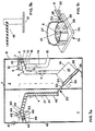
- the illustrated in Figure 1 first embodiment of an input and Exit control station for paid parking includes one Entry control station 1 and an exit control station 2, which in a common housing 3 or installed in adjacent housing are.
- the first embodiment therefore relates to a combined Entry and exit control station, reusable parking tickets 4 Spends and takes back.
- the parking tickets 4 are disc-shaped parking tickets from a substantially rigid or rigid material, in particular plastic.
- the Exterior shape of the park tickets 4 is selectable. However, round are preferred Parking tickets 4, as their ability to roll improves conveyability.
- the thickness of the parking tickets 4 or their edge design is chosen such that that the parking tickets have a circumferential running and contact area, which has a width of 2 to 8 mm.
- an identification element and optionally communication element fitted with a selectable identifier from the entry and exit control station can be read.
- the exit control station 2 comprises an exit-side take-back device 5, which includes a chute 6.
- the chute 6 is off a parking ticket input port 7 located in an exit side Housing wall 8 is located, and has such dimensions that the parking tickets 4 standing on its peripheral surface or rolling the chute 6th can slide down and can not fall over from this position.
- a bottom surface 9 of the chute 6 then forms for the park tickets 4 a tread.
- a reading and optionally provided communication device 11 At an initial portion 10 of the chute 6 is a reading and optionally provided communication device 11, by means of a inserted by an extending user through the input port 7 Parking ticket 4 is read and possibly described.
- the reading and optionally communication device 11 may in a known manner of a read head, optionally combined with a write head formed become.
- the reading and optionally communication device 11 is connected to a control device 12, the read values for Control of further connectable to the controller 11 devices processed.
- a lock 13 Downstream of the place where the reading and, where appropriate, communication device 11 is arranged, a lock 13 is provided, with the the chute 6 can be closed or released to the park tickets 4 for a selectable period of time within the range of the reading and optionally communication device 11 to hold.
- the direction the displaceability of the lock 13 is marked by a double arrow.
- the position of the lock 13 in the release position is dashed illustrated, the position of the lock 13 in the blocking position is shown by solid lines. For actuating the lock 13 this is connected to the control device 12.
- the return device 5 may further comprise a return chute 14, the downstream of the reading and optionally communication device 11 branches off from the chute 6 and to a return opening 15th in the exit-side housing wall 8 runs.
- a return chute 14 the downstream of the reading and optionally communication device 11 branches off from the chute 6 and to a return opening 15th in the exit-side housing wall 8 runs.
- Communication device 11 as not entitled to the exit Parktickets 4 can on this return chute 14 to a Users are returned.
- a rocker or a transverse pin 16 is provided, whose or Pivoting range in and out of the chute 6 marked by a double arrow is.
- the actuation of the rocker 16 is via the control device 12 triggered, for which purpose this is connected to the control device 12.
- control device 12 may have a roadway 17 crossing parking barrier 18 (see Fig. 1b) to be connected to their To open and close.
- the control device may further a cash register, not shown, be connected to this the exit authorization for a parking ticket 4, in particular marked through its identifier, to get signaled.
- the take-back device 5 is arranged downstream of at least one pushing device 19 associated with a parking ticket retrieval device 20, the the take-back device 5 with a drive-side output device 40 connects.
- the Parkticket Wegschreibschreibtechnische 20 includes in addition to the at least one pusher 19 a transport channel 21, with an inlet 22 to an output 23 of the thruster 19 and with an outlet 24 to the entrance side output device 21 connects. Characterized in that the chute 6 connects to the pusher 19 and with the park tickets 4 of the pusher returned by the users 19, this can be added to the park tickets 4 in the Promote transport channel 21, the park tickets to the entrance side Output device 40 passes.
- the pusher 19 is preferably formed by amaschineteller, as shown in Fig. 1c.
- the drive plate comprises a combined Parking ticket separator and driver 26 and an attached Reservoir 27 for receiving a plurality of parking tickets.
- the parking ticket singulator and driver 26 forms a bottom of the storage tank 27.
- the parking ticket separation and driver comprises a parking lot catching disk, which is from a Perforated disk 28 (see Fig. 4 and 5) is formed, which is rotatable about a Guideway 29 (see Fig. 6 and 7) stored and by means of a motor 30th can be driven continuously or stepwise.
- FIG. 1c As can be seen from Figures 1c, 4 and 5, has the perforated disc 28 a plurality of concentrically arranged holes 31. Since according to the described Embodiment round parking tickets 4 are used it is in the holes 31 to round recesses whose diameter slightly exceeds the diameter of the parking tickets 4, so slide the parking tickets 4 in the holes 31 and through them in the underlying guideway 29 may fall.
- the perforated disc 28 according to Fig. 1c differs from the perforated disc 28 shown in FIG. 4 only with respect to the number of holes 31. Otherwise, the perforated discs 28 built the same, so that with regard to the detailed description on the in the Figures 4 and 5 illustrated perforated disk 28 is referenced.
- the perforated disc 28 protruding back Guide webs 32, with which the perforated disc 28 in the Guideway 29 engages.
- the guide webs 32 surround each hole 31 mouth-like with a circumferential Mouth opening 33 through which a parking ticket 4 are discharged can.
- a park ticket 4 caught by a hole 31 is accordingly defeated the hole 31 through in the underlying guide rail 29 and is upon rotation of the perforated disc 28 in the direction of an output 23 of the mouth-like the respective hole 31 surrounding guide webs 32 in the area held the respective hole 31 and moved.
- the sense of rotation depends on the selectable direction of the output 23.
- the guideway 29 terminates in a Exit 23, which is formed by a bow exit and a straight line here Spout forms.
- This output 23 has lateral boundary edges 35, 36 for a positive guidance of the in the guideway 29th ongoing parking tickets in the exit 23. Due to the rotational movement of the Perforated disk 28 and the forced operation in the output 23 are in the Guided track running Parktickets 4 through the mouth opening 33 from the Perforated disk 28 moved out.
- the guideway 29 thus has a loop-like shape, with a Loop bow 37 arranged on the circular arc of the arrangement of the holes 31 and a dead end 38 at a selectable arcuate portion is provided, this dead end 38 is selected so that the sheet 37, the fishing route for the parking tickets 4 in the reservoir 27 represents and thus for the separation of the park tickets. 4 ensures as long as possible.
- the dead end 38 is adjacent to the exit 23.
- the holes 31 not only mouth-like, but also include edge-side, parallel to the peripheral surface between each two mouth openings 34 extending second guide ribs 39.
- These second Guide webs 39 form thrust and support surfaces for each one of the Perforated disk 28 in the exit 23 funded parking ticket. 4
- the parking tickets 4 are successively from the perforated disc 28 in the output 23 and from there in the Transport channel 21 moves.
- the second guide webs 39 cause a in the exit 23 moved parking ticket 4 at a further rotation of the Perforated disk 28 receives a thrust movement for forward movement and is also supported.
- a next Parking ticket 4 is moved into the exit, this exerts new in the exit 23 entering Park ticket 4 a push movement on the already in the Exit lying park tickets 4 and is even from the second guide webs 39 promoted through the exit.
- the pushing device 19 is a perforated disk 28, which is erected upright, as shown in Fig. 1a. This will catch the parking tickets 4 through the perforated disc 28 and thus simplifies their isolation. Furthermore, then the Output 23 are arranged on the head side of the pusher 19 and a Art form chute, which improves the structure of the push Association 41.
- the subsequent to the pusher 19 transport channel 21 closes with at least one riser 42 to the output 23 of the thruster 19, in which the pusher 41 moves forward.
- the climb reached height gradient is preferably chosen such that the outlet 24 of the transport channel the returned park tickets 4 passes to the output device 40 at a height level, that the parking tickets 4 via a provided in the output device 40 Chute 43 can be issued.
- This chute 43 ends in a driveway discharge opening 44 in the entrance side housing wall 45, wherein the discharge opening 44 and the return opening 7 in preferably the same user-friendly height.
- the cross section of the transport channel 21 is chosen so that this Parking tickets in an upright, rollable location leads, as in Fig. 1a is shown.
- the length guide of the Transortkanals 21 is selectable, whereby sections with different height gradient can be combined are. Furthermore, curve sections may be included.
- the output device 40 is similar to the back-5 device equipped with a reading and optionally communication device 46, by means of which is read from a user entering by pressing a call button 47 parking ticket 4 and possibly described.
- the reading and optionally communication device 46 can be formed in a known manner by a read head, optionally combined with a write head.
- the reading and optionally communication device 46 is connected to a control device 48, which processes the read values for controlling further devices connectable to the control device 48. Downstream of the location where the reading and, if appropriate, communication device 46 is arranged, a barrier 49 is provided with which the chute 43 can be closed or released in order to issue a parking ticket 4 only on demand.
- the direction of displaceability of the barrier 49 is marked by a double arrow.
- the position of the lock 49 in the release position is shown in dashed lines, the position of the lock 49 in the blocking position is shown by solid lines. To actuate the lock 49, this is connected to the control device 48.
- the control devices 12, 48 can be connected to a common control device be summarized. At least one control device 12, 48, preferably the controller 48 of the dispenser 40, is also the drive 30 for the actuation of the push device 19 is connected. As required and depending on a level in Output device 40, in particular in the chute 43, the Pusher 19 driven and new parking tickets from the return device 5 are returned to the output device 40. By doing Chute 43 of the output device 40 can to a level controller 50 may be provided, which is also connected to the control device 48 is. The return of the park tickets 4, their repatriation by Operation of the thruster 19 as well as the issue of the park tickets can be coordinated so that a continuous Passage of the park tickets 4 is achieved. The interposition of Buffer lines and / or storage containers, in particular the storage container 27 of the thruster 19, increases the flexibility of the system.
- the dispenser 40 may be preceded by a reservoir be promoted, in which the Parkticket Wegschreibvortechnisch 20 and from the the output device 40 picks up required parking tickets.
- the described entry and exit control station works as follows: A park customer who wants to drive out at the end of a parking operation throws be entitled to exit parking ticket 4 in the exit input opening 7, whereby it enters the chute 6 of the take-back device 5. At the reading and optionally communication device is the parking ticket 4 read, in particular its identifier. Lies for this Identification of the control device 12 before an exit authorization, so will the parking barrier 18 is opened and the park ticket withdrawn falls over the chute 6 in the pusher, and first in the attached storage tank 27 to which the chute 6 ends.
- FIGS. 2a to 2c show a second embodiment of the invention Exit control station, differing from the previously described characterized in that the entrance control station 1 spatially can be placed separately from the exit control station 2.
- the Parkticket Wegschreibschreibtechnisch 20 with pushing device 19 and transport channel 21 is then preferably installed in the entrance control station 1.
- the connection between the return device 5 and the pushing device 19 takes place with the interposition of a connection channel 51, the spatial distances between the entrance and exit control station can bridge.
- the connecting channel 51 runs with a Gradient from one to the other station 1, 2, so that alone below Gravity effect the parking tickets 4 through the connecting channel 51 movable are.
- the connecting channel 51 preferably has a same cross section as the chute 6 of the return device 5, to which he with a Start connects.
- the end of the connecting channel 51 connects to the Pusher 19 on. Otherwise, the comments on the figures apply 1a to 1c.
- the parking barrier 18 according to FIG. 1b and the pushing device 19 according to FIG. 1c correspond to those of FIGS. 2b and 2c.
- FIGS. 3a to 3c show a third embodiment of the invention Exit control station 1, 2, which differs from the first embodiment according to the figures 1a to 1c differs in that the entrance control station 1 spatially separated from the exit control station is and as in the second embodiment, an additional den Spatial distance bridging connection means is provided.
- the entrance control station 1 and the exit control station 2 each with a Parkticket Wegtechnischvorraum 20, 20 "from pushing device 19, 19" and Transport channel 21, 21 “equipped, wherein the transport channel 21" of Exit control station directly to the pushing device 19 of the entrance control station or with the interposition of an additional connection channel 51 ".
- FIGS. 1a to 1c apply corresponding to the third embodiment according to the figures 3a to 3c.
- the marked with a double line at the reference numerals Components are the same as those with the same reference numerals without double line educated.
Landscapes
- Physics & Mathematics (AREA)
- General Physics & Mathematics (AREA)
- Business, Economics & Management (AREA)
- Finance (AREA)
- Devices For Checking Fares Or Tickets At Control Points (AREA)
Claims (21)
- Station de contrôle d'entrée et se sortie pour places de stationnement payantes comprenant du côté de l'entrée un dispositif de distribution (40) de tickets de parcage (4) en forme de disques présentant un signe distinctif et du côté de la sortie un dispositif de reprise (5) de ces tickets, la station de contrôle comprenant un dispositif de lecture (46, 11 ) associé respectivement aux dispositifs de distribution et de reprise (40, 5), ainsi qu'au moins un dispositif de commande (12, 48) pour une distribution et une reprise des tickets de parcage (4) de l'utilisateur, caractérisée en ce que les dispositifs de distribution et de reprise (40, 5) sont couplés l'un à l'autre par le biais d'un dispositif de retour (20) des tickets de parcage, ce dispositif de retour comprenant un canal de transport (21) qui guide les tickets de parcage (4) et qui se raccorde au dispositif distributeur (40) par le biais d'une sortie (24), et au moins un dispositif de poussée (19) agencé à la suite du dispositif de reprise (5), le canal de transport (21) se raccordant à une sortie (23) du dispositif de poussée (19) par le biais d'au moins une section ascendante (42) pour la réception d'un lot (41) de tickets de parcage (4) empilés sous l'effet de la pesanteur et contre lequel les tickets de parcage (4) qui sont reçus par l'installation de poussée (19) et qui exercent un mouvement de poussée sur l'élément de la file respectivement le plus bas peuvent être acheminés à travers le canal de transport (21) dans et par un courant de masse des tickets de parcage, et en ce que le dispositif de commande (48) commande le fonctionnement de l'installation de poussée (19, 19") en fonction de la distribution ou de la reprise d'un ticket de parcage (4).
- Station de contrôle d'entrée et de sortie selon la revendication 1, caractérisée en ce que le dispositif de retour (20) des tickets de parcage est intégré dans une station de contrôle d'entrée et de sortie combinée (1, 2).
- Station de contrôle d'entrée et de sortie selon la revendication 1, caractérisée en ce que la station de contrôle d'entrée (1) est un module indépendant dans lequel sont intégrés le canal de transport (21) et l'installation de poussée (19), l'installation de poussée (19) étant raccordée au dispositif de reprise (5) par le biais d'un canal de liaison (51) qui enjambe un intervalle spatial entre la station de contrôle d'entrée (1) et le station de contrôle de sortie (2).
- Station de contrôle d'entrée et de sortie selon la revendication 3, caractérisée en ce que le canal de liaison (51) est conduit jusqu'à l'installation de poussée (19) avec une pente.
- Station de contrôle d'entrée et de sortie selon la revendication 1, caractérisée en ce que la station de contrôle de sortie (2) est un module indépendant dans lequel l'installation de poussée (19) est intégrée, le canal de transport (21) étant réalisé, du côté de son extrémité terminale, à la façon d'un canal de liaison (51) qui enjambe un intervalle spatial entre la station de contrôle d'entrée (1) et la station de contrôle de sortie (2).
- Station de contrôle d'entrée et de sortie selon la revendication 5, caractérisée en ce que le canal de liaison (51) se raccorde au dispositif de distribution (40) par l'intermédiaire d'une section de canal de liaison présentant une pente.
- Station de contrôle d'entrée et de sortie selon la revendication 1, caractérisée en ce que la station de contrôle d'entrée (1) et la station de contrôle de sortie (2) sont des modules séparés distants spatialement dans chacun desquels est intégré un canal de transport (21, 21") et une installation de poussée (13, 13") de façon que la sortie du canal de transport (21") de la station de contrôle de sortie (2) ou d'un canal de liaison (51) se raccorde à une entrée de l'installation de poussée (19").
- Station de contrôle d'entrée et sortie selon l'une des revendications 1 à 7, caractérisée en ce que le dispositif de distribution (40) est agencé avant un accumulateur ou une trémie dans lequel ou au niveau duquel se termine le canal de transport (21).
- Station de contrôle d'entrée et de sortie selon l'une des revendications 1 à 8, caractérisée en ce que le dispositif de reprise (5) comprend au moins du côté de la sortie une trémie (6) pour les tickets de parcage (4) par l'intermédiaire de laquelle le dispositif de reprise (5) se raccorde à l'installation de poussée (19).
- Station de contrôle d'entrée et de sortie selon l'une des revendications 1 à 9, caractérisée en ce que les dimensions du canal de transport (21) sont telles qu'elles permettent d'éviter que les tickets de parcage (4) ne basculent depuis une position droite dans laquelle ils sont susceptibles de rouler lors de leur déplacement à travers le canal de transport (21).
- Station de contrôle d'entrée et de sortie selon l'une des revendications 1 à 10, caractérisée en ce que le dispositif de distribution (40) et le dispositif de reprise (5) comprennent chacun une trémie de distribution, respectivement de reprise (43, 6) par l'intermédiaire desquelles les tickets de parcage (4) peuvent être déplacés selon leur surface périphérique pour une distribution ou une introduction roulante.
- Station de contrôle d'entrée et de sortie selon la revendication 11, caractérisée en ce qu'elle comprend le long des trémies de distribution et de reprise (43, 6) un dispositif de lecture (46, 11 ) et le cas échéant un dispositif de communication pour une lecture et le cas échéant une écriture des tickets de parcage (4) à distribuer ou à reprendre.
- Station de contrôle d'entrée et de sortie selon la revendication 12, caractérisée en ce que la trémie de distribution et de reprise (43, 6) comprend un dispositif de fermeture (49, 13) obturant un passage de trémie pour retenir momentanément les tickets de parcage (4) au voisinage du dispositif de lecture (46, 11).
- Station de contrôle d'entrée et de sortie selon l'une des revendications 1 à 13, caractérisée en ce que le dispositif de lecture (46, 11) est relié à une commande pour l'actionnement d'une barrière de parking (4).
- Station de contrôle selon l'une des revendications 1 à 14, caractérisée en ce que l'installation de poussée (19, 19") est agencée sous la forme d'un plateau moteur avec un accumulateur (27, 27") disposé dessus.
- Station de contrôle d'entrée et se sortie selon la revendication 15, caractérisée en ce que le plateau moteur comprend une installation de séparation (26) des tickets de parcage qui achemine à chaque fois de manière répétitive un ticket de parcage (4) dans le canal de transport (21).
- Station de contrôle d'entrée et de sortie selon la revendication 15 ou 16, caractérisée en ce que le plateau moteur comprend un disque rotatif de saisie et d'entraínement d'un ticket de parcage qui achemine les tickets de parcage (4) séparés le long d'une glissière de guidage (29) incurvée qui se termine par une section de sortie (23) dans le canal de transport (21).
- Station de contrôle d'entrée et de sortie selon la revendication 17, caractérisée en ce que le disque de prise et d'entraínement d'un ticket de parcage se présente sans la forme d'un disque à trous (28) avec une pluralité de trous (31) disposés concentriquement, le diamètre des trous excédant faiblement le diamètre des tickets de parcage (4), et le disque à trous (28) présentant sur sa face arrière tournée du côté de la glissière de guidage (29) des rebords de guidage (33) faisant saillie autour de chaque trou (31) à la façon de bouches avec une embouchure périphérique (34) pour la distribution d'un ticket de parcage (4), et des rebords de guidage (39) étant prévues entre deux embouchure (34) qui, lorsque le disque à trous (28) tourne, poussent dans la trémie de transport (21) ceux des tickets de parcage (4) qui sont tombés dans la glissière de guidage (24) à travers un des trous (31), qui sont guidés le long de celui-ci au moyen du disque à trous (28) et qui peuvent être déchargés à travers l'embouche (34).
- Station de contrôle d'entrée et de sortie selon la revendication 18, caractérisée en ce que les rebords de guidage (33) en forme de bouche possèdent une profondeur qui fait saillie au moins partiellement dans la glissière de guidage (29) et qui correspond au moins à l'épaisseur des tickets de parcage (4), de sorte que les tickets de parcage (4) qui sont tombés à travers un trou (34) peuvent être guidés et poussés sous le disque à trous (28) dans la section de sortie (23) par les rebords de guidage (33) en forme de bouche.
- Station de contrôle d'entrée et de sortie selon l'une des revendications 16 à 19, caractérisée en ce que l'installation de séparation et d'entraínement (26) est mise en place de manière verticale et en pente et se raccorde à la tête du canal de transport (21).
- Station de contrôle d'entrée et de sortie selon l'une des revendications 1 à 20, caractérisée en ce que le dispositif de commande (12, 48) enclenche et déclenche pas à pas un moteur (30, 30") pour l'actionnement de l'installation de poussée (19, 19") pour délivrer à chaque fois un ticket de parcage (4).
Applications Claiming Priority (3)
| Application Number | Priority Date | Filing Date | Title |
|---|---|---|---|
| DE19638286 | 1996-09-19 | ||
| DE19638286A DE19638286C2 (de) | 1996-09-19 | 1996-09-19 | Ein- und Ausfahrtkontrollstation für kostenpflichtige Parkplätze |
| US08/787,988 US5913400A (en) | 1996-09-19 | 1997-01-23 | Entrance-control and departure-control station for charge-related car park |
Publications (3)
| Publication Number | Publication Date |
|---|---|
| EP0831427A2 EP0831427A2 (fr) | 1998-03-25 |
| EP0831427A3 EP0831427A3 (fr) | 2000-02-02 |
| EP0831427B1 true EP0831427B1 (fr) | 2005-05-18 |
Family
ID=26029554
Family Applications (1)
| Application Number | Title | Priority Date | Filing Date |
|---|---|---|---|
| EP97116135A Expired - Lifetime EP0831427B1 (fr) | 1996-09-19 | 1997-09-17 | Station de contrôle d'entrée et de sortie pour des emplacements de stationnement payants |
Country Status (5)
| Country | Link |
|---|---|
| US (1) | US5913400A (fr) |
| EP (1) | EP0831427B1 (fr) |
| AT (1) | ATE295979T1 (fr) |
| DE (2) | DE19638286C2 (fr) |
| ES (1) | ES2244985T3 (fr) |
Families Citing this family (6)
| Publication number | Priority date | Publication date | Assignee | Title |
|---|---|---|---|---|
| JP2002117428A (ja) * | 2000-10-06 | 2002-04-19 | Asahi Seiko Kk | コインホッパ |
| DE10160276A1 (de) | 2001-12-07 | 2003-06-26 | Siemens Ag | Antriebsanordnung für wenigstens ein in einem Fahrtschreiber angeordnetes Chipkarten-Aufnahmeaggregat zum Verbringen einer Chipkarte in die Entnahmeposition |
| DE10306525A1 (de) * | 2003-02-14 | 2004-09-02 | Be-Barmatic Parksysteme Gmbh | Multifunktionale Einnahme- und Ausgabevorrichtung für scheibenförmige Datenträger, insbesondere Transpondermünzen |
| FR2858869B1 (fr) * | 2003-08-13 | 2006-01-13 | All Watt Elec | Procede de gestion d'un lieu a peage en entree et en sortie tel qu'un parking et dispositif associe |
| TWI483217B (zh) * | 2013-02-01 | 2015-05-01 | Nat Univ Chin Yi Technology | Intelligent image monitoring vehicle service station system |
| US10839651B2 (en) * | 2016-11-11 | 2020-11-17 | Smart Industries Corporation | Arcade game with RFID reader |
Family Cites Families (8)
| Publication number | Priority date | Publication date | Assignee | Title |
|---|---|---|---|---|
| FR2266229A1 (en) * | 1974-03-26 | 1975-10-24 | Distribution Automatique Cie F | Coin-operated vending machine for boxed articles - has vertical columns containing pile of articles dispensed from top |
| US4319674A (en) * | 1975-12-10 | 1982-03-16 | Electron, Inc. | Automated token system |
| JPS55166288U (fr) * | 1979-05-17 | 1980-11-29 | ||
| WO1990002389A1 (fr) * | 1988-08-18 | 1990-03-08 | Popham, Charles, F. | Appareil de stockage et de distribution de pieces |
| DE9302481U1 (de) * | 1993-02-20 | 1993-04-08 | Parkautomatik Hans Farmont GmbH, 4000 Düsseldorf | Parkkarte zur gebührenpflichtigen Betätigung einer Parkschranke |
| US5500515A (en) * | 1993-06-29 | 1996-03-19 | Farmont; Johann | Method of using a parking card for operating a parking barrier for pay parking |
| DE9407260U1 (de) * | 1993-09-10 | 1994-06-23 | Farmont Technik GmbH & Co KG, 40217 Düsseldorf | Ausgabevorrichtung für scheibenförmige Parktickets |
| JP3439556B2 (ja) * | 1994-12-28 | 2003-08-25 | 日本信号株式会社 | カード状記録媒体処理装置 |
-
1996
- 1996-09-19 DE DE19638286A patent/DE19638286C2/de not_active Expired - Fee Related
-
1997
- 1997-01-23 US US08/787,988 patent/US5913400A/en not_active Expired - Lifetime
- 1997-09-17 ES ES97116135T patent/ES2244985T3/es not_active Expired - Lifetime
- 1997-09-17 EP EP97116135A patent/EP0831427B1/fr not_active Expired - Lifetime
- 1997-09-17 AT AT97116135T patent/ATE295979T1/de active
- 1997-09-17 DE DE59712314T patent/DE59712314D1/de not_active Expired - Lifetime
Also Published As
| Publication number | Publication date |
|---|---|
| ES2244985T3 (es) | 2005-12-16 |
| US5913400A (en) | 1999-06-22 |
| DE19638286C2 (de) | 1998-07-02 |
| DE19638286A1 (de) | 1998-04-02 |
| EP0831427A2 (fr) | 1998-03-25 |
| ATE295979T1 (de) | 2005-06-15 |
| EP0831427A3 (fr) | 2000-02-02 |
| DE59712314D1 (de) | 2005-06-23 |
Similar Documents
| Publication | Publication Date | Title |
|---|---|---|
| DE2437994C3 (de) | Gerät zum Deponieren von Einlagen, wie Geldscheinen, Schecks o.dgl | |
| DE3324731C2 (fr) | ||
| DE4400744A1 (de) | Ein- und Ausgabevorrichtung für runde, ein Identifikations- und/oder Kommunikationselement aufweisende Parkkarten zur gebührenpflichtigen Betätigung einer Parkschranke | |
| DE68913609T2 (de) | Münzenverarbeitungsvorrichtung. | |
| DE69504729T2 (de) | Vorrichtung zur Bevorratung von Zigarettenpackungen in einer Warenabrechnungsablage | |
| DE69602310T2 (de) | Vorrichtung zum Stapeln und Sammeln von Geldscheinen mit Rückgabemöglichkeit | |
| DE3312225A1 (de) | Vorrichtung zur zuruecknahme von an der ausgabestation eines automatischen bankschalters vorgelegten, aber nicht entnommenen papierbanknoten | |
| DE19638286C2 (de) | Ein- und Ausfahrtkontrollstation für kostenpflichtige Parkplätze | |
| DE69903788T2 (de) | Münzausgabevorrichtung für münzbetätigte automaten | |
| DE2758910C3 (de) | Münztransportvorrichtung für Spielautomaten | |
| DE69900962T2 (de) | Gerät zum Ausgeben von Geldscheinen | |
| DE3739159C2 (fr) | ||
| EP0831426B1 (fr) | Distributeur pour tickets de parking en forme de disque | |
| EP0669270A1 (fr) | Dispositif pour détecter l'accès payant à un espace collecteur à ordures | |
| DE2556865B2 (de) | Vorrichtung zur annahme, speicherung und rueckgabe von muenzen bei verkaufsautomaten, insbesondere fahrkartenautomaten | |
| DE3787888T2 (de) | Vorrichtung zum Wechseln von Münzen. | |
| EP0821325A1 (fr) | Dispositif de stockage autoremplissable pour des porteurs de données en forme de carte | |
| DE20016022U1 (de) | Kartenautomat für Zugangsberechtigungssysteme | |
| DE4414303C2 (de) | Ausgabevorrichtung für scheibenförmige Parktickets | |
| DE19705700C2 (de) | Vorrichtung zur Rücknahme von becher- oder dosenförmigen Behältnissen | |
| EP0637395B1 (fr) | Dispositif d'introduction et d'emission pour cartes de stationnement rondes contenant un element d'identification et/ou de communication pour l'actionnement payant d'une barriere de parc de stationnement | |
| DE3304549A1 (de) | Selbstfuellende restgeldeinheit | |
| DE2423688A1 (de) | Rueckgeldgeber | |
| DE2345177A1 (de) | Verkaufsautomat, insbesondere fuer grosspackungen wie flaschenkaesten | |
| AT402394B (de) | Automatische anlage zum kommissionieren von stückgütern |
Legal Events
| Date | Code | Title | Description |
|---|---|---|---|
| PUAI | Public reference made under article 153(3) epc to a published international application that has entered the european phase |
Free format text: ORIGINAL CODE: 0009012 |
|
| AK | Designated contracting states |
Kind code of ref document: A2 Designated state(s): AT BE CH DE DK ES FI FR GB GR IE IT LI LU MC NL PT SE |
|
| PUAL | Search report despatched |
Free format text: ORIGINAL CODE: 0009013 |
|
| AK | Designated contracting states |
Kind code of ref document: A3 Designated state(s): AT BE CH DE DK ES FI FR GB GR IE IT LI LU MC NL PT SE |
|
| 17P | Request for examination filed |
Effective date: 20000404 |
|
| AKX | Designation fees paid |
Free format text: AT BE CH DE DK ES FR GB GR IE IT LI LU MC NL PT SE |
|
| RBV | Designated contracting states (corrected) |
Designated state(s): AT BE CH DE DK ES FI FR GB GR IE IT LI LU MC NL PT SE |
|
| 17Q | First examination report despatched |
Effective date: 20010905 |
|
| GRAP | Despatch of communication of intention to grant a patent |
Free format text: ORIGINAL CODE: EPIDOSNIGR1 |
|
| GRAS | Grant fee paid |
Free format text: ORIGINAL CODE: EPIDOSNIGR3 |
|
| GRAA | (expected) grant |
Free format text: ORIGINAL CODE: 0009210 |
|
| AK | Designated contracting states |
Kind code of ref document: B1 Designated state(s): AT BE CH DE DK ES FI FR GB GR IE IT LI LU MC NL PT SE |
|
| PG25 | Lapsed in a contracting state [announced via postgrant information from national office to epo] |
Ref country code: NL Free format text: LAPSE BECAUSE OF FAILURE TO SUBMIT A TRANSLATION OF THE DESCRIPTION OR TO PAY THE FEE WITHIN THE PRESCRIBED TIME-LIMIT Effective date: 20050518 Ref country code: IT Free format text: LAPSE BECAUSE OF FAILURE TO SUBMIT A TRANSLATION OF THE DESCRIPTION OR TO PAY THE FEE WITHIN THE PRESCRIBED TIME-LIMIT;WARNING: LAPSES OF ITALIAN PATENTS WITH EFFECTIVE DATE BEFORE 2007 MAY HAVE OCCURRED AT ANY TIME BEFORE 2007. THE CORRECT EFFECTIVE DATE MAY BE DIFFERENT FROM THE ONE RECORDED. Effective date: 20050518 Ref country code: IE Free format text: LAPSE BECAUSE OF FAILURE TO SUBMIT A TRANSLATION OF THE DESCRIPTION OR TO PAY THE FEE WITHIN THE PRESCRIBED TIME-LIMIT Effective date: 20050518 Ref country code: FI Free format text: LAPSE BECAUSE OF FAILURE TO SUBMIT A TRANSLATION OF THE DESCRIPTION OR TO PAY THE FEE WITHIN THE PRESCRIBED TIME-LIMIT Effective date: 20050518 |
|
| REG | Reference to a national code |
Ref country code: GB Ref legal event code: FG4D Free format text: NOT ENGLISH |
|
| REG | Reference to a national code |
Ref country code: CH Ref legal event code: EP |
|
| REG | Reference to a national code |
Ref country code: IE Ref legal event code: FG4D Free format text: LANGUAGE OF EP DOCUMENT: GERMAN |
|
| REF | Corresponds to: |
Ref document number: 59712314 Country of ref document: DE Date of ref document: 20050623 Kind code of ref document: P |
|
| PG25 | Lapsed in a contracting state [announced via postgrant information from national office to epo] |
Ref country code: SE Free format text: LAPSE BECAUSE OF FAILURE TO SUBMIT A TRANSLATION OF THE DESCRIPTION OR TO PAY THE FEE WITHIN THE PRESCRIBED TIME-LIMIT Effective date: 20050818 Ref country code: GR Free format text: LAPSE BECAUSE OF FAILURE TO SUBMIT A TRANSLATION OF THE DESCRIPTION OR TO PAY THE FEE WITHIN THE PRESCRIBED TIME-LIMIT Effective date: 20050818 Ref country code: DK Free format text: LAPSE BECAUSE OF FAILURE TO SUBMIT A TRANSLATION OF THE DESCRIPTION OR TO PAY THE FEE WITHIN THE PRESCRIBED TIME-LIMIT Effective date: 20050818 |
|
| PG25 | Lapsed in a contracting state [announced via postgrant information from national office to epo] |
Ref country code: MC Free format text: LAPSE BECAUSE OF NON-PAYMENT OF DUE FEES Effective date: 20050930 Ref country code: LU Free format text: LAPSE BECAUSE OF NON-PAYMENT OF DUE FEES Effective date: 20050930 Ref country code: LI Free format text: LAPSE BECAUSE OF NON-PAYMENT OF DUE FEES Effective date: 20050930 Ref country code: CH Free format text: LAPSE BECAUSE OF NON-PAYMENT OF DUE FEES Effective date: 20050930 Ref country code: BE Free format text: LAPSE BECAUSE OF NON-PAYMENT OF DUE FEES Effective date: 20050930 |
|
| GBT | Gb: translation of ep patent filed (gb section 77(6)(a)/1977) |
Effective date: 20050913 |
|
| PG25 | Lapsed in a contracting state [announced via postgrant information from national office to epo] |
Ref country code: PT Free format text: LAPSE BECAUSE OF FAILURE TO SUBMIT A TRANSLATION OF THE DESCRIPTION OR TO PAY THE FEE WITHIN THE PRESCRIBED TIME-LIMIT Effective date: 20051018 |
|
| NLV1 | Nl: lapsed or annulled due to failure to fulfill the requirements of art. 29p and 29m of the patents act | ||
| REG | Reference to a national code |
Ref country code: ES Ref legal event code: FG2A Ref document number: 2244985 Country of ref document: ES Kind code of ref document: T3 |
|
| REG | Reference to a national code |
Ref country code: IE Ref legal event code: FD4D |
|
| PLBE | No opposition filed within time limit |
Free format text: ORIGINAL CODE: 0009261 |
|
| STAA | Information on the status of an ep patent application or granted ep patent |
Free format text: STATUS: NO OPPOSITION FILED WITHIN TIME LIMIT |
|
| ET | Fr: translation filed | ||
| 26N | No opposition filed |
Effective date: 20060221 |
|
| REG | Reference to a national code |
Ref country code: CH Ref legal event code: PL |
|
| BERE | Be: lapsed |
Owner name: FARMONT TECHNIK G.M.B.H. & CO. KG Effective date: 20050930 |
|
| PGFP | Annual fee paid to national office [announced via postgrant information from national office to epo] |
Ref country code: ES Payment date: 20100924 Year of fee payment: 14 |
|
| PGFP | Annual fee paid to national office [announced via postgrant information from national office to epo] |
Ref country code: FR Payment date: 20101005 Year of fee payment: 14 Ref country code: AT Payment date: 20100914 Year of fee payment: 14 |
|
| PGFP | Annual fee paid to national office [announced via postgrant information from national office to epo] |
Ref country code: GB Payment date: 20100921 Year of fee payment: 14 |
|
| PGFP | Annual fee paid to national office [announced via postgrant information from national office to epo] |
Ref country code: DE Payment date: 20101125 Year of fee payment: 14 |
|
| GBPC | Gb: european patent ceased through non-payment of renewal fee |
Effective date: 20110917 |
|
| REG | Reference to a national code |
Ref country code: FR Ref legal event code: ST Effective date: 20120531 |
|
| REG | Reference to a national code |
Ref country code: DE Ref legal event code: R119 Ref document number: 59712314 Country of ref document: DE Effective date: 20120403 |
|
| PG25 | Lapsed in a contracting state [announced via postgrant information from national office to epo] |
Ref country code: DE Free format text: LAPSE BECAUSE OF NON-PAYMENT OF DUE FEES Effective date: 20120403 |
|
| PG25 | Lapsed in a contracting state [announced via postgrant information from national office to epo] |
Ref country code: FR Free format text: LAPSE BECAUSE OF NON-PAYMENT OF DUE FEES Effective date: 20110930 Ref country code: GB Free format text: LAPSE BECAUSE OF NON-PAYMENT OF DUE FEES Effective date: 20110917 |
|
| REG | Reference to a national code |
Ref country code: AT Ref legal event code: MM01 Ref document number: 295979 Country of ref document: AT Kind code of ref document: T Effective date: 20110917 |
|
| PG25 | Lapsed in a contracting state [announced via postgrant information from national office to epo] |
Ref country code: AT Free format text: LAPSE BECAUSE OF NON-PAYMENT OF DUE FEES Effective date: 20110917 |
|
| REG | Reference to a national code |
Ref country code: ES Ref legal event code: FD2A Effective date: 20130531 |
|
| PG25 | Lapsed in a contracting state [announced via postgrant information from national office to epo] |
Ref country code: ES Free format text: LAPSE BECAUSE OF NON-PAYMENT OF DUE FEES Effective date: 20110918 |