EP0833062B1 - Dispositif d'entrainement pour moteur hydraulique - Google Patents
Dispositif d'entrainement pour moteur hydraulique Download PDFInfo
- Publication number
- EP0833062B1 EP0833062B1 EP96906933A EP96906933A EP0833062B1 EP 0833062 B1 EP0833062 B1 EP 0833062B1 EP 96906933 A EP96906933 A EP 96906933A EP 96906933 A EP96906933 A EP 96906933A EP 0833062 B1 EP0833062 B1 EP 0833062B1
- Authority
- EP
- European Patent Office
- Prior art keywords
- port
- pressure
- valve
- hydraulic motor
- tank
- Prior art date
- Legal status (The legal status is an assumption and is not a legal conclusion. Google has not performed a legal analysis and makes no representation as to the accuracy of the status listed.)
- Expired - Lifetime
Links
- 230000007935 neutral effect Effects 0.000 claims abstract description 67
- 239000012530 fluid Substances 0.000 claims description 144
- 238000010276 construction Methods 0.000 description 6
- 238000010586 diagram Methods 0.000 description 5
- 230000000903 blocking effect Effects 0.000 description 4
- 238000006073 displacement reaction Methods 0.000 description 4
- 238000009434 installation Methods 0.000 description 3
- 238000005086 pumping Methods 0.000 description 3
- 230000035939 shock Effects 0.000 description 2
Images



Classifications
-
- E—FIXED CONSTRUCTIONS
- E02—HYDRAULIC ENGINEERING; FOUNDATIONS; SOIL SHIFTING
- E02F—DREDGING; SOIL-SHIFTING
- E02F9/00—Component parts of dredgers or soil-shifting machines, not restricted to one of the kinds covered by groups E02F3/00 - E02F7/00
- E02F9/08—Superstructures; Supports for superstructures
- E02F9/10—Supports for movable superstructures mounted on travelling or walking gears or on other superstructures
- E02F9/12—Slewing or traversing gears
- E02F9/121—Turntables, i.e. structure rotatable about 360°
- E02F9/128—Braking systems
-
- F—MECHANICAL ENGINEERING; LIGHTING; HEATING; WEAPONS; BLASTING
- F15—FLUID-PRESSURE ACTUATORS; HYDRAULICS OR PNEUMATICS IN GENERAL
- F15B—SYSTEMS ACTING BY MEANS OF FLUIDS IN GENERAL; FLUID-PRESSURE ACTUATORS, e.g. SERVOMOTORS; DETAILS OF FLUID-PRESSURE SYSTEMS, NOT OTHERWISE PROVIDED FOR
- F15B11/00—Servomotor systems without provision for follow-up action; Circuits therefor
- F15B11/08—Servomotor systems without provision for follow-up action; Circuits therefor with only one servomotor
-
- E—FIXED CONSTRUCTIONS
- E02—HYDRAULIC ENGINEERING; FOUNDATIONS; SOIL SHIFTING
- E02F—DREDGING; SOIL-SHIFTING
- E02F9/00—Component parts of dredgers or soil-shifting machines, not restricted to one of the kinds covered by groups E02F3/00 - E02F7/00
- E02F9/08—Superstructures; Supports for superstructures
- E02F9/10—Supports for movable superstructures mounted on travelling or walking gears or on other superstructures
- E02F9/12—Slewing or traversing gears
- E02F9/121—Turntables, i.e. structure rotatable about 360°
- E02F9/123—Drives or control devices specially adapted therefor
-
- E—FIXED CONSTRUCTIONS
- E02—HYDRAULIC ENGINEERING; FOUNDATIONS; SOIL SHIFTING
- E02F—DREDGING; SOIL-SHIFTING
- E02F9/00—Component parts of dredgers or soil-shifting machines, not restricted to one of the kinds covered by groups E02F3/00 - E02F7/00
- E02F9/20—Drives; Control devices
- E02F9/22—Hydraulic or pneumatic drives
- E02F9/2278—Hydraulic circuits
- E02F9/2285—Pilot-operated systems
-
- F—MECHANICAL ENGINEERING; LIGHTING; HEATING; WEAPONS; BLASTING
- F15—FLUID-PRESSURE ACTUATORS; HYDRAULICS OR PNEUMATICS IN GENERAL
- F15B—SYSTEMS ACTING BY MEANS OF FLUIDS IN GENERAL; FLUID-PRESSURE ACTUATORS, e.g. SERVOMOTORS; DETAILS OF FLUID-PRESSURE SYSTEMS, NOT OTHERWISE PROVIDED FOR
- F15B11/00—Servomotor systems without provision for follow-up action; Circuits therefor
- F15B11/02—Systems essentially incorporating special features for controlling the speed or actuating force of an output member
- F15B11/04—Systems essentially incorporating special features for controlling the speed or actuating force of an output member for controlling the speed
- F15B11/044—Systems essentially incorporating special features for controlling the speed or actuating force of an output member for controlling the speed by means in the return line, i.e. "meter out"
- F15B11/0445—Systems essentially incorporating special features for controlling the speed or actuating force of an output member for controlling the speed by means in the return line, i.e. "meter out" with counterbalance valves, e.g. to prevent overrunning or for braking
-
- F—MECHANICAL ENGINEERING; LIGHTING; HEATING; WEAPONS; BLASTING
- F15—FLUID-PRESSURE ACTUATORS; HYDRAULICS OR PNEUMATICS IN GENERAL
- F15B—SYSTEMS ACTING BY MEANS OF FLUIDS IN GENERAL; FLUID-PRESSURE ACTUATORS, e.g. SERVOMOTORS; DETAILS OF FLUID-PRESSURE SYSTEMS, NOT OTHERWISE PROVIDED FOR
- F15B11/00—Servomotor systems without provision for follow-up action; Circuits therefor
- F15B11/02—Systems essentially incorporating special features for controlling the speed or actuating force of an output member
- F15B11/04—Systems essentially incorporating special features for controlling the speed or actuating force of an output member for controlling the speed
- F15B11/05—Systems essentially incorporating special features for controlling the speed or actuating force of an output member for controlling the speed specially adapted to maintain constant speed, e.g. pressure-compensated, load-responsive
-
- F—MECHANICAL ENGINEERING; LIGHTING; HEATING; WEAPONS; BLASTING
- F15—FLUID-PRESSURE ACTUATORS; HYDRAULICS OR PNEUMATICS IN GENERAL
- F15B—SYSTEMS ACTING BY MEANS OF FLUIDS IN GENERAL; FLUID-PRESSURE ACTUATORS, e.g. SERVOMOTORS; DETAILS OF FLUID-PRESSURE SYSTEMS, NOT OTHERWISE PROVIDED FOR
- F15B13/00—Details of servomotor systems ; Valves for servomotor systems
- F15B13/02—Fluid distribution or supply devices characterised by their adaptation to the control of servomotors
- F15B13/04—Fluid distribution or supply devices characterised by their adaptation to the control of servomotors for use with a single servomotor
- F15B13/0401—Valve members; Fluid interconnections therefor
- F15B13/0402—Valve members; Fluid interconnections therefor for linearly sliding valves, e.g. spool valves
-
- F—MECHANICAL ENGINEERING; LIGHTING; HEATING; WEAPONS; BLASTING
- F15—FLUID-PRESSURE ACTUATORS; HYDRAULICS OR PNEUMATICS IN GENERAL
- F15B—SYSTEMS ACTING BY MEANS OF FLUIDS IN GENERAL; FLUID-PRESSURE ACTUATORS, e.g. SERVOMOTORS; DETAILS OF FLUID-PRESSURE SYSTEMS, NOT OTHERWISE PROVIDED FOR
- F15B2211/00—Circuits for servomotor systems
- F15B2211/30—Directional control
- F15B2211/305—Directional control characterised by the type of valves
- F15B2211/30505—Non-return valves, i.e. check valves
-
- F—MECHANICAL ENGINEERING; LIGHTING; HEATING; WEAPONS; BLASTING
- F15—FLUID-PRESSURE ACTUATORS; HYDRAULICS OR PNEUMATICS IN GENERAL
- F15B—SYSTEMS ACTING BY MEANS OF FLUIDS IN GENERAL; FLUID-PRESSURE ACTUATORS, e.g. SERVOMOTORS; DETAILS OF FLUID-PRESSURE SYSTEMS, NOT OTHERWISE PROVIDED FOR
- F15B2211/00—Circuits for servomotor systems
- F15B2211/40—Flow control
- F15B2211/405—Flow control characterised by the type of flow control means or valve
- F15B2211/40515—Flow control characterised by the type of flow control means or valve with variable throttles or orifices
-
- F—MECHANICAL ENGINEERING; LIGHTING; HEATING; WEAPONS; BLASTING
- F15—FLUID-PRESSURE ACTUATORS; HYDRAULICS OR PNEUMATICS IN GENERAL
- F15B—SYSTEMS ACTING BY MEANS OF FLUIDS IN GENERAL; FLUID-PRESSURE ACTUATORS, e.g. SERVOMOTORS; DETAILS OF FLUID-PRESSURE SYSTEMS, NOT OTHERWISE PROVIDED FOR
- F15B2211/00—Circuits for servomotor systems
- F15B2211/40—Flow control
- F15B2211/46—Control of flow in the return line, i.e. meter-out control
-
- F—MECHANICAL ENGINEERING; LIGHTING; HEATING; WEAPONS; BLASTING
- F15—FLUID-PRESSURE ACTUATORS; HYDRAULICS OR PNEUMATICS IN GENERAL
- F15B—SYSTEMS ACTING BY MEANS OF FLUIDS IN GENERAL; FLUID-PRESSURE ACTUATORS, e.g. SERVOMOTORS; DETAILS OF FLUID-PRESSURE SYSTEMS, NOT OTHERWISE PROVIDED FOR
- F15B2211/00—Circuits for servomotor systems
- F15B2211/50—Pressure control
- F15B2211/505—Pressure control characterised by the type of pressure control means
- F15B2211/50509—Pressure control characterised by the type of pressure control means the pressure control means controlling a pressure upstream of the pressure control means
- F15B2211/50518—Pressure control characterised by the type of pressure control means the pressure control means controlling a pressure upstream of the pressure control means using pressure relief valves
-
- F—MECHANICAL ENGINEERING; LIGHTING; HEATING; WEAPONS; BLASTING
- F15—FLUID-PRESSURE ACTUATORS; HYDRAULICS OR PNEUMATICS IN GENERAL
- F15B—SYSTEMS ACTING BY MEANS OF FLUIDS IN GENERAL; FLUID-PRESSURE ACTUATORS, e.g. SERVOMOTORS; DETAILS OF FLUID-PRESSURE SYSTEMS, NOT OTHERWISE PROVIDED FOR
- F15B2211/00—Circuits for servomotor systems
- F15B2211/50—Pressure control
- F15B2211/515—Pressure control characterised by the connections of the pressure control means in the circuit
- F15B2211/5153—Pressure control characterised by the connections of the pressure control means in the circuit being connected to an output member and a directional control valve
-
- F—MECHANICAL ENGINEERING; LIGHTING; HEATING; WEAPONS; BLASTING
- F15—FLUID-PRESSURE ACTUATORS; HYDRAULICS OR PNEUMATICS IN GENERAL
- F15B—SYSTEMS ACTING BY MEANS OF FLUIDS IN GENERAL; FLUID-PRESSURE ACTUATORS, e.g. SERVOMOTORS; DETAILS OF FLUID-PRESSURE SYSTEMS, NOT OTHERWISE PROVIDED FOR
- F15B2211/00—Circuits for servomotor systems
- F15B2211/60—Circuit components or control therefor
- F15B2211/67—Methods for controlling pilot pressure
-
- F—MECHANICAL ENGINEERING; LIGHTING; HEATING; WEAPONS; BLASTING
- F15—FLUID-PRESSURE ACTUATORS; HYDRAULICS OR PNEUMATICS IN GENERAL
- F15B—SYSTEMS ACTING BY MEANS OF FLUIDS IN GENERAL; FLUID-PRESSURE ACTUATORS, e.g. SERVOMOTORS; DETAILS OF FLUID-PRESSURE SYSTEMS, NOT OTHERWISE PROVIDED FOR
- F15B2211/00—Circuits for servomotor systems
- F15B2211/70—Output members, e.g. hydraulic motors or cylinders or control therefor
- F15B2211/705—Output members, e.g. hydraulic motors or cylinders or control therefor characterised by the type of output members or actuators
- F15B2211/7058—Rotary output members
Definitions
- the present invention relates to a hydraulic motor driving apparatus that is adapted to rotationally drive a hydraulic motor, especially but not limited to, a traveling purpose hydraulic motor in a hydraulically driven traveling vehicle in construction machines or the like, by supplying the hydraulic motor with a pressure discharge fluid from a hydraulic pump.
- a traveling purpose hydraulic motor is supplied with a pressure fluid.
- one or the other port of the hydraulic motor is supplied with a discharge pressure fluid from a hydraulic pump where the other or one port thereof is in a fluid communication with a tank, to cause the hydraulic motor to be rotationally driven in one rotary direction or the other and then to cause a driving hydraulic fluid to be fed to the vehicle to drive the latter.
- a braking valve called a counterbalance valve which can be switched in so that the hydraulic motor may not be rotationally driven when it is reversely driven by an external force such as the weight of the vehicle body itself.
- the drive circuit comprises a hydraulic pump 1, a first and a second main circuit 3 and 4 which are connected to the hydraulic pump 1, and a directional control valve 2 disposed between the hydraulic pump 1 and the first and second main circuits 3, 4 for supplying a discharge pressure fluid from the hydraulic pump 1 to the first and second main circuits 3 and 4 which are connected via a first and a second check valve 5 and 6 to a first and a second port 8 and 9 of a hydraulic motor 7, respectively.
- the drive circuit for the latter is further provided between the first and second main circuits 3 and 4 with a braking valve 11 that is designed to allow and block a return circuit 12 through which a return fluid from the hydraulic motor 7 is passed to communicate with a tank 10.
- the directional control valve 2 at its first position a , if the first main circuit 3 is supplied with the pressure fluid from the hydraulic pump 1, the pressure built up therein (i. e., the driving pressure for the hydraulic motor 7) will cause the braking valve 11 to take its first position b to allow the second port 9 of the hydraulic motor 7 to communicate via a return circuit 12, the braking valve 11 and the directional control valve 2 with the tank 10. A return fluid will thereby be allowed to flow out of the hydraulic motor 7 into the tank 10.
- the hydraulic motor 7 is permitted to be rotationally driven in a given direction (as shown by the arrow c ) to drive the traveling body.
- the return fluid from the hydraulic motor 7 is allowed to flow via the braking valve 11 and the directional control valve 2, pressure losses will thereby be created in the return fluid while flowing both through the braking valve 11 and through the direction control valve 2 and they will become increasingly greater to the extent to which the pressure at the low pressure side port (i. e., the second port 9 or the first port 8) of the hydraulic motor 7 may be elevated and its pressure difference with the high pressure side port (i. e., the first port 8 or the second port 9) may be reduced. As a consequence, the efficiency of driving the hydraulic motor 7 will be reduced.
- the braking valve 11 must have an increased area of opening through which the return fluid from the hydraulic motor 7 is allowed to flow. This will make it necessary for the braking valve 11 to be increased in size and for its space of installation to be enlarged.
- a hydraulic motor driving apparatus which comprises a directional control valve for controlledly supplying a discharge pressure fluid from a hydraulic pump into a first port or a second port of a hydraulic motor and for controlledly returning the hydraulic fluid from the second or first port into a tank, and a pilot pressure applying valve for controlling the directional control valve, and in which:
- the said pilot pressure applying valve is allowed to pass only a pilot pressure therethrough and its area of opening is reduced, it can be seen that the said pilot pressure applying valve will be rendered compact and reduced in the area of its installation.
- a pressure control means responsive to the said directional control valve for causing the hydraulic pressure of the discharge fluid of the said hydraulic motor to be lowered when it is brought to its neutral position and the said hydraulic pressure to be elevated when the directional control valve is switched to assume its first or second position.
- the said pressure control means may be provided in a pressure fluid discharge path of the said hydraulic motor and constituted with a principal relief valve having a high pressure preset therein and responsive to the said directional control valve so as to allow a portion of the discharge pressure fluid in the said discharge path to flow out thereof via a restriction into the tank when it is switched to its neutral position.
- the said pressure control means may be provided in a pressure fluid discharge path of the said hydraulic motor and constituted with a principal relief valve having a high pressure preset therein and responsive to the said directional control valve so as to allow a portion of the discharge pressure fluid in the said discharge path to flow into a drain circuit provided with an unload valve having a low preset pressure therein when it is switched to its neutral position.
- the said pressure control means may be provided in a pressure fluid discharge path of the said hydraulic motor and constituted with a principal relief valve having a high and a low pressure preset therein which are variably established when a pilot pressure becomes effective and ineffective to a pilot pressure receiving portion of the said principal relief valve, respectively, the said pilot pressure receiving portion being connected via a shuttle valve to the first and the second ports of the said hydraulic motor.
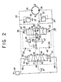
- Fig. 2 depicts a hydraulic circuit diagram that represents a first embodiment of the present invention.
- a pressure fluid discharged from a hydraulic pump 20 is supplied through a directional control valve 21 into a first and a second main circuit 22 and 23 which are connected to a first port 25 and a second port 26 of a hydraulic motor 24, respectively.
- a discharge path 20a of the hydraulic pump 20 is connected to a tank 27 via a principal relief valve 39.
- the directional control valve 21 described above is provided with a pump port 28, a tank port 29, and a first and a second actuator port 30 and 31.
- the pump port 28 is connected to the discharge path 20a of the hydraulic pump 20, the tank port 29 is connected to the tank, the first actuator port 30 is connected to the first main circuit 22, and the second actuator port 31 is connected to the second main circuit 23.
- the directional control valve 21 described above is of a pilot pressure switching type in which it may be held at its neutral position A by pair of springs 32 and 33, may be switched to its first position B under a fluid pressure applied at its first pressure receiving portion 34 and may be switched to its second position C under a fluid pressure applied at its second pressure receiving portion 35.
- the pump port 28 When the directional control valve 21 is held at its neutral position A , the pump port 28 will be in a fluid communication with both the first and second actuator ports 30 and 31 via a first and a second check valve 36 and 37, respectively, and also is in a fluid communication the tank port 29 via a restriction 38.
- the discharge pressure fluid of the hydraulic pump 20 is thus allowed to flow via the restriction 38 into the tank 27 when the directional control valve 21 is at the neutral state A , it will have a low pressure that is not affected by the principal relief valve 39 but is determined by the restriction 38. And, with this low pressure being applied to the first and second main circuits 22 and 23 via the first and second check valves 36 and 37, the pressure fluid in either the first or the second main circuit 22 or 23 will be blocked to flow towards the pump port 28 by the first and second check valves 36 and 37, thus the hydraulic motor 24 is held not in a rotary state if an external force is exerted thereon.
- the pump port 28 will be brought in a fluid communication with the first actuator port 30 and the tank port 29 will be brought in a fluid communication with the second actuator port 31.
- the hydraulic motor 24 Since the state is brought about thereby in which with the directional control valve 21 held at its first position B , the discharge pressure fluid from the hydraulic pump 20 is allowed to flow through the first main circuit 22 into the first port 25 of the hydraulic motor 24 and the pressure fluid from its second port 26 (the return fluid) is allowed to flow out thereof through the second main circuit 23 and the directional control valve 21 into the tank 27, the hydraulic motor 24 will be rotationally driven in one given rotary direction (shown by the arrow D ).
- the pump port 28 will be brought into a fluid communication with the second actuator port 31 and the tank port 29 will be brought into a fluid communication with the first actuator port 30.
- pilot pressure applying valve 40 will act to allow the pressures in the first and second main circuits 22 and 23 (i. e., the hydraulic motor driving pressures) to be applied, respectively, to the first and second pressure receiving portions 34 and 35 described above of the directional control valve 21.
- the pilot pressure applying valve 40 described above is provided with a first port 41, a second port 42, a third port 43, a fourth port 44 and a tank port 45.
- the first port 41 is connected via a first pilot circuit 46 to the first main circuit 22
- the second port 42 is connected via a second pilot circuit 47 to the first pressure receiving portion 34
- the third port 43 is connected via a third pilot circuit 48 to the second main circuit 23
- the fourth port 44 is connected via fourth pilot circuit 49 to the second pressure receiving portion 35
- the tank port 45 is connected to the tank 27. It may be noted also that there is provided a restriction 55 in each of the second and fourth pilot circuits 47 and 49.
- the pilot pressure applying valve 40 is here of an electromagnetically switching type in which it may be held at its neutral position by a first and a second spring 50 and 51, it may be switched to assume its first position G with a first solenoid 52 electrically energized and it may be switched to assume its second position H with a second solenoid 53 electrically energized.
- Each of the first and second solenoids 52 and 53 is adapted to be energized with an electric current by means of an operating unit 54 acted upon.
- pilot pressure applying valve 40 alternatively may be of a manually switching type in which it can be switched by a manual operation to assume its first and second position G and H , or may be of a pilot pressure switching type in which it can be switched likewise by another pilot pressure.
- the pilot pressure applying valve 40 When the pilot pressure applying valve 40 is held at its neutral position F , the first port 41 and the third port 43 will each be blocked whereas the second port 42 and the fourth port 44 will each be in a fluid communication with the tank port 45. Since the pressures at the first and second pressure receiving portions 34 and 35 of the directional control valve 21 are thus each relieved into the tank 27, the directional control valve 21 will then be switched to its neutral position A .
- the pilot pressure applying valve 40 when the pilot pressure applying valve 40 is switched to its first position G , the first port 41 and the second port 42 will be allowed to communicate with each other, the fourth port 44 and the tank port 45 will be allowed to communicate with each other, and the third port 43 will be blocked.
- the pilot pressure applying valve 40 when the pilot pressure applying valve 40 is switched to its second position H , the third port 43 and the fourth port 44 will be allowed to communicate with each other, the second port 42 and the tank port 45 will be allowed to communicate with each other, and the first port 41 will be blocked.
- the discharge pressure fluid from the hydraulic pump 20 will be supplied into the first main circuit 22 and the pressure fluid in the second main circuit 23 will be allowed to flow into the tank 27.
- the hydraulic motor 24 will be rotationally driven in the one rotary direction (shown by the arrow D ).
- a valve body 60 is formed therein with a first, large diameter spool bore 61 and a second, small diameter spool bore 62.
- the first spool bore 61 is formed with the various ports of the directional control valve 21, and has a first, large diameter spool 63 slidably inserted therein for establishing and blocking fluid communication between these ports, thus constituting the directional control valve 21.
- the second spool bore 62 is formed with the various ports of the pilot pressure applying valve 40, and has a second, small diameter spool 64 slidably inserted therein for establishing and blocking fluid communications between these ports, thus constituting the pilot pressure applying valve 40.
- the first spool 63 is formed thereon with a first small diameter portion 65 and a second small diameter portion 66.
- the first small diameter portion 65 is formed to communicate directly with the first actuator port 30 and to communicate via a first fluid bore 67 with the pump port 28. Further, the first check valve 36 is provided in the first fluid bore 67.
- the second small diameter portion 66 described above is formed to communicate directly with the second actuator port 31 and to communicate via a second fluid bore 68 with the pump port 28. Further, the second check valve 37 is provided in the second fluid bore 68.
- the first actuator port 30 is formed to communicate via a first fluid communication bore 69 with the first port 41
- the second actuator port 31 is formed to communicate via a second fluid communication bore 70 with the third port 43
- a said tank port 29 disposed at the left hand side and a said tank port 29 disposed at the right hand side are formed to communicate via a left hand side and a right hand side communication port 71 and 71, respectively, with a pair of interstices between the second spool bore 62 and the second spool 64 at the left hand side and the right hand side (which form a said tank port 45 at the left hand side and a said tank port 45 at the right hand side).
- the second port 42 is formed to communicate via a fourth communication port 72 with a first auxiliary port 73 in the first spool bore 61, the said first auxiliary port 73 is formed to communicate via a first, a second and a third fine bore 74, 75 and 76 formed in the first spool 63 in a succession with the first pressure receiving portion 34, where the first, second and third fine bores 74, 75 and 76 correspond to the restriction 55 which is shown in Fig. 2 as provided in the second pilot circuit 47.
- the fourth port 44 is formed to communicate via a fifth communication port 77 with a second auxiliary port 78 in the first spool bore 61, the said second auxiliary port 78 is formed to communicate via a fourth, a fifth and a sixth fine bore 79, 80 and 81 formed in the first spool 63 in a succession with the second pressure receiving portion 35, where the fourth, fifth and sixth fine bores 79, 80 and 81 correspond to the restriction 55 which is shown in Fig. 2 as provided in the fourth pilot circuit 49.
- the second spool 64 When neither the first solenoid 52 nor the second solenoid 53 is energized with an electric current, the second spool 64 will be balanced by the first and second springs 50 and 51 to assume its neutral position shown (i. e., the neutral position F in Fig. 2). Then, both the first port 41 and the third port 43 will be blocked, the second port 42 will be allowed to communicate via the right hand side tank port 45, the right hand side third communication bore 71 and the right hand side tank port 29 with the tank 27, and the fourth port 44 will be allowed to communicate via the left hand side tank port 45, the left hand side third communication port 71 and the left hand side tank port 29 with the tank 27.
- the first pressure receiving portion 34 will communicate via the first fine bore 74, the first auxiliary port 73, the right hand side fourth communication port 72 and the second port 42 with the tank 27, the second pressure receiving portion 35 to communicate via the fourth fine bore 79, the second auxiliary port 78, the left hand side fifth communication bore 77 and the fourth port 44 with the tank 27.
- the first spool 63 will take its neutral position shown (i. e., the neutral position A in Fig. 2).
- the first solenoid 52 is electrically energized to displace the second spool 64 rightwards from its neutral position shown,the first port 41 and the second port 42 will communicate with each other via the first small diameter portion 64a and the fourth port 44 will be brought into a fluid communication with the left hand side tank port 45. Then, the pilot pressure applying valve 50 will be switched to assume it first position G shown in Fig. 2.
- the pump port 28 will be brought into a fluid communication with the first actuator port 30 via the first small diameter portion 65 and the second actuator port 31 will be brought into a fluid communication with the tank port 29 via the second small diameter portion 66, thereby switching the directional control valve 21 to assume its first position B as shown in Fig. 2.
- the hydraulic motor 24 will be rotationally driven in the one rotary direction. Then, the first, second and third fine bores 74, 75 and 76 would have been in a fluid communication with the first auxiliary port 73.
- the hydraulic motor 24 in the state described earlier is driven, reversely by an external force, in the same direction with the result that the pressure in the first main circuit 22 is lowered, the pressure within the first pressure receiving portion 34 will be reduced as well. Since the first spool 63 is thus thrusted by the second spring 33 rightwards to restore its neutral position (i. e., a neutral position A as shown in Fig. 2), the communication between the second actuator port 31 and the left hand side tank port 29 will then be blocked, thus preventing the pressure fluid in the second main circuit 23 from flowing out thereof into the tank 27. Thence, the hydraulic motor 24 will be braked and cease rotating.
- the second spool 64 will be restored by means of the second spring 51 to its neutral position (i. e., a neutral position F as shown in Fig. 2). Then, since the fluid communication between the first port 41 and the second port 42 is blocked and the second port 42 is brought into fluid communication with a said tank port 45, the pressure fluid within the first pressure receiving portion 34 will be allowed to flow out thereof into the tank 27 via the first, second and third fine bores 74, 75 and 76. As a result, the first spool 63 will be thrusted by the second spring 33 and then displaced towards its neutral position, thus blocking the third fine bore 76. A further displacement thereof will block the second fine bore 72 and eventually the first spool 63 will be restored to its neutral position.
- the third port 43 and the fourth port 44 will be allowed to communicate with each other via the second small diameter portion 64b of the second spool 64 and the second port 42 will be brought into communication with the right hand side tank port 45. Then, the pilot pressure applying valve 40 will thereby be switched to its second position H as shown in Fig. 2.
- the hydraulic motor 24 in the state described earlier is driven, reversely by an external force, in the same direction with the result that the pressure in the second main circuit 23 is lowered, the pressure within the second pressure receiving portion 35 will be reduced as well. Since the first spool 63 is thus thrusted by the first spring 32 leftwards to restore its neutral position (i. e., a neutral position A as shown in Fig. 2), the communication between the first actuator port 30 and the right hand side tank port 29 will then be blocked, thus preventing the pressure fluid in the first main circuit 22 from flowing out thereof into the tank 27. Thence, the hydraulic motor 24 will be braked and cease rotating.
- the second spool 64 will be restored by means of the first spring 50 to its neutral position (i. e., a neutral position F as shown in Fig. 2). Then, since the fluid communication between the third port 43 and the fourth port 44 is blocked and the fourth port 44 is brought into fluid communication with a said tank port 45, the pressure fluid within the second pressure receiving portion 35 will be allowed to flow out thereof into the tank 27 via the fourth, fifth and sixth fine bores 79, 80 and 81. As a result, the first spool 63 will be thrusted by the first spring 32 and then displaced towards its neutral position, thus blocking the sixth fine bore 81. A further displacement thereof will block the fifth fine bore 80 and eventually the first spool 63 will be restored to its neutral position.
- each of the areas of openings between the first port 41 and the second port 42, between the second port 42 and the tank port 45, between the third port 43 and the fourth port 44 and between the fourth port 44 and the tank port 45, which may be created by the second spool 64, can be minimized, and the second spool 64 can then be also minimized in its diameter, it will be seen that the pilot pressure applying valve 40 could be rendered compact.
- a direct fluid communication may be established between the pump port 28 and the tank port 29 whereas there may be provided an unload valve 92 that is disposed at a location between the tank port 29 and the tank 27 and adapted to be unloaded in response to a reduced pressure thereat, for causing the pressure of the discharge fluid of the hydraulic pump 20 to be reduced when the directional control valve 21 is at the neutral position A and to be elevated up to the preset pressure for the principal relief valve 39 when the directional control valve 21 is switched to the first position B or the second position C .
- Fig. 5 The arrangement of Fig. 5 may be adopted, in which when the directional control valve 21 is set at the neutral position A the fluid communication between the pump port 28 and the tank port 29 is blocked and the principal relief valve 39 can then be a variable relief valve in which if a pressure is applied to a pressure receiving portion 90 it will have a high preset pressure level and if otherwise it will have a low preset pressure level.
- the pressure receiving portion 90 there is applied to the pressure receiving portion 90 via a shuttle valve 91 a pilot pressure that is effective in the second pilot circuit 47 or the fourth pilot circuit 49.
- pilot pressure applying valve 40 will be rendered compact and reduced in its area of installation.
- the directional control valve 21 herein is designed to be switched to its first position and its second position under the pressures at the first port 25 and at the the second port 26 of the hydraulic motor 24, respectively. Accordingly, when the hydraulic motor 24 is driven reversely by an external force, it can be seen that the pressure at its first port 25 or at its second port 26 will be allowed to drop, thereby restoring the directional control valve 21 to its neutral position. As a consequence, the check valve 36, 37 can be provided to prevent the pressure fluid from flowing out of the first port 25 or the second port 26 into the tank 27, hence permitting the hydraulic motor 24 to be braked and thus cease rotating.
- a pressure control means that allows the discharge pressure fluid from the hydraulic pump 20 to reduced when the directional control valve 21 is set at the neutral position and to be elevated when it is set to the first or second position. Any loss of the driving horse power which may ensue when the directional control valve is held at its neutral position can be drastically reduced. Also, the pressures both at the first port 26 and at the second port 26 of the hydraulic motor 24 which are effectively present when the directional control valve 21 is set at the neutral position can be utilized effectively as a pilot pressure such as to switch the directional control valve 21 to both the first and second positions, respectively.
Landscapes
- Engineering & Computer Science (AREA)
- General Engineering & Computer Science (AREA)
- Physics & Mathematics (AREA)
- Fluid Mechanics (AREA)
- Mechanical Engineering (AREA)
- Mining & Mineral Resources (AREA)
- Civil Engineering (AREA)
- Structural Engineering (AREA)
- Fluid-Pressure Circuits (AREA)
- Operation Control Of Excavators (AREA)
Abstract
Claims (7)
- Dispositif d'entraínement pour un moteur hydraulique qui comprend une vanne de commande directionnelle (21) pour alimenter d'une manière commandée un premier orifice (25) ou un deuxième orifice (26) d'un moteur hydraulique (24) en un fluide sous pression de refoulement provenant d'une pompe hydraulique (20) et pour ramener de manière commandée le fluide hydraulique provenant du deuxième ou premier orifice dans un réservoir (27), et une vanne (40) appliquant une pression pilote pour commander la vanne de commande directionnelle (21), et dans lequel :ladite vanne de commande directionnelle (21) est d'un type à commutation de pression pilote ayant une première et une deuxième partie (34, 35) recevant la pression et adaptée en vue de prendre sa position neutre (A) avec un moyen à ressort (32, 33), en vue de prendre sa première position (B) sous une pression hydraulique appliquée à ladite première partie recevant la pression (34) et de prendre sa deuxième position (C) sous une pression hydraulique appliquée à ladite deuxième partie (35) recevant la pression;le fluide sous pression de refoulement provenant de ladite pompe hydraulique (20) alimente par l'intermédiaire d'une vanne de non-retour (36, 37) les premier et deuxième orifices (25, 26) dudit moteur hydraulique (24) lorsque ladite vanne de commande directionnelle (21) est dans ladite position neutre (A);le fluide sous pression de refoulement provenant de ladite pompe hydraulique (20) alimente le premier orifice (25) dudit moteur hydraulique (24) et un fluide sous pression hydraulique dudit deuxième orifice (26) est autorisé à s'écouler de celui-ci dans le réservoir (27), lorsque ladite vanne de commande directionnelle (21) est dans ladite première position (B);le fluide sous pression de refoulement provenant de ladite pompe hydraulique (20) alimente le deuxième orifice (26) dudit moteur hydraulique (24) et un fluide sous pression hydraulique dudit premier orifice (25) est autorisé à s'écouler de celui-ci dans le réservoir (27), lorsque ladite vanne de commande directionnelle (21) est dans ladite deuxième position (C);ladite vanne appliquant une pression pilote (40) est munie de premier et deuxième moyens d'entraínement (52, 53) et adaptée en vue de prendre sa position neutre avec un moyen à ressort (50, 51) et adaptée à être commutée en vue de prendre respectivement sa première ou sa deuxième position (G, H) avec ledit premier ou ledit deuxième moyen d'entraínement (52, 53) afin d'appliquer une pression pilote à la première ou deuxième partie recevant la pression (34, 35) de ladite vanne de commande directionnelle (21);tant la première que la deuxième partie recevant la pression (34, 35) de ladite de commande directionnelle (21) sont chacune amenées en communication fluide avec le réservoir (27) lorsque ladite vanne (40) appliquant la pression pilote est dans ladite position neutre;le premier orifice (25) dudit moteur hydraulique (24) est amené en communication fluide avec la première partie (34) recevant la pression de ladite vanne de commande directionnelle (21) et ladite deuxième partie recevant la pression est amenée en communication fluide avec le réservoir (27), lorsque ladite vanne (40) appliquant la pression pilote est dans ladite première position (G); etle deuxième orifice (26) dudit moteur hydraulique (24) est amené en communication fluide avec la deuxième partie (35) recevant la pression de ladite vanne de commande directionnelle (21) et ladite première partie (34) recevant la pression est amenée en communication fluide avec le réservoir (27), lorsque ladite vanne (40) appliquant la pression pilote est dans ladite deuxième position (H).
- Dispositif d'entraínement de moteur hydraulique, selon la revendication 1, dans lequel un étranglement (38) est prévu à chaque fois dans un circuit pour établir une communication fluide entre la première partie (34) recevant la pression de ladite vanne de commande directionnelle (21) et ladite vanne (40) appliquant la pression pilote et dans un circuit pour établir une communication fluide entre ladite deuxième partie (35) recevant la pression et ladite vanne (40) appliquant la pression pilote.
- Dispositif d'entraínement de moteur hydraulique, selon la revendication 1 ou la revendication 2, qui comprend de plus un moyen de commande de pression répondant à ladite vanne de commande directionnelle (21) afin de provoquer un abaissement de la pression hydraulique du fluide de refoulement dudit moteur hydraulique (24) lorsqu'elle est amenée à ladite position neutre (A) et une augmentation de ladite pression hydraulique lorsque ladite vanne de commande directionnelle (21) est commutée en vue de prendre ladite première ou deuxième position (B ou C).
- Dispositif d'entraínement de moteur hydraulique, selon la revendication 3, dans lequel ledit moyen de commande de pression est prévu dans une voie (20a) de refoulement de fluide sous pression dudit moteur hydraulique (24) et constitué avec une vanne de détente principale (39) ayant une haute pression qui y est préréglée et répondant à ladite vanne de commande directionnelle (21) de sorte à autoriser une partie du fluide sous pression de refoulement dans ladite voie (20a) de refoulement de s'écouler hors de celle-ci par l'intermédiaire d'un étranglement (38) dans le réservoir (27), lorsqu'elle est commutée vers ladite position neutre (A).
- Dispositif d'entraínement de moteur hydraulique, selon la revendication 3, dans lequel ledit moyen de commande de pression est prévu dans une voie (20a) de refoulement de fluide sous pression dudit moteur hydraulique (24) et constitué avec une vanne (39) de détente principale ayant une haute pression qui y est préréglée et répondant à ladite vanne de commande directionnelle (21) de sorte à autoriser une partie du fluide sous pression de refoulement dans ladite voie (20a) de refoulement de s'écouler dans le circuit d'évacuation muni d'une vanne de décharge ayant une faible pression qui y est préréglée, lorsqu'elle est commutée dans ladite position neutre (A).
- Dispositif d'entraínement de moteur hydraulique, selon la revendication 3, dans lequel ledit moyen de commande de pression est prévu dans une voie (20a) de refoulement de fluide sous pression dudit moteur hydraulique (24) et constitué avec une vanne de détente (39) principale ayant une haute et faible pressions qui y sont préréglées, lesquelles sont établies de manière variable lorsqu'une pression pilote devient respectivement efficace et inefficace envers une partie recevant la pression pilote de ladite vanne de détente principale (39), et ladite partie recevant la pression pilote est reliée par l'intermédiaire d'une vanne navette (91) au premier et deuxième orifices (25, 26) dudit moteur hydraulique (24).
- Dispositif d'entraínement de moteur hydraulique, selon la revendication 1, la revendication 2 ou la revendication 3, dans lequel:ladite vanne de commande directionnelle (21) comprend:un corps de vanne (60);un premier alésage (61) pour tiroir cylindrique de grand diamètre formé dans ledit corps de vanne (60) et formé avec un orifice de pompe (28), un premier orifice (30) actionneur, un deuxième orifice (31) actionneur et un orifice de réservoir (29); etun premier tiroir cylindrique (63) de grand diamètre, inséré de façon à coulisser dans ledit premier alésage pour tiroir cylindrique de grand diamètre (61) et ayant respectivement une première partie recevant la pression (34) et une deuxième partie recevant la pression (35) à ses deux côtés opposés;ladite vanne (40) appliquant la pression pilote comprend:le corps de vanne (60);un deuxième alésage (62) pour tiroir cylindrique de grand diamètre formé dans ledit corps (60) de vanne et formé avec un premier orifice (41), un deuxième orifice (42), un troisième orifice (43), et un quatrième orifice (44), et un orifice de réservoir (45); etun deuxième tiroir (64) de petit diamètre, inséré de façon à coulisser dans ledit deuxième alésage pour tiroir cylindrique de petit diamètre (62) et adapté en vue de pouvoir coulisser dans ledit deuxième alésage (62) pour tiroir cylindrique à l'aide d'un premier et d'un deuxième moyen d'entraínement;une communication fluide peut être établie, à chaque fois, entre ledit premier orifice actionneur (30) et ledit premier orifice (41), entre ledit deuxième orifice actionneur (31) et ledit troisième orifice (43), entre ledit deuxième orifice (42) et ladite partie (34) recevant la pression, et entre ledit quatrième orifice (44) et ladite deuxième partie recevant la pression (35);ledit premier tiroir cylindrique (63) dans ladite vanne directionnelle (21) est adapté en vue d'être amené à sa position neutre (A) à l'aide d'un moyen à ressort (32, 33) afin de bloquer une communication fluide entre un desdits orifices et un autre là-dedans, en vue d'être amené à sa première position (B) sous une pression de fluide appliquée à ladite première partie (34) recevant la pression afin d'établir une communication fluide à chaque fois entre ledit orifice de pompe (28) et ledit premier orifice actionneur (30) et entre ledit deuxième orifice actionneur (31) et ledit orifice de réservoir (29) là-dedans, et en vue d'être amené à sa deuxième position (C) sous une pression de fluide appliqué à ladite deuxième partie (35) recevant la pression en vue d'établir une communication fluide à chaque fois entre ledit orifice de pompe (28) et ledit deuxième orifice actionneur (31) et entre ledit premier orifice actionneur (30) et ledit orifice de réservoir (29) là-dedans; etledit deuxième tiroir cylindrique (64) dans ladite vanne (40) appliquant la pression pilote est adapté en vue d'être amené à sa position neutre à l'aide d'un moyen à ressort afin de bloquer une communication fluide entre ledit premier orifice (41) et ledit troisième orifice (43) là-dedans et en vue d'établir une communication fluide à chaque fois entre ledit deuxième orifice (42) et ledit orifice de réservoir (45) et entre ledit quatrième orifice (44) et ledit orifice de réservoir (45) là-dedans, et en vue d'être amené à sa première position par ledit premier moyen d'entraínement afin d'établir une communication fluide à chaque fois entre ledit premier orifice (41) et ledit deuxième orifice (42) et entre ledit quatrième orifice (44)) et ledit orifice de réservoir (45) là-dedans, et en vue d'être amené à sa deuxième position par ledit deuxième moyen d'entraínement afin d'établir une communication fluide à chaque fois entre ledit troisième orifice (43) et ledit quatrième orifice (44) et entre ledit deuxième orifice (42) et ledit orifice de réservoir (45).
Applications Claiming Priority (4)
| Application Number | Priority Date | Filing Date | Title |
|---|---|---|---|
| JP6571895 | 1995-03-24 | ||
| JP06571895A JP3508955B2 (ja) | 1995-03-24 | 1995-03-24 | 油圧モータの駆動装置 |
| JP65718/95 | 1995-03-24 | ||
| PCT/JP1996/000764 WO1996030651A1 (fr) | 1995-03-24 | 1996-03-22 | Dispositif d'entrainement pour moteur hydraulique |
Publications (3)
| Publication Number | Publication Date |
|---|---|
| EP0833062A1 EP0833062A1 (fr) | 1998-04-01 |
| EP0833062A4 EP0833062A4 (fr) | 1998-07-01 |
| EP0833062B1 true EP0833062B1 (fr) | 2002-09-25 |
Family
ID=13295090
Family Applications (1)
| Application Number | Title | Priority Date | Filing Date |
|---|---|---|---|
| EP96906933A Expired - Lifetime EP0833062B1 (fr) | 1995-03-24 | 1996-03-22 | Dispositif d'entrainement pour moteur hydraulique |
Country Status (7)
| Country | Link |
|---|---|
| US (1) | US5930997A (fr) |
| EP (1) | EP0833062B1 (fr) |
| JP (1) | JP3508955B2 (fr) |
| KR (1) | KR100296535B1 (fr) |
| CN (1) | CN1183137A (fr) |
| DE (1) | DE69623958T2 (fr) |
| WO (1) | WO1996030651A1 (fr) |
Families Citing this family (16)
| Publication number | Priority date | Publication date | Assignee | Title |
|---|---|---|---|---|
| DE19609787A1 (de) * | 1996-03-13 | 1997-09-18 | Bosch Gmbh Robert | Hydrauliknotsteuerung für ein stufenloses Umschlingungsgetriebe mit erweitertem Handschaltventil |
| DE19859425A1 (de) * | 1998-12-22 | 2000-07-06 | Bosch Gmbh Robert | Hydrauliksteuerung für ein stufenlos veränderliches Getriebe |
| US6263670B1 (en) * | 1999-09-30 | 2001-07-24 | Sauer-Danfoss Inc. | Loop flushing circuit for lubricating rotating elements in a hydrostatic transmission module |
| JP3679749B2 (ja) * | 2001-10-19 | 2005-08-03 | サクサ株式会社 | 油圧装置 |
| US20040177610A1 (en) * | 2003-03-11 | 2004-09-16 | Hendrickson Barry M. | Broad range speed control for hydraulic motors |
| US20050281698A1 (en) * | 2004-06-21 | 2005-12-22 | 5Itech, Llc | Low speed, high torque rotary abutment motor |
| JP5049496B2 (ja) * | 2006-01-23 | 2012-10-17 | 株式会社小松製作所 | 制御回路 |
| JP4775812B2 (ja) * | 2006-01-24 | 2011-09-21 | 株式会社 神崎高級工機製作所 | Hst |
| CN101865173B (zh) * | 2010-07-21 | 2012-11-21 | 胡斌杰 | 一种液压马达控制阀 |
| CN102619803B (zh) * | 2012-03-31 | 2014-11-19 | 中联重科股份有限公司 | 并联阀组、液压控制回路和辅助装置 |
| JP5923415B2 (ja) * | 2012-09-11 | 2016-05-24 | Kyb株式会社 | ミキサドラムの駆動装置 |
| WO2014160189A2 (fr) * | 2013-03-14 | 2014-10-02 | Diversified Products, LLC | Système d'énergie mobile auxiliaire et accessoire formant râtelier à outils |
| CN106382265A (zh) * | 2016-11-10 | 2017-02-08 | 扬州市江都永坚有限公司 | 一种集成式泵控液压单元 |
| US10900502B2 (en) * | 2017-08-25 | 2021-01-26 | Parker-Hannifin Corporation | Direct input pilot operated servo valve |
| KR102581960B1 (ko) * | 2021-07-28 | 2023-09-22 | 주식회사 모트롤 | 모터 |
| US11598353B1 (en) * | 2022-02-01 | 2023-03-07 | Sun Hydraulics, Llc | Pressure compensation valve with load-sense fluid signal generation and a reverse free flow configuration integrated therewith |
Family Cites Families (13)
| Publication number | Priority date | Publication date | Assignee | Title |
|---|---|---|---|---|
| JPS5469676A (en) * | 1977-11-12 | 1979-06-04 | Kawasaki Heavy Ind Ltd | Oil pressure control system |
| DE2845922C3 (de) * | 1978-10-21 | 1982-02-04 | G.L. Rexroth Gmbh, 8770 Lohr | Vorgesteuertes hydraulisches Wegeventil mit Verteilerfunktion |
| JPS56167903A (en) * | 1980-05-24 | 1981-12-23 | Hitachi Constr Mach Co Ltd | Hydraulic circuit of brake for hydraulic motor |
| JPS60260703A (ja) * | 1984-06-08 | 1985-12-23 | Toshiba Mach Co Ltd | 油圧制御装置 |
| US4694647A (en) * | 1986-03-28 | 1987-09-22 | Kabushiki Kaisha Komatsu Seisakusho | Hydraulic circuit system for use in hydraulically operated vehicles |
| KR930010906B1 (ko) * | 1989-12-14 | 1993-11-17 | 니뽄 에어브레이크 가부시끼가이샤 | 유압 모터의 제어 회로 |
| JP3001229B2 (ja) * | 1990-06-18 | 2000-01-24 | 帝人製機株式会社 | リリーフ機能付き流体装置 |
| US5062266A (en) * | 1990-08-23 | 1991-11-05 | Kabushiki Kaisha Kobe Seiko Sho | Slewing control device for crane |
| JPH04133003A (ja) * | 1990-09-25 | 1992-05-07 | Matsushita Electric Works Ltd | 光学多層選択反射膜 |
| DE4102203A1 (de) * | 1991-01-25 | 1992-07-30 | Linde Ag | Hydraulisches antriebssystem |
| JPH04133003U (ja) * | 1991-06-03 | 1992-12-10 | 株式会社小松製作所 | 流体ブレーキ装置 |
| US5709083A (en) * | 1996-08-15 | 1998-01-20 | Caterpillar Inc. | Hydraulic swing motor deceleration control |
| CN112839533B (zh) | 2018-09-19 | 2025-04-04 | 日本烟草产业株式会社 | 香味生成装置、电源单元、控制香味生成装置的方法以及计算机可读取的记录介质 |
-
1995
- 1995-03-24 JP JP06571895A patent/JP3508955B2/ja not_active Expired - Fee Related
-
1996
- 1996-03-22 KR KR1019970706621A patent/KR100296535B1/ko not_active Expired - Fee Related
- 1996-03-22 EP EP96906933A patent/EP0833062B1/fr not_active Expired - Lifetime
- 1996-03-22 US US08/913,717 patent/US5930997A/en not_active Expired - Fee Related
- 1996-03-22 CN CN96193613A patent/CN1183137A/zh active Pending
- 1996-03-22 DE DE69623958T patent/DE69623958T2/de not_active Expired - Fee Related
- 1996-03-22 WO PCT/JP1996/000764 patent/WO1996030651A1/fr not_active Ceased
Also Published As
| Publication number | Publication date |
|---|---|
| JPH08261204A (ja) | 1996-10-08 |
| DE69623958T2 (de) | 2003-06-05 |
| US5930997A (en) | 1999-08-03 |
| CN1183137A (zh) | 1998-05-27 |
| EP0833062A4 (fr) | 1998-07-01 |
| DE69623958D1 (de) | 2002-10-31 |
| EP0833062A1 (fr) | 1998-04-01 |
| KR100296535B1 (ko) | 2001-10-25 |
| KR19980703217A (ko) | 1998-10-15 |
| WO1996030651A1 (fr) | 1996-10-03 |
| JP3508955B2 (ja) | 2004-03-22 |
Similar Documents
| Publication | Publication Date | Title |
|---|---|---|
| EP0833062B1 (fr) | Dispositif d'entrainement pour moteur hydraulique | |
| JP3785159B2 (ja) | 産業用トラック用の電気油圧式昇降制御装置 | |
| EP0765772A1 (fr) | Circuit de commande mobile pour dispositif mobile a entrainement hydraulique | |
| US3956891A (en) | Closed center hydraulic system for lift trucks | |
| JP3535255B2 (ja) | 油圧駆動制御装置 | |
| US6112521A (en) | Backpressure control circuit for hydraulic drive device | |
| JPH1078006A (ja) | 減速制御装置 | |
| EP0793022A1 (fr) | Dispositif de frein hydraulique | |
| JP2000516885A (ja) | 電気油圧式の制御装置 | |
| US5839885A (en) | Capacity control apparatus for a variable capacity hydraulic pump | |
| US5584227A (en) | Variable priority device | |
| JP3802989B2 (ja) | 作業車両の油圧回路 | |
| JP3978292B2 (ja) | 走行駆動装置 | |
| JP4325851B2 (ja) | Hst走行駆動装置 | |
| EP0704630B1 (fr) | Valve de séquence variable pour engins de construction lourds | |
| JP3603007B2 (ja) | 可変容量型油圧モータの容量制御装置 | |
| US7117670B2 (en) | Control device | |
| JP3907292B2 (ja) | 油圧サーボ機構のパイロット圧力制御装置 | |
| JPH04285303A (ja) | ロ−ドセンシング油圧回路 | |
| JPS6378930A (ja) | 油圧シヨベルの走行油圧回路 | |
| JPH0735161Y2 (ja) | 油圧走行車両等の液圧ポンプ制御装置 | |
| JP3181929B2 (ja) | 油圧制御装置 | |
| JPS612904A (ja) | 液圧装置 | |
| JP2605795B2 (ja) | パイロット操作流体回路 | |
| JP3739518B2 (ja) | 油圧走行装置のブレーキ装置 |
Legal Events
| Date | Code | Title | Description |
|---|---|---|---|
| PUAI | Public reference made under article 153(3) epc to a published international application that has entered the european phase |
Free format text: ORIGINAL CODE: 0009012 |
|
| 17P | Request for examination filed |
Effective date: 19970918 |
|
| AK | Designated contracting states |
Kind code of ref document: A1 Designated state(s): DE GB IT Kind code of ref document: A1 Designated state(s): DE |
|
| A4 | Supplementary search report drawn up and despatched | ||
| AK | Designated contracting states |
Kind code of ref document: A4 Designated state(s): DE GB IT |
|
| 17Q | First examination report despatched |
Effective date: 20000731 |
|
| GRAG | Despatch of communication of intention to grant |
Free format text: ORIGINAL CODE: EPIDOS AGRA |
|
| GRAG | Despatch of communication of intention to grant |
Free format text: ORIGINAL CODE: EPIDOS AGRA |
|
| GRAH | Despatch of communication of intention to grant a patent |
Free format text: ORIGINAL CODE: EPIDOS IGRA |
|
| GRAH | Despatch of communication of intention to grant a patent |
Free format text: ORIGINAL CODE: EPIDOS IGRA |
|
| GRAA | (expected) grant |
Free format text: ORIGINAL CODE: 0009210 |
|
| RBV | Designated contracting states (corrected) |
Designated state(s): DE |
|
| AK | Designated contracting states |
Kind code of ref document: B1 Designated state(s): DE |
|
| REF | Corresponds to: |
Ref document number: 69623958 Country of ref document: DE Date of ref document: 20021031 |
|
| PLBE | No opposition filed within time limit |
Free format text: ORIGINAL CODE: 0009261 |
|
| STAA | Information on the status of an ep patent application or granted ep patent |
Free format text: STATUS: NO OPPOSITION FILED WITHIN TIME LIMIT |
|
| 26N | No opposition filed |
Effective date: 20030626 |
|
| PG25 | Lapsed in a contracting state [announced via postgrant information from national office to epo] |
Ref country code: DE Free format text: LAPSE BECAUSE OF NON-PAYMENT OF DUE FEES Effective date: 20031001 |