EP0833208A2 - Dispositif porte-objet - Google Patents
Dispositif porte-objet Download PDFInfo
- Publication number
- EP0833208A2 EP0833208A2 EP97114842A EP97114842A EP0833208A2 EP 0833208 A2 EP0833208 A2 EP 0833208A2 EP 97114842 A EP97114842 A EP 97114842A EP 97114842 A EP97114842 A EP 97114842A EP 0833208 A2 EP0833208 A2 EP 0833208A2
- Authority
- EP
- European Patent Office
- Prior art keywords
- stage
- measurement
- object table
- mounting object
- plane
- Prior art date
- Legal status (The legal status is an assumption and is not a legal conclusion. Google has not performed a legal analysis and makes no representation as to the accuracy of the status listed.)
- Ceased
Links
Images





Classifications
-
- G—PHYSICS
- G03—PHOTOGRAPHY; CINEMATOGRAPHY; ANALOGOUS TECHNIQUES USING WAVES OTHER THAN OPTICAL WAVES; ELECTROGRAPHY; HOLOGRAPHY
- G03F—PHOTOMECHANICAL PRODUCTION OF TEXTURED OR PATTERNED SURFACES, e.g. FOR PRINTING, FOR PROCESSING OF SEMICONDUCTOR DEVICES; MATERIALS THEREFOR; ORIGINALS THEREFOR; APPARATUS SPECIALLY ADAPTED THEREFOR
- G03F9/00—Registration or positioning of originals, masks, frames, photographic sheets or textured or patterned surfaces, e.g. automatically
- G03F9/70—Registration or positioning of originals, masks, frames, photographic sheets or textured or patterned surfaces, e.g. automatically for microlithography
- G03F9/7003—Alignment type or strategy, e.g. leveling, global alignment
- G03F9/7023—Aligning or positioning in direction perpendicular to substrate surface
- G03F9/7026—Focusing
-
- G—PHYSICS
- G03—PHOTOGRAPHY; CINEMATOGRAPHY; ANALOGOUS TECHNIQUES USING WAVES OTHER THAN OPTICAL WAVES; ELECTROGRAPHY; HOLOGRAPHY
- G03F—PHOTOMECHANICAL PRODUCTION OF TEXTURED OR PATTERNED SURFACES, e.g. FOR PRINTING, FOR PROCESSING OF SEMICONDUCTOR DEVICES; MATERIALS THEREFOR; ORIGINALS THEREFOR; APPARATUS SPECIALLY ADAPTED THEREFOR
- G03F7/00—Photomechanical, e.g. photolithographic, production of textured or patterned surfaces, e.g. printing surfaces; Materials therefor, e.g. comprising photoresists; Apparatus specially adapted therefor
- G03F7/70—Microphotolithographic exposure; Apparatus therefor
- G03F7/70691—Handling of masks or workpieces
- G03F7/707—Chucks, e.g. chucking or un-chucking operations or structural details
-
- G—PHYSICS
- G03—PHOTOGRAPHY; CINEMATOGRAPHY; ANALOGOUS TECHNIQUES USING WAVES OTHER THAN OPTICAL WAVES; ELECTROGRAPHY; HOLOGRAPHY
- G03F—PHOTOMECHANICAL PRODUCTION OF TEXTURED OR PATTERNED SURFACES, e.g. FOR PRINTING, FOR PROCESSING OF SEMICONDUCTOR DEVICES; MATERIALS THEREFOR; ORIGINALS THEREFOR; APPARATUS SPECIALLY ADAPTED THEREFOR
- G03F7/00—Photomechanical, e.g. photolithographic, production of textured or patterned surfaces, e.g. printing surfaces; Materials therefor, e.g. comprising photoresists; Apparatus specially adapted therefor
- G03F7/70—Microphotolithographic exposure; Apparatus therefor
- G03F7/70691—Handling of masks or workpieces
- G03F7/70716—Stages
-
- G—PHYSICS
- G03—PHOTOGRAPHY; CINEMATOGRAPHY; ANALOGOUS TECHNIQUES USING WAVES OTHER THAN OPTICAL WAVES; ELECTROGRAPHY; HOLOGRAPHY
- G03F—PHOTOMECHANICAL PRODUCTION OF TEXTURED OR PATTERNED SURFACES, e.g. FOR PRINTING, FOR PROCESSING OF SEMICONDUCTOR DEVICES; MATERIALS THEREFOR; ORIGINALS THEREFOR; APPARATUS SPECIALLY ADAPTED THEREFOR
- G03F9/00—Registration or positioning of originals, masks, frames, photographic sheets or textured or patterned surfaces, e.g. automatically
- G03F9/70—Registration or positioning of originals, masks, frames, photographic sheets or textured or patterned surfaces, e.g. automatically for microlithography
- G03F9/7003—Alignment type or strategy, e.g. leveling, global alignment
-
- G—PHYSICS
- G03—PHOTOGRAPHY; CINEMATOGRAPHY; ANALOGOUS TECHNIQUES USING WAVES OTHER THAN OPTICAL WAVES; ELECTROGRAPHY; HOLOGRAPHY
- G03F—PHOTOMECHANICAL PRODUCTION OF TEXTURED OR PATTERNED SURFACES, e.g. FOR PRINTING, FOR PROCESSING OF SEMICONDUCTOR DEVICES; MATERIALS THEREFOR; ORIGINALS THEREFOR; APPARATUS SPECIALLY ADAPTED THEREFOR
- G03F9/00—Registration or positioning of originals, masks, frames, photographic sheets or textured or patterned surfaces, e.g. automatically
- G03F9/70—Registration or positioning of originals, masks, frames, photographic sheets or textured or patterned surfaces, e.g. automatically for microlithography
- G03F9/7003—Alignment type or strategy, e.g. leveling, global alignment
- G03F9/7023—Aligning or positioning in direction perpendicular to substrate surface
- G03F9/7034—Leveling
Definitions
- the present invention concerns an exposure apparatus used in photolithography processes in the manufacture of semiconductor devices, liquid crystal display devices, etc., and in particular concerns an exposure apparatus provided with a levelling device for matching the surface of the photosensitive substrate with the image formation plane of the projection optical system.
- the present invention also concerns a stage apparatus, more specifically, a stage apparatus which is provided with a No. 1 stage which is able to move in a specified direction along a guidance plane over an antivibration stage which is held horizontally via antivibration pads, and a No. 2 stage which is mounted on this No. 1 stage and can be tilt-driven.
- the stage apparatus of the present invention can be used effectively as a stage for the positioning of photosensitive substrates in exposure devices, etc.
- an exposure apparatus in which a pattern formed on a photomask (hereinafter referred to as mask) or reticle is projected and exposed on each shot area of a photosensitive substrate such as a semiconductor wafer or glass plate, etc., which has been coated with a photosensitive agent such as photoresist via a projection optical system.
- a photomask hereinafter referred to as mask
- reticle is projected and exposed on each shot area of a photosensitive substrate such as a semiconductor wafer or glass plate, etc., which has been coated with a photosensitive agent such as photoresist via a projection optical system.
- a so-called step-and-repeat type exposure apparatus wherein the photosensitive substrate is mounted on a substrate stage which is moveable in two dimensions, and the operation of exposing the pattern image of the mask on each shot area of the photosensitive substrate is repeated by stepping the photosensitive substrate using this substrate stage, and, in particular, reductive projection type exposure apparatuses have often been used.
- step-and-scan type exposure apparatuses have been used in which pattern exposure is performed on each shot area of the photosensitive substrate by reductive projection and, by means of a scanning exposure system, movement is performed between the shot areas in a stepping mode.
- a projection optical system which has a large numerical aperture and a shallow focal depth is used in the exposure apparatus, in order to transcribe a fine pattern with high resolution, levelling control, whereby the angle of inclination of the photosensitive substrate surface is matched so as to be parallel with the angle of inclination of the image formation plane of the projection optical system, and autofocus control, whereby the height (focal point position) of the surface of the photosensitive substrate is matched with the position of the image formation plane of the projection optical system are necessary.
- the sensor which measures the height position of the photosensitive substrate in the Z direction is fixed on the apparatus main body and is unable to move. Accordingly, in order to measure the Z direction positions of several points on the photosensitive substrate surface, the photosensitive substrate is moved by means of the substrate stage, and the multiple points on the photosensitive substrate are taken to the measurement point of the sensor in sequence.
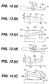
- FIG. 13 Here, the action of performing levelling control based on sensor measurement values having measurement points in the positions indicated by the broken line are explained making the running direction of the substrate stage the X direction and the direction parallel to the optical axis the Z direction.
- FIGs. 13(a) through (c) consists of diagrams explaining the concept of levelling control in the case where there is no displacement of the substrate running in the Z direction and
- FIGs. 13(d) through (f) consists of diagrams explaining the concept of levelling control when the running of the substrate stage has displacement in the Z direction.
- the photosensitive substrate is positioned in the position indicated by the solid line by means of the movement of the substrate stage (85) and the height position of point P 1 of the photosensitive substrate surface SF 1 is measured.
- the X coordinate of point P 1 is X 1
- the height measurement position at this time is made Z 1 .
- the photosensitive substrate (80) is moved to a different position on an imaginary line as indicated by the arrow by the movement of the substrate stage and the height position of another point P 2 on the photosensitive substrate surface SF 1 is measured.
- the X coordinate of point P 2 is made X 2
- the height measurement value is made Z 2 .
- the exposure apparatus recognizes that the surface SF 1 of the photosensitve substrate is inclined as shown in FIG. 13(b). Accordingly, as shown in FIG. 13(c), levelling control is performed so that the mounting object table 81 upon which the photosensitive substrate 80 is mounted is inclined by operating the levelling mechanisms 82a, 82b of the substrate stage, and the surface SF 1 of the photosensitive substrate 80 becomes horizontal. In this way, if the running of the substrate stage 85 becomes displaced in the Z direction, a conventional exposure apparatus can perform suitable levelling control based on the height measurement values.
- the photosensitive substrate 87 is moved by the movement of the substrate stage up to a position indicated by the broken line as shown by the arrows, and the height of another point P 4 on the photosensitive substrate surface SF 2 is measured.
- the photosensitive substrate 87 is moved in the Z direction as well, and the measurement value of the height of point P 4 is assumed to become Z 4 .
- the X coordinate of point P 4 is X 4 .
- the exposure apparatus recognizes that the surface SF 2 of the photosensitive substrate is inclined as indicated in FIG. 13(e), despite the fact that it is actually horizontal. Accordingly, control is performed so that the levelling mechanism 82a, 82b of the substrate stage 85 are operated, the mounting object table 81 upon which the photosensitive substrate 87 is mounted is tilted, and the height position Z 3 of point P 3 and the height position Z 4 of point P 4 are made equal. As a result, as shown in FIG. 13d, faulty levelling control is performed, and the surface SF 2 of the photosensitive substrate 87 ceases to be horizontal.
- an exposure apparatus In the past, in the manufacture of semiconductor elements or liquid crystal display elements, etc., by photolithographic processes, an exposure apparatus has been used wherein the image of a pattern formed on a mask or reticle is transferred via a projection optical system onto an exposure target substrate such as a wafer or glass plate.
- a stage apparatus is used wherein a sample stage in which movement of 3 axes, movement in the up-down direction (Z), rotation around the X axis, and rotation around the Y axis, or on 4 axes, adding rotation on a Z axis is mounted on an XY stage which is able to move within a 2-dimensional plane in perpendicular biaxial directions (normally the XY biaxial directions).
- the sample stand as a result can have positional and attitude control of 5 degrees of freedom or 6 degrees of freedom, and the position of the sample stand in the XY 2-dimensional direction is measured with high accuracy by means of a lightwave interferometer, generally a laser interferometer, via a reflecting mirror (moving mirror) fixed on the sample stand.
- a lightwave interferometer generally a laser interferometer
- a light source, reticle stage, projection optical system, reflecting mirror (fixed mirror) which forms the light generating part and standard of the laser interferometer, a focus detection system, which measures positional displacement of the focal planes of the exposure target substrate and projection optical system in the optical axis direction, and a leveling detection system, which measures the inclination of the exposure target substrate and focal plane (image formation plane), etc., are mounted on a stand to which the stage base is rigidly connected.
- the XY stage is moved 2-dimensionally in the XY plane, the exposure position (shot region) of the exposure target substrate is positioned in the pattern projection position of the projection optical system, and next, or at the same time as the XY movement, the sample stand is Z-driven based upon the measurement results of the focus detection system so as to enter the region of the focal depth of the projection optical system, simultaneously the inclination of the sample stand is adjusted based upon the measurement results of the leveling detection system so that the exposure target substrate and image formation plane will be parallel, and when all deviations have entered allowable levels, exposure is performed.
- the sample stand is tilted, but since the moving mirror is also tilted together with the sample stand at this time, the angle formed by the laser beam optical axis from the interferometer and the moving mirror reflecting face changes. Specifically, the laser beam is no longer perpendicularly incident to the moving mirror reflecting face, and as a result error is produced in the XY coordinates of the sample stand as measured by the laser interferometer.
- the principal error is generally referred to as Abbe error and cosing error
- the error has been obtained by means of calculation assuming the inclination ⁇ of the sample stand that has been detected by the measurement device mounted on the XY stage as being the same as the ⁇ , and error has been eliminated by correcting the position of the XY stage or the position of the reticle.
- the fixed base upon which the XY stage and its stage base are mounted is held horizontally by means of antivibration pads, so that there is some inclination of the fixed base with regard to an absolute standard due to the movement of the center of gravity accompanying movement of the XY stage, in such cases, the necessity arises to position the XY stage taking into consideration the effects of this inclination as well.
- the present invention is directed to an exposure apparatus that substantially obviates one or more of the problems due to limitations and disadvantages of the related art.
- the present invention was produced in light of these problems in the prior art and has the object of offering an exposure apparatus which is able to perform levelling without being affected by displacement in the Z direction due to running of the substrate stage.
- the present invention also has the purpose of offering an exposure apparatus which is able to perform exposure with regard to shots on the photosensitive substrate periphery without the occurrence of focal point displacement.
- levelling control can be performed eliminating the influence of Z direction displacement of the photosensitive substrate caused by running of the substrate stage, high precision levelling control becomes possible, and increased yield in device manufacturing can be designed.
- the Z direction displacement amount can be predicted when the substrate stage shifts in 2-dimensional directions, correction in the Z direction can be performed with high speed and high accuracy.
- highly accurate focusing can be performed even in cases when exposure is performed using the focal point detection position of the adjacent shot area.
- the purposes are achieved by measuring in advance the Z direction displacement caused by the running of the substrate stage and storing this in a memory.
- the main cause of this type of Z direction displacement due to running of the substrate stage is manufacturing error in the stage materials, and the Z direction displacment in an arbitrary coordinate point on the XY plane in which this is a factor is stable over a long period of time. Therefore, using a standard substrate, etc., for which the degree of parallelism of the front and back surfaces is already known, the Z direction displacement based on the running of the substrate stage is measured for multiple points on the XY plane in advance and stored in a memory. Since the Z direction position of the substrate stage in the XY plane varies in each apparatus, it is necessary to perform this measurement for each apparatus.
- the true inclination of the photosensitive substrate surface can be obtained, and levelling control is performed based on this inclination.
- the present invention also concerns a stage apparatus wherein the sample stage can be positioned accurately in a target position even when a difference occurs in the relative angle of the measurement beam optical axis and the moving mirror reflecting face, without being subject to the effect thereof.
- an exposure apparatus includes a projection optical system, which projects a pattern formed on a mask on a photosensitive substrate, a mounting object table, which holds the photosensitive substrate, a positioning stage, which positions the mounting object table along a 2-dimensional movement coordinate system, a stage coordinate measurement device, which detects the position of the mounting object table in the 2-dimensional movement coordinate system, a height measurement device, which detects the deviation in the optical axis direction of the projection optical system from the surface of the photosensitive substrate to a specified standard surface in a measurement point fixed with regard to the 2-dimensional movement coordinate system, a levelling device, which adjusts the inclination of the mounting object table with regard to the positioning stage, a computation device, which calculates the control amount of the levelling device necessary to match the surface of the photosensitive substate with the standard plane, and a control device, which controls the levelling device based on the computation results of the computation device, the exposure apparatus characterized by the fact that a
- FIG. 1 is a schematic diagram of one example of an exposure apparatus in accordance with the present invention.
- Illumination light IL for exposure from a light source system 1 including a light source, such as an excimer laser or mercury lamp which projects DUV light and an optical integrator, etc. illuminates the pattern of a mask 7 in a uniform intensity distribution via a No. 1 lens 2, a mask blind (variable field aperture) 3, No. 2 lens 4, mirror 5, and main condenser lens 6.
- the alignment position of the mask blind 3 is nearly conjugate with the pattern formation plane of the mask 7, and the position and form of the illumination area 8 on the mask 7 is determined by the position and form of the opening of the mask blind 3.
- the mask 7 is held on a mask stage 9.
- a projection optical system 11 By means of a projection optical system 11 the pattern image of the mask 7 is projected and exposed on the shot area 13 of the photosensitive substrate 12, which is coated with a photoresist.
- the Z axis is extended parallel to the optical axis of the projection exposure system 11, the X axis parallel to the paper plane in FIG. 1 within the 2-dimensional plane perpendicular to that optical axis, and the Y axis perpendicular to the paper plane in FIG. 1.
- the photosensitive substrate 12 is held on a mounting object table 14 via a photosensitive substrate holder not shown in the figure.
- the mounting object table 14 is mounted on a positioning stage which can move freely within the XY coordinate system via 3 actuators 16A through 16C, which move in the Z direction.
- the positioning stage is composed of a Y stage 15Y and X stage 15X, and the Y stage 15Y is mounted so as to be able to move in the Y direction in a feeding screw mode, for example, on the X stage 15X.
- the X stage 15X is mounted on the apparatus base 17 so as to be able to move in the X direction in a feeding screw mode, for example.
- the main control system 20 controls the operation of the X stage 15X, Y stage 15Y, and mounting object table 14 through the substrate stage drive system 24.
- FIG. 6 shows a cross-sectional diagram of the actuator 16A.
- a drive mechanism housing 40 is fixed on the Y stage 15Y in FIG. 1
- a feeding screw 41 is housed inside the drive mechanism housing 40 so as to be able to turn
- a rotor encoder 43 for rotational angle detection is connected to the left end of the feeding screw 41 via a coupling 42
- a rotary motor 45 is connected to the right end of the feeding screw 41 via a coupling 44.
- a nut 39 is screwed onto the feeding screw 41, an inclined plane part 36A having the upper end inclined is fixed to the nut 39 via a support column 38, and the rotor 36B is in contact with the upper end of the inclined plane part 36A.
- the rotor 36B is embedded so as to be able to turn within the mounting object table 14 in FIG. 1 and to be unable to move in the lateral direction.
- the inclined plane part 36A is held so that it is able to move in a direction parallel to the feeding screw 41 along a linear guide 37.
- the drive control signal from the substrate stage control system 24 in FIG. 1 is supplied to the rotary motor 45 and the rotary motor 45 receives the control signal and turns the feeding screw 41.
- the nut 39 is moved in the X direction along the feeding screw 41 and the inclined plane part 36A also moves along the feeding screw 41.
- the rotor 36B which is in contact with the upper end of the inclined plane part 36A, is displaced in the upper or lower direction (Z direction) with regard to the drive mechanism housing 40 while rotating.
- the displacement amount of the rotor 36B in the up-down direction is detected.
- the other actuators 16B and 16C have a similar structure.
- the actuators 16A through 16C in addition to the mode which uses a rotary motor as shown in FIG. 6, may also be constituted so as to use, for example, a laminated piezoelectric element (piezo element), etc.
- piezo element piezo element
- linear encoder can be used as the encoder for detecting the position in the Z direction.
- multipoint AF sensor which detects the position of the surface of the photosensitive substrate 12 in the Z direction (focal point position)
- Detection light having non-photosensitivity with regard to the photoresist is projected from the light source 26 of the multipoint AF sensor 25.
- the detection light illuminates multiple slits inside the light transmission slit plate 28 via the condenser lens 27, and the images of these slits are projected via the object lens 29 onto nine measurement points P 11 through P 33 on shot areas 13 on the photosensitive substrate 12 diagonal to the optical axis of the projection optical system 11.
- the images of the slits of the light transmission slit plate 28 are formed on the surface of the photosensitive substrate 12 by the object lens 29.
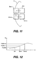
- FIG. 2 shows the arrangement of measurement points on the photosensitive substrate 12; as shown in the figure, a total of nine measurement point P 11 through P 33 , 3 rows ⁇ 3 columns, are set within the shot area 13.
- the average shot position within the shot area 13 is obtained from the information of the focal point positions at the nine measurement points within the shot area 13.
- the reflected light from these measurement points is condensed on a vibrating slit plate 31 via a condenser lens 30, and the slit images projected on these measurement points are again formed on the vibrating slit plate 31.
- the vibrating slit plate 31 is vibrated in a specified direction by means of a vibrator 32 which is driven by means of a drive signal DS from the main control system 20.
- the light passing through the multiple light slits of the vibrating slit plate 31 undergoes photoelectric conversion by means of multiple photoelectric conversion elements on the photoelectric detector 33, and these photoelectric conversion signals are supplied to a signal processing system 34, and are supplied to the main control unit 20 after signal processing.
- FIG. 3 is a schematic diagram of the light transmission slit plate 28 in FIG. 1.
- slits 28 11 through 28 33 are formed in positions corresponding to the measurement points P 11 through P 33 , respectively, on the photosensitive substrate in FIG. 2.
- slits 31 11 through 31 33 are formed in positions corresponding to the measurement points P 11 through P 33 on the photosensitive substrate in FIG. 2 in the vibrating slit plate 31 in FIG. 1 as well, and the vibrating slit plate 31 is vibrated by means of a vibrator 32 in a measurement direction perpendicular to the longitudinal direction of the slits.
- FIG. 5 is a diagram showing the photoelectric detector 33 and signal processing system 34 in FIG. 1.
- Light reflected from the measurement points P 11 through P 13 in FIG. 2 and passing through the corresponding slits in the vibrating slit plate 31 are projected into the first row of photoelectric conversion elements 33 11 through 33 13 on the photoelectric convertor 33.
- Light reflected from the measurement points P 21 through P 23 , P 31 through P 33 in FIG. 2 and passing through the corresponding slits in the vibrating slit plate 31 is projected into the respective photoelectric conversion elements 33 21 through 33 23 , 33 31 through 33 33 in the second and third rows of the photoelectric converter 33.
- the detection signals from the photoelectric conversion elements 33 11 through 33 33 are supplied via amplifiers 46 11 through 46 33 to synchronous commutators 47 11 through 47 33 .
- the synchronous commutators 47 11 through 47 33 by the synchronous commutation of the input detection signals using a drive signal DS for the vibrator 32, produces a focus signal which changes nearly proportionally to the focal point position of the corresponding measurement points within a specified range.
- the focus signals output from the synchronous commutators 47 11 through 47 33 undergo calibration so as to become 0 when the corresponding measurement point matches the image formation plane (best focus plane) of the projection optical system 11.
- the focus signals output from the synchronous commutators 47 11 through 47 33 are supplied in parallel to the multiplexer 48.
- the multiplexer 48 synchronously with a changeover signal from the microprocessor (MPU) 50 in the main control system 20, supplies focus signals selected in order from the focus signals supplied to the analog/digital (A/D) converter 49, and the digital focus signals output from the A/D converter 49 are stored sequentially in the memory 51 of the main control system 20.
- MPU microprocessor
- FIG. 7 shows the drive system of the three actuators 16A through 16C.
- Digital focus signals which indicate the focal point positions at measurement points P 11 through P 33 in FIG. 2 are stored, respectively, in addresses 51 11 through 51 33 in the memory 51 in the main control system 20. Focus signals read out from the addresses 51 11 through 51 33 are supplied in parallel to the focal point position calculator 52.
- the focal point position calculator 52 based on the 9 focus signals corresponding to the nine measurement points P 11 through P 33 , the focal point position z of the shot area 13, i.e., the amount of Z direction deviation from the best focus plane of the projection optical system 11, is obtained by calculations such as least square calculation, arithmetic mean, weighted average, etc.
- the calculation of the focal point position z by the least square method is performed as follows. If the deviations from the best focus obtained from the nine focus signals corresponding to nine measurement points P 11 through P 33 are called ⁇ Z 11 , ⁇ Z 12 , . . ., ⁇ Z 33 , respectively, the focal point position z is determined so that the value of the following numerical expression 1 is minimal.
- the focal point position z obtained in this way is supplied to the levelling computer 56 when levelling control is performed and is supplied to the actuator drive amount unit 57 when each shot exposure is performed.
- the displacement of the measurement point in the Z direction due to running of the substrate stage is measured in advance and stored as an XY coordinate function F z (X,Y).
- the data F z (X,Y) can be obtained, for example, by mounting a standard substrate having a flat surface, the degree of parallel of the front and back surface of which is already known on the mounting object table 14 of the substrate stage, and measuring the focal point positions of the standard substrate in coordinates (X,Y) using the central measurement point P 22 of the multipoint AF system 25 while moving the substrate stage 2-dimensionally in X and Y directions.
- FIG. 8 which shows the measurement points used in levelling control on the photosensitive substrate
- FIG. 9 which is a flow chart
- the levelling control of Fig. 6 will be explained.
- 6 areas S 1 , S 2 , . . ., S 6 shown in FIG. 8 are moved sequentially under the projection optical system 11, and by means of the multipoint AF system 25, the amount of deviation from the best focus position in representative positions of the areas S 1 , S 2 , . . ., S 6 , for example, center positions (X 1 , Y 1 ), (X 2 , Y 2 ), . .
- focal point positions z 1 , z 2 , . . ., z 6 are calculated in step (S11).
- These focal positions z 1 , z 2 , . . ., z 6 may be obtained by calculating by means of the Numerical Expression 1 least square method with regard to the focus signals obtained from the nine measurement points set in each region S 1 , S 2 , . . ., S 6 in the focal point position calculator 52 of the main control system 20.
- the output of the focal point position calculator 52 is supplied to the levelling calculator 56. Simultaneously, the output of the laser interferometers 23X and 23Y is supplied to the levelling calculator 56, and the data of the coordinates (X 1 , Y 1 ), (X 2 , Y 2 ), . . ., (X 6 , Y 6 ), of the representative points of each measurement area S 1 , S 2 , . . ., S 6 on the photosensitive substrate 12 and the data of the focal point positions z 1 , z 2 , . . ., z 6 of each measurement area are extracted.
- step (S12) using data stored in the memory 55, the Z position direction of the representative points in the measurement areas caused by the running of the substrate stage is corrected for each position as indicated by the following numerical expression 2, and deviation amount ⁇ Z 1 , ⁇ Z 2 , . . ., ⁇ Z 6 from the best focus position at each measurement point resulting only from the surface form of the photosensitive substrate are obtained in step (S12).
- the levelling calculator 56 obtains the approximate plane of the photosensitive substrate 12 mounted on the mounting object table 14 by means of the least square method in step (S13).
- the data of the approximate plane of the photosensitive substrate 12 is supplied to the actuator drive amount setting unit 57.
- the actuator drive amount setting unit 57 calculates the drive amounts Z 1 , Z 2 , Z 3 of the respective actuators 16A, 16B, 16C necessary to make the surface of the photosensitive substrate horizontal, i.e., parallel to the best focus plane of the projection optical system 11, step (S14).
- the command values of the drive amounts Z 1 , Z 2 , Z 3 of the actuators 16A, 16B, 16C are supplied to the controller 60, and the controller 60 drives the actuators 16A, 16B, 16C via power amplifiers 61A, 61B, 61C.
- detection signals from the rotary encoders 43A through 43C (having the same constitution as the rotary encoder 43 shown in FIG. 6) of the actuators 16A, 16B, 16C are supplied as feedback to the controller 60.
- the actuators 16A, 16B, 16C are driven accurately until reaching the respective height positions commanded from the actuator drive amount setting unit 57, step (S15). In this way levelling control is completed and the surface of the photosensitive substrate 12 is made parallel with the best focus plane of the projection optical system.
- the shot areas of the photosensitive substrate 12 are stepped in the exposure field of the projection optical system 11 by the drive control of the X stage 15X and Y stage 15Y via the substrate stage control system 24 in step (S21).
- the focal point position z in that shot field is obtained by the multipoint AF system 25, step (S22).
- the focal point position z of the shot area is obtained by the calculation processing of the focus signals obtained from the nine measurement points P 11 through P 33 shown in FIG. 2 by the focal point position calculator 52 as explained above.
- the signal of the focal point position z calculated by the focal point position calculator 52 this time is not sent to the levelling calculator but rather to the activator drive amount setting unit 57, and in the actuator drive amount setting unit 57 the drive amounts of the 3 actuators 16A, 16B, 16C are obtained, step (S23).
- the extension and retraction amounts of the 3 actuators were controlled individually in order to make the surface of the photosensitive substrate parallel to the best focus plane of the projection optical system.
- focus control since control is performed so that the photosensitive substrate, the surface of which already has been made parallel to the best focus plane, is raised and lowered, and the shot area is matched to the best focus plane, the extension and retraction drive amounts of the 3 actuators are set so as to be equal.
- the command values of the drive amounts of the actuators 16A, 16B, 16C are supplied to the controller 60, and the controller 60 drives the actuators 16A, 16B, 16C by the specified drive amounts via the power amplifiers 61A, 61B, 61C.
- the controller 60 controls the drive amounts of the actuator 16A, 16B, 16C precisely using the detection signal supplied as feedback from the rotary encoders 43A through 43C in the actuators 16A, 16B, 16C (S24).
- step (S25) When exposure has been completed on all of the shot areas on the photosensitive substrate 12, step (S26), the process returns to step 21, the step movement of the photosensitive substrate is performed, and the focus control and exposure operations are repeated.
- the occurrence of focal point blurring can be prevented by performing focal point position control using the Z direction displacement F z (X,Y) resulting from substrate stage running which has been previously measured and stored in the memory 55.
- the Z direction displacement F z (S m ) with regard to the center coordinates of the shot area S m the Z direction displacement F z (S m+1 ) with regard to the center coordinates of the shot area S m+1
- Z direction displacement F z (S m+2 ) with regard to the center coordinates of the shot area S m+2 are calculated from the F z (X,Y) stored in the memory 55.
- actuators 16A, 16B, 16C are driven simultaneously to the extent of the Z direction displacement of the photosensitive substrate caused by substrate stage running as indicated in the following numerical expression 4 on the focal point position of shot area S m+1 , and exposure is performed compensating for the effects of substrate stage running.
- Z direction deviation caused by running of the substrate stage can again be measured by means of a standard substrate the flatness of the front and back surfaces of which is already known, and the data stored in the memory 55 can be updated.
- FIG. 14 shows a stage apparatus which has an antivibration stand (114), which is held horizontally via at least 3 antivibration pads (112); a No. 1 stage (116), which is able to move in at least a specified No. 1 axial direction along the guidance plane (114a) on this antivibration stand (114); a No. 2 stage (118), which is mounted on the No. 1 stage and is able to rotate on 2 perpendicular axes in a plane parallel to the stage movement plane; a moving mirror (124), which is fixed to the No 2 stage; a lightwave interferometer (126), which by projecting a measuring beam (IL) in the No. 1 axial direction toward the moving mirror and receiving the reflected light therof measures the position of the No.
- a measuring beam IL
- a No. 1 level (138), which is mounted on the No. 1 stage; a measurement device (136) (see FIG. 16), which measures the charge portion of the relative angle between the No. 1 stage and the No. 2 stage; a computation device (130), which calculates the change in the relative angle between the measurement beam (IL) optical axis and the moving mirror (124) reflecting face using the output of the measurement device and the No. 1 level; and a computation control/correction device (130), which, while monitoring the measurement value of the lightwave interferometer, in positioning the No. 2 stage in a target position, corrects the measurement value of the lightwave interferometer using the relative angle difference between the measurement beam optical axis and the moving mirror reflecting face calculated in real time by the computation device.
- the No. 2 stage mounted on the No. 1 stage moves in the No. 1 axial direction in unison with the No. 1 stage.
- the position of the No. 2 stage in the No. 1 axial direction is measured by the lightwave interferometer via the moving mirror.
- the relative angle between the No. 1 stage and the measurement beam optical axis changes by the amount ⁇ due to the inclination, etc., within the guidance plane (here it is assumed that the antivibration stand provided with the guidance plane is not inclined with regard to absolute level), and at this time due to some cause the relative angle of the No. 1 stage and No. 2 stage changes by a specified angle amount ⁇ .
- the change in the relative angle between the measurement beam optical axis and the moving mirror reflecting face at this time is made ⁇ .
- the relative angle change ⁇ between the No. 1 stage and the measurement beam optical axis is measured by the No. 1 level, and the output of the measurement device which measures the proportion of change in the relative angle of the No.
- the relative angle change ⁇ between the measurement beam optical axis and the moving mirror reflecting face is calculated in real time as described above by the computation device, and while the measurement value of the lightwave interferometer is monitored by the correction device, the measurement value of the lightwave interferometer is corrected using the relative angle change ⁇ between the measurement beam optical axis and the moving mirror reflecting face which has been calculated as described above in real time by the computation device.
- the antivibration stand In the movement of the No. 1 stage, the antivibration stand can be inclined by a specified angle ⁇ with regard to absolute level due to the movement of the center of gravity accompanying the movement of the No. 1 and No. 2 stages. In such cases, the measurement result of the No. 1 level becomes the sum ( ⁇ + ⁇ ) of the relative angle difference ⁇ of the No. 1 stage with regard to the measurement beam optical axis and the angle of inclination ⁇ of the antivibration stage with regard to absolute level.
- the invention includes a stage apparatus which has an antivibration stand (114), which is held horizontally via at least 3 antivibration pads (112); a No. 1 stage (116), which is able to move in at least a specified No. 1 axial direction along the guidance plane on this antivibration stand (114); a No. 2 stage (118), which is mounted on the No. 1 stage and is able to rotate on 2 perpendicular axes in a plane parallel to the stage movement; a moving mirror (124), which is fixed to the No 2 stage; a lightwave interferometer (126), which by projecting a measuring beam (IL) in the No. 1 axial direction toward the moving mirror and receiving the reflected light thereof measures the position of the No. 2 stage in the No.
- a measuring beam IL
- the No. 2 stage which is mounted on the No. 1 stage, moves in the No. 1 axial direction in unison with the No. 1 stage.
- the position of the No. 2 stage in the No. 1 axial direction is measured via the moving mirror by the lightwave interferometer.
- data of the diagonal distribution in the guidance plane that has been previously measured is stored as a function of stage coordinates in the memory.
- this value ⁇ is measured by a measurement device which measures the change in the relative angle between the No. 1 stage and No. 2 stage, and the relative angle change between the measurement beam and the moving mirror reflecting face is calculated by the computation device based upon the measurement value of this measurement device and the stage position corresponding thereto, i.e., the data of diagonal distribution in the memory corresponding to the stage position determined in accordance with the interferometer output at the time the measurement device performed measurement.
- the relative angle change between the measurement beam optical axis and the moving mirror reflecting face is calculated as described above by means of a computation device in conjunction with the movement of the No. 1 stage, and the correction device corrects the measurement value of the light wave interferometer based on the relative angle change between the measurement beam optical axis and the moving mirror reflecting face calculated as described above by the computation device while monitoring the measurement value of the lightwave interferometer.
- the data of the diagonal distribution of the No. 1 stage with regard to the guidance plane in the memory can be data of the inclination of the No. 1 stage with regard to the guidance plane corresponding to the position of the No. 1 stage obtained by moving the No. 1 stage in advance within its movement range, and the measurement method is not subject to any special limitations, but, for example, the data of the diagonal distribution of the No. 1 stage with regard to the guidance plane in the memory (170) may be function data of stage coordinates obtained by moving the No. 1 stage (116) in its movement range while monitoring the output of the No. 1 level (138) mounted on the No. 1 stage (116) and the No. 2 level (140) mounted on the antivibration stage (114).
- stage apparatus (110) in accordance with a preferred embodiment is shown schematically.
- This stage apparatus (110) constitutes the wafer stage part of a step-and-repeat type reductive projection type exposure apparatus (so-called stepper).
- This stage device 110 is provided with a fixed base 114 as an antivibration stand which is maintained level by at least 3 (here 4) antivibration pads 112 (the 2 antivibration pads behind the sheet face are omitted from the figure), an XY stage 116, as the No. 1 stage which is movable in 2 dimensions, the X axis direction (left-right direction on the paper plane in FIG. 14) and the Y axis direction (direction perpendicular to the paper plane in FIG. 14) along the guidance plane 114a on this fixed base 114, a sample stand 118 as a No.
- a measurement beam (interferometer laser beam) in the direction of the moving mirror (124), receives the reflected light therefrom, and measures the position in the XY two-dimensional directions of the sample stand 118, and a control apparatus 130, which controls the position of the XY stage 116 via a motor 122 based upon the measurement value of this laser interferometer 126.
- the antivibration pad 112 here a mechanical damper containing a compressed coil spring in a damping fluid or an air type damper, etc., is used, and the antivibration pad 112 itself is provided with a centering function to a certain degree.
- the XY stage 116 is composed of a Y stage which is able to move in the Y axial direction along the guidance plane 114a on the upper face of the fixed base 114 and an X stage which moves in the X axial direction on this Y stage, and accordingly a motor and feed screw are provided for the X stage and Y stage, but in FIG. 14 these are shown representatively as the XY stage 16, feeding screw 120, and motor 122.
- the Y moving mirror having a reflective face perpendicular to the Y axial direction and X moving mirror having a reflecting face perpendicular to the X axial direction are fixed on the sample stage 118, and an X laser interferometer and Y laser interferometer, which respectively measure the Y axial direction position and X axial direction position of the sample stand 118 by projecting a measurement beam correspondingly on the Y moving mirror and X moving mirror and receiving the respective reflected light, are provided, but in FIG. 14 these are shown representatively as the moving mirror 124 and laser interferometer 126.
- the XY stage 116 as the No. 1 stage be able to move in a specified No. 1 axial direction, hereinafter for convenience of explanation, to the extent it is not especially necessary, the explanation is given assuming that the XY stage 116 is the one which moves in the X axial direction along the guidance plane 114a on the fixed base 114 and the position of the XY stage 116 in the X direction is measured by means of the laser interferometer 126 via the moving mirror 124.
- a wafer W is held by suction as a sample via a wafer holder 128 on the sample stand 118.
- This sample stand 118 is supported at three points on its lower face by means of three support shafts 132 (in FIG. 14, the support shaft on the side behind the sheet is not shown), and each shaft is driven independently in the Z direction by means of a drive system not shown in the figure.
- a Z tilt drive mechanism 134 (not shown in FIG. 14, see FIG. 16) is formed so that the sample stand 18 is driven in the Z direction and around the X and Y axes by means of the three support shafts 132 and this drive system.
- the drive amount of each support shaft 132 is measured by means of a sensor such as a linear encoder or an electrostatic capacitance gauge, etc. (not shown in the figure), and a computation unit (not shown in the figure), which computes the amount of change in the relative of the XY stage (116) and sample stage (118) based upon the output of these sensors, is provided.
- the measurement device 136 (not shown in FIG. 14, see FIG. 16) is composed of the sensor such as a linear encoder, etc., and computation unit.
- the No. 1 level 138 is attached to the upper face of the XY stage 116, and the No. 2 level 140 is attached on the guidance plane 114a on the upper face of the fixed base 114.
- the No. 1 level 138 is a sensor which measures the inclination of the XY stage 116 with regard to a standard level, here, absolute level (the plane perpendicular to an axis in a direction of the earth's center of gravity)
- the No. 2 level 140 is a sensor which measures the inclination of the XY stage 116 with regard to the absolute level plane of the fixed base 114 on which the guidance plane is formed. So-called electronic levels are used as these No. 1 and No. 2 levels 138, 140.
- FIG. 15 shows schematically a specific example of the configuration of the No. 1 level 138.
- This level 138 is provided with a pendulum 152, which is attached so as to be able to turn freely on a shaft fixed to a case, not shown in the figure, attached to the XY stage 116 as a measurement object, a position detector 154, which includes a photosensor not shown in the figure which detects the position of this pendulum 152, a subtracter 156, which computes the difference between the output of this position detector 154 and the target position (for example, a neutral position), a servo controller 158, which contains a servo amplifier, not shown in the figure, and which performs a control operation using the positional deviation which is the output of this subtracter 156 as an operating signal, and a torque motor 160, which drives the rotation of the pendulum 152 by generating force in accordance with the control amount provided by this servo controller 158.
- a position detector 154 which includes a photosensor not shown
- this level 138 if the position in which the direction of the end of the pendulum 152 matches the direction of the earth's center of gravity is determined as the neutral position (target value) of the pendulum 152, and the pendulum 152 is displaced from the neutral position by the turning of the case (not shown in the figure), this is detected by the position detector 154, and the detection signal thereof is fed back to the subtracter 156.
- the deviation of this position of the pendulum 152 and the target value (neutral position) is calculated and provided to the servo controller 158 as an operating signal, and the servo controller 158 performs closed loop control by applying control voltage to the torque motor 160 such that the pendulum 152 is returned to the target position (so that the deviation becomes 0)
- the controlling electric current flowing into the torque motor 160 is converted to voltage via a fixed resister R0 and extracted via an output circuit 162
- a voltage signal proportional to the component of force of gravity acting upon the pendulum 152 will be obtained, and this signal will be proportional to the sine ( sin ⁇ ) of the angle of inclination (here ⁇ ).
- an arc-sine converter in addition to the output amp is incorporated in the output circuit 162, which is constituted so that a signal directly proportional to the angle of inclination ⁇ ( ⁇ matches ( ⁇ + ⁇ ) described below) is provided to the control apparatus 130.
- the No. 2 level 140 is also constituted similarly to the No. 1 level 138, and provides a signal directly proportional to the angle of inclination (here ⁇ ) of the fixed base 14 with regard to the absolute level plane to the control apparatus 130.
- a focus sensor 142 (not shown in FIG. 14, see FIG. 16), which detects the displacement amount (defocus amount) of the Z direction position of the wafer W surface (the focal position of the projection optical system PL shown in FIG. 1) and a levelling sensor 144 (not shown in FIG. 14, see FIG. 16), which detects the amount of inclination of the wafer surface W, etc., are provided.
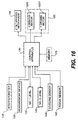
- FIG. 16 schematically shows the essential configuration of the control system of the projection exposure apparatus including the stage apparatus (110).
- This control system is configured with the control apparatus 130, consisting of a microcomputer (or minicomputer) including a CPU, ROM, RAM, I/O interface (none shown in the figure), etc., at its center, and the laser interferometer 126, measurement device 136, No. 1 level 138, No. 2 level 140, levelling sensor 144, focus sensor 142, etc., are connected to the input part of this control apparatus 130.
- the Z tilt drive mechanism 134, X driving motor 122X, and Y driving motor 122Y (in FIG. 14 represented as motor 122), etc., are connected to the output part of the control apparatus 130.
- the measurement beam (hereinafter referred to as interferometer laser ) IL is projected perpendicular to the moving mirror reflecting face, and it is assumed that the angle of inclination of the XY stage 116 with regard to the absolute level plane (standard plane) is nearly 0.
- interferometer laser the measurement beam
- the control device 130 since this position corresponds to the inclined protrusion at angle ⁇ on the wafer W surface, the control device 130, based on the output of the focus sensor 142 and levelling sensor 144 performs a focus and levelling adjustment, by controlling the Z tilt driving mechanism 134 so that the entire surface of the shot area of the wafer W surface is within the range of the focal depth of the projection optical system PL.
- the condition in which this focus and levelling adjustment has been performed is shown in FIG. 17(B).
- the XY stage 116 is inclined by the amount ⁇ with regard to the optical axis of the interference laser IL.
- the relative angle change ⁇ between the XY stage 116 and sample stage 118 is measured by the measurement device 136, and the angle of inclination ⁇ of the fixed base 114 itself with regard to the standard plane is measured by the No. 2 level 140, in addition the angle of inclination ( ⁇ + ⁇ ) of the XY stage 116 with regard to the standard plane is measured by the No. 1 level 138, and the measurement value of the measurement device 136, No. 1 level 138, and No. 2 level 140 are supplied to the control apparatus 130.
- the measurement value of the laser interferometer 126 is also supplied to the control apparatus 130.
- the CPU in the control apparatus 130 calculates the X direction error Err based upon formula (I) using the relative angle change ⁇ calculated in this way and the distance S obtained from the measurement values of the interferometer 126, and by correcting the measurement value of the interferometer 126 by this error amount, positions the XY stage 116, and hence the sample stage 118 accurately in the target position.
- control apparatus 130 positions the sample stand 118 in the target position by controlling the motor 122 while monitoring the measurement values of the laser interferometer 126, it corrects the measurement value of the laser interferometer 126 using the relative angle change ⁇ between the optical axis of the laser interferometer IL calculated in real time as described above and the reflecting face of the moving mirror 124.
- a computation device and correction device are realized by the function of the control apparatus 130 in this preferred embodiment, but, of course, these may be separate devices.
- the rotation ⁇ of the XY stage 116 around the Y axis (or X axis) caused by the flatness error of the guidance plane 114a is measured from the difference in the output of the No. 1 and No. 2 levels 138, 140, which are composed of electronic levels placed respectively on the XY stage 116 and guidance part 114a, and by subtracting the value ⁇ from the relative angle change ⁇ between the XY stage 116 and the sample stand 118 measured by means of a measurement device 136 mounted on the XY stage 116, the relative angle change ⁇ between the optical axis of the interferometer laser IL and the reflecting face of the moving mirror 124 can be obtained.
- the correction of the XY coordinate measurement error of the sample stand 118 produced can be performed with high level of accuracy by correcting the inclination of the sample stand 118 and matching the inclination of the wafer W and focal plane, and as a result the sample stand 118, and hence the wafer W thereon, can be positioned in the target position with high accuracy.
- the explanation referred to a case in which the relative angle change ⁇ between the optical axis of the interferometer laser IL and the reflecting face of the moving mirror 124 is obtained taking into consideration the inclination ⁇ of the fixed base 114 caused by fluctuations in the center of gravity of the apparatus accompanying the movement of the XY stage 116, but as stated previously, since devices having a certain degree of centering function are used as the antivibration pads 112, and in particular when an air type damper is used is an antivibration pad, the inclination ⁇ of the fixed base 114 can be made so small that it can be ignored, so that in this case the No. 2 level 140 is unnecessary.
- this is a device in which the rotation of the XY stage (116) around the Y (or X axis) caused by the flatness error in the guidance plane 114a, i.e., the relative angle change ⁇ between the optical axis of the interferometer laser IL and the XY stage 116, can be measured directly by means of the No. 1 level 138.
- the present invention is not limited to this, and the present invention may be applied in the same way to devices constituted so that the XY stage 116 moves along a vertical guidance plane provided on the fixed base 114.
- the stage apparatus in accordance with the present invention was used in a projection exposure apparatus, but the range of application of the present invention is not limited to this, and the present invention can also be used in devices in which the No. 2 stage (sample stand) can be inclined, and the No. 2 stage is positioned based upon the output of a lightwave interferometer such as a laser interferometer.
Landscapes
- Physics & Mathematics (AREA)
- General Physics & Mathematics (AREA)
- Exposure Of Semiconductors, Excluding Electron Or Ion Beam Exposure (AREA)
- Exposure And Positioning Against Photoresist Photosensitive Materials (AREA)
Applications Claiming Priority (6)
| Application Number | Priority Date | Filing Date | Title |
|---|---|---|---|
| JP8225474A JPH1070065A (ja) | 1996-08-27 | 1996-08-27 | 露光装置 |
| JP22547496 | 1996-08-27 | ||
| JP225474/96 | 1996-08-27 | ||
| JP247162/96 | 1996-08-29 | ||
| JP24716296 | 1996-08-29 | ||
| JP24716296A JPH1074687A (ja) | 1996-08-29 | 1996-08-29 | ステージ装置 |
Publications (2)
| Publication Number | Publication Date |
|---|---|
| EP0833208A2 true EP0833208A2 (fr) | 1998-04-01 |
| EP0833208A3 EP0833208A3 (fr) | 1999-11-24 |
Family
ID=26526660
Family Applications (1)
| Application Number | Title | Priority Date | Filing Date |
|---|---|---|---|
| EP97114842A Ceased EP0833208A3 (fr) | 1996-08-27 | 1997-08-27 | Dispositif porte-objet |
Country Status (3)
| Country | Link |
|---|---|
| US (1) | US6172373B1 (fr) |
| EP (1) | EP0833208A3 (fr) |
| KR (1) | KR19980019031A (fr) |
Cited By (10)
| Publication number | Priority date | Publication date | Assignee | Title |
|---|---|---|---|---|
| EP0848299A3 (fr) * | 1996-12-16 | 1999-12-01 | Nikon Corporation | Dispositif porte-objet et appareil de projection optique |
| EP0867776A3 (fr) * | 1997-03-26 | 2000-02-23 | Nikon Corporation | Méthode d'exposition, appareil d'exposition et méthode de fabrication d'un appareil d'exposition |
| US6411387B1 (en) | 1996-12-16 | 2002-06-25 | Nikon Corporation | Stage apparatus, projection optical apparatus and exposure method |
| EP1335248A1 (fr) * | 2002-02-12 | 2003-08-13 | ASML Netherlands B.V. | Appareil lithographique et méthode de fabrication d'un dispositif |
| EP1052683A4 (fr) * | 1998-01-29 | 2004-03-17 | Nikon Corp | Procede d'exposition et dispositif associe |
| EP0977244A3 (fr) * | 1998-07-29 | 2005-06-15 | Canon Kabushiki Kaisha | Système de support et procédé de commande du support pour l'utilisation dans un appareil d'exposition |
| US6992752B2 (en) | 2002-02-12 | 2006-01-31 | Asml Netherlands B.V. | Lithographic projection apparatus, computer program for control thereof, and device manufacturing method |
| WO2005109105A3 (fr) * | 2004-04-28 | 2006-06-22 | Litel Instr Inc | Appareil et procede de determination d'une courbure de champ a balayage dynamique |
| DE102006044285A1 (de) * | 2006-08-14 | 2008-02-21 | Physik Instrumente (Pi) Gmbh & Co. Kg | Verstelleinrichtung mit hoher Positionsauflösung, auch im Nano- oder Subnanometerbereich |
| CN103365115A (zh) * | 2012-03-30 | 2013-10-23 | 佳能株式会社 | 曝光装置、曝光装置的控制方法和器件制造方法 |
Families Citing this family (28)
| Publication number | Priority date | Publication date | Assignee | Title |
|---|---|---|---|---|
| JP2001075294A (ja) * | 1999-07-08 | 2001-03-23 | Nikon Corp | 面位置検出方法及び装置、並びに露光方法及び装置、露光装置の製造方法、半導体デバイス製造方法 |
| JP4337999B2 (ja) * | 1999-09-14 | 2009-09-30 | ソニー株式会社 | 焦点位置制御機構及び方法、並びに、半導体ウェハの検査装置及び方法 |
| JP2001082925A (ja) * | 1999-09-14 | 2001-03-30 | Sony Corp | 紫外光の焦点位置制御機構及び方法、並びに、検査装置及び方法 |
| US6381004B1 (en) * | 1999-09-29 | 2002-04-30 | Nikon Corporation | Exposure apparatus and device manufacturing method |
| US6538721B2 (en) * | 2000-03-24 | 2003-03-25 | Nikon Corporation | Scanning exposure apparatus |
| JP3863339B2 (ja) * | 2000-03-28 | 2006-12-27 | 株式会社東芝 | 光軸ずれ測定方法 |
| TW445567B (en) * | 2000-04-29 | 2001-07-11 | Promos Technologies Inc | Tray having positioning device |
| JP2001332595A (ja) * | 2000-05-25 | 2001-11-30 | Sony Corp | 焦点合わせ制御機構及びこれを用いた検査装置 |
| US20050136340A1 (en) * | 2000-07-21 | 2005-06-23 | Asml Netherlands B.V. | Lithographic apparatus and methods, patterning structure and method for making a patterning structure, device manufacturing method, and device manufactured thereby |
| EP1246014A1 (fr) * | 2001-03-30 | 2002-10-02 | ASML Netherlands B.V. | Appareil lithographique |
| US6504162B1 (en) * | 2000-09-15 | 2003-01-07 | Nikon Corporation | Stage device, control system, and method for stabilizing wafer stage and wafer table |
| US6537844B1 (en) | 2001-05-31 | 2003-03-25 | Kabushiki Kaisha Toshiba | Manufacturing method for exposure mask, generating method for mask substrate information, mask substrate, exposure mask, manufacturing method for semiconductor device and server |
| JP4362605B2 (ja) * | 2003-07-02 | 2009-11-11 | 大学共同利用機関法人情報・システム研究機構 | 顕微鏡装置 |
| KR20060078939A (ko) * | 2004-12-31 | 2006-07-05 | 안일신 | 수준기를 구비하는 타원해석기 |
| US7468589B2 (en) * | 2006-01-13 | 2008-12-23 | Asml Netherlands B.V. | Lithographic apparatus having a controlled motor, and motor control system and method |
| KR20060100307A (ko) * | 2006-08-08 | 2006-09-20 | 주식회사 거성기업 | 3차원 입체영상 재현용 전하결합소자 (3D imaging CCD) |
| WO2010137637A1 (fr) * | 2009-05-27 | 2010-12-02 | 株式会社ニコン | Dispositif de mesure de forme, procédé de mesure de forme, et procédé de production |
| JP6267550B2 (ja) * | 2014-03-12 | 2018-01-24 | キヤノン株式会社 | 測定装置および測定方法 |
| US10379048B2 (en) | 2015-06-26 | 2019-08-13 | Li-Cor, Inc. | Fluorescence biopsy specimen imager and methods |
| NL2017810A (en) * | 2015-12-15 | 2017-06-26 | Asml Netherlands Bv | Lithographic apparatus and device manufacturing method |
| EP3446098A1 (fr) | 2016-04-21 | 2019-02-27 | Li-Cor, Inc. | Imagerie 3d à modalités et axes multiples |
| US10278586B2 (en) | 2016-06-23 | 2019-05-07 | Li-Cor, Inc. | Complementary color flashing for multichannel image presentation |
| WO2018098162A1 (fr) | 2016-11-23 | 2018-05-31 | Li-Cor, Inc. | Procédé d'imagerie interactive adaptatif au mouvement |
| US10386301B2 (en) | 2017-04-25 | 2019-08-20 | Li-Cor, Inc. | Top-down and rotational side view biopsy specimen imager and methods |
| USD923325S1 (en) | 2019-03-05 | 2021-06-29 | Tom Downing | Pocket retaining device |
| USD890514S1 (en) | 2019-03-05 | 2020-07-21 | Tom Downing | Pocket retaining device |
| JP7406338B2 (ja) * | 2019-10-16 | 2023-12-27 | キヤノン株式会社 | ステージ装置、ステージ装置の調整方法、および物品製造方法 |
| CN116202413A (zh) * | 2023-02-16 | 2023-06-02 | 中国航空工业集团公司北京航空精密机械研究所 | 一种用于发动机回转体的向导式调心调倾辅助方法及系统 |
Family Cites Families (21)
| Publication number | Priority date | Publication date | Assignee | Title |
|---|---|---|---|---|
| FR2330030A1 (fr) | 1975-10-31 | 1977-05-27 | Thomson Csf | Nouvel appareil photorepeteur de masques de haute precision |
| US4383757A (en) | 1979-04-02 | 1983-05-17 | Optimetrix Corporation | Optical focusing system |
| JPS58103136A (ja) | 1981-12-16 | 1983-06-20 | Nippon Kogaku Kk <Nikon> | 基板の傾き設定装置 |
| JPS58113706A (ja) | 1981-12-26 | 1983-07-06 | Nippon Kogaku Kk <Nikon> | 水平位置検出装置 |
| JPS61287229A (ja) * | 1985-06-14 | 1986-12-17 | Nippon Kogaku Kk <Nikon> | 露光装置、及び該露光装置を用いた回路パターン製造方法 |
| JPS6316418A (ja) | 1986-07-08 | 1988-01-23 | Hitachi Chem Co Ltd | 磁気デイスク基板 |
| JP2704734B2 (ja) * | 1988-09-05 | 1998-01-26 | キヤノン株式会社 | ステージ位置決め補正方法及び装置 |
| JP2679186B2 (ja) * | 1988-12-05 | 1997-11-19 | 株式会社ニコン | 露光装置 |
| US5151749A (en) * | 1989-06-08 | 1992-09-29 | Nikon Corporation | Method of and apparatus for measuring coordinate position and positioning an object |
| US4978841A (en) * | 1989-08-24 | 1990-12-18 | Lasa Industries, Inc. | Automatic leveling system and a method of leveling a workpiece based on focus detection |
| JP3218478B2 (ja) * | 1992-09-04 | 2001-10-15 | 株式会社ニコン | 投影露光装置及び方法 |
| US5424552A (en) | 1991-07-09 | 1995-06-13 | Nikon Corporation | Projection exposing apparatus |
| JP3381313B2 (ja) * | 1992-07-28 | 2003-02-24 | 株式会社ニコン | 露光装置および露光方法並びに素子製造方法 |
| KR100300618B1 (ko) | 1992-12-25 | 2001-11-22 | 오노 시게오 | 노광방법,노광장치,및그장치를사용하는디바이스제조방법 |
| JP3316833B2 (ja) * | 1993-03-26 | 2002-08-19 | 株式会社ニコン | 走査露光方法、面位置設定装置、走査型露光装置、及び前記方法を使用するデバイス製造方法 |
| US5461237A (en) * | 1993-03-26 | 1995-10-24 | Nikon Corporation | Surface-position setting apparatus |
| US5654553A (en) | 1993-06-10 | 1997-08-05 | Nikon Corporation | Projection exposure apparatus having an alignment sensor for aligning a mask image with a substrate |
| US5635722A (en) | 1993-07-01 | 1997-06-03 | Nikon Corporation | Projection exposure method and apparatus capable of performing focus detection with high accuracy |
| JP3308063B2 (ja) | 1993-09-21 | 2002-07-29 | 株式会社ニコン | 投影露光方法及び装置 |
| US5783833A (en) | 1994-12-12 | 1998-07-21 | Nikon Corporation | Method and apparatus for alignment with a substrate, using coma imparting optics |
| US5825043A (en) | 1996-10-07 | 1998-10-20 | Nikon Precision Inc. | Focusing and tilting adjustment system for lithography aligner, manufacturing apparatus or inspection apparatus |
-
1997
- 1997-08-26 KR KR1019970041270A patent/KR19980019031A/ko not_active Ceased
- 1997-08-27 EP EP97114842A patent/EP0833208A3/fr not_active Ceased
-
1999
- 1999-10-18 US US09/419,771 patent/US6172373B1/en not_active Expired - Fee Related
Cited By (13)
| Publication number | Priority date | Publication date | Assignee | Title |
|---|---|---|---|---|
| US6411387B1 (en) | 1996-12-16 | 2002-06-25 | Nikon Corporation | Stage apparatus, projection optical apparatus and exposure method |
| EP0848299A3 (fr) * | 1996-12-16 | 1999-12-01 | Nikon Corporation | Dispositif porte-objet et appareil de projection optique |
| EP0867776A3 (fr) * | 1997-03-26 | 2000-02-23 | Nikon Corporation | Méthode d'exposition, appareil d'exposition et méthode de fabrication d'un appareil d'exposition |
| EP1052683A4 (fr) * | 1998-01-29 | 2004-03-17 | Nikon Corp | Procede d'exposition et dispositif associe |
| EP0977244A3 (fr) * | 1998-07-29 | 2005-06-15 | Canon Kabushiki Kaisha | Système de support et procédé de commande du support pour l'utilisation dans un appareil d'exposition |
| US6992752B2 (en) | 2002-02-12 | 2006-01-31 | Asml Netherlands B.V. | Lithographic projection apparatus, computer program for control thereof, and device manufacturing method |
| EP1335248A1 (fr) * | 2002-02-12 | 2003-08-13 | ASML Netherlands B.V. | Appareil lithographique et méthode de fabrication d'un dispositif |
| WO2005109105A3 (fr) * | 2004-04-28 | 2006-06-22 | Litel Instr Inc | Appareil et procede de determination d'une courbure de champ a balayage dynamique |
| US7126668B2 (en) | 2004-04-28 | 2006-10-24 | Litel Instruments | Apparatus and process for determination of dynamic scan field curvature |
| DE102006044285A1 (de) * | 2006-08-14 | 2008-02-21 | Physik Instrumente (Pi) Gmbh & Co. Kg | Verstelleinrichtung mit hoher Positionsauflösung, auch im Nano- oder Subnanometerbereich |
| CN103365115A (zh) * | 2012-03-30 | 2013-10-23 | 佳能株式会社 | 曝光装置、曝光装置的控制方法和器件制造方法 |
| US9097991B2 (en) | 2012-03-30 | 2015-08-04 | Canon Kabushiki Kaisha | Exposure apparatus, method of controlling the same and method of manufacturing device |
| CN103365115B (zh) * | 2012-03-30 | 2016-01-27 | 佳能株式会社 | 曝光装置、曝光装置的控制方法和器件制造方法 |
Also Published As
| Publication number | Publication date |
|---|---|
| EP0833208A3 (fr) | 1999-11-24 |
| KR19980019031A (ko) | 1998-06-05 |
| US6172373B1 (en) | 2001-01-09 |
Similar Documents
| Publication | Publication Date | Title |
|---|---|---|
| US6172373B1 (en) | Stage apparatus with improved positioning capability | |
| JP2679186B2 (ja) | 露光装置 | |
| US6287734B2 (en) | Exposure method | |
| JP3401769B2 (ja) | 露光方法、ステージ装置、及び露光装置 | |
| JP4878831B2 (ja) | リソグラフィ装置及びデバイス製造方法 | |
| KR19980042558A (ko) | 투영 노광 장치 및 투영 노광 방법 | |
| TW201843537A (zh) | 曝光裝置、曝光方法、以及元件製造方法 | |
| US5737063A (en) | Projection exposure apparatus | |
| JP2004014876A (ja) | 調整方法、空間像計測方法及び像面計測方法、並びに露光装置 | |
| USH1774H (en) | Projecting exposure apparatus and method of exposing a circuit substrate | |
| JP4650619B2 (ja) | 駆動ユニット、光学ユニット、光学装置、並びに露光装置 | |
| US20090244505A1 (en) | Positioning unit of optical element, optical system, exposure apparatus, adjustment method of optical system | |
| US20070064212A1 (en) | Projection exposure apparatus and stage unit, and exposure method | |
| JP2004140290A (ja) | ステージ装置 | |
| JPH10294257A (ja) | 基板の面位置制御方法及び制御装置、並びに露光方法及び露光装置 | |
| JPH11186129A (ja) | 走査型露光方法及び装置 | |
| JP3520881B2 (ja) | 露光装置 | |
| JPH1070065A (ja) | 露光装置 | |
| JP4254356B2 (ja) | ステージ装置、露光装置、及びデバイス製造方法 | |
| US7894140B2 (en) | Compensation techniques for fluid and magnetic bearings | |
| JPH1074687A (ja) | ステージ装置 | |
| KR20040022401A (ko) | 다수의 간섭계 빔을 사용하는 레티클 초점 측정 시스템 및방법 | |
| JPH11168050A (ja) | 露光方法及び装置 | |
| JPH10261567A (ja) | 投影露光装置及び投影光学系の光学特性測定方法 | |
| JPH11340125A (ja) | 露光方法及び装置 |
Legal Events
| Date | Code | Title | Description |
|---|---|---|---|
| PUAI | Public reference made under article 153(3) epc to a published international application that has entered the european phase |
Free format text: ORIGINAL CODE: 0009012 |
|
| AK | Designated contracting states |
Kind code of ref document: A2 Designated state(s): NL |
|
| PUAL | Search report despatched |
Free format text: ORIGINAL CODE: 0009013 |
|
| AK | Designated contracting states |
Kind code of ref document: A3 Designated state(s): AT BE CH DE DK ES FI FR GB GR IE IT LI LU MC NL PT SE |
|
| 17P | Request for examination filed |
Effective date: 20000321 |
|
| AKX | Designation fees paid |
Free format text: NL |
|
| 17Q | First examination report despatched |
Effective date: 20000628 |
|
| REG | Reference to a national code |
Ref country code: DE Ref legal event code: 8566 |
|
| GRAG | Despatch of communication of intention to grant |
Free format text: ORIGINAL CODE: EPIDOS AGRA |
|
| STAA | Information on the status of an ep patent application or granted ep patent |
Free format text: STATUS: THE APPLICATION HAS BEEN REFUSED |
|
| 18R | Application refused |
Effective date: 20011201 |