EP0833414A2 - Elektrischer Verbinder mit einem Kurzschlusskontakt und Kurzschlusskontakt - Google Patents
Elektrischer Verbinder mit einem Kurzschlusskontakt und Kurzschlusskontakt Download PDFInfo
- Publication number
- EP0833414A2 EP0833414A2 EP97116155A EP97116155A EP0833414A2 EP 0833414 A2 EP0833414 A2 EP 0833414A2 EP 97116155 A EP97116155 A EP 97116155A EP 97116155 A EP97116155 A EP 97116155A EP 0833414 A2 EP0833414 A2 EP 0833414A2
- Authority
- EP
- European Patent Office
- Prior art keywords
- short
- circuit contact
- contacts
- circuit
- area
- Prior art date
- Legal status (The legal status is an assumption and is not a legal conclusion. Google has not performed a legal analysis and makes no representation as to the accuracy of the status listed.)
- Withdrawn
Links
Images

Classifications
-
- H—ELECTRICITY
- H01—ELECTRIC ELEMENTS
- H01R—ELECTRICALLY-CONDUCTIVE CONNECTIONS; STRUCTURAL ASSOCIATIONS OF A PLURALITY OF MUTUALLY-INSULATED ELECTRICAL CONNECTING ELEMENTS; COUPLING DEVICES; CURRENT COLLECTORS
- H01R31/00—Coupling parts supported only by co-operation with counterpart
- H01R31/08—Short-circuiting members for bridging contacts in a counterpart
- H01R31/085—Short circuiting bus-strips
Definitions
- the invention relates to an electrical connector with the following features: It is an insulating housing provided with a variety of electrical contacts that Contacts are in a transition area from the insulating one Surround the housing, there is at least one short-circuit contact arranged such that two contacts with one Short-circuit area of the short-circuit contact short-circuited will.
- the invention further relates to a Short circuit contact.
- Permanent short-circuit contacts that cannot be detached, are known, for example from US 4,628,818.
- a metal plate On one side of a connector housing is in the range of two contacts arranged next to each other, for example round contact pins, a metal plate, arranged perpendicular to the direction of insertion.
- the metal plate indicates for each contact that has to be short-circuited, a recess.
- the shape and size of the recess are designed so that the metal plate clamps on the Contacts can be attached.
- the plate points to this Edge of the recess serrations, claws or as barbs curved metal surfaces.
- the diameter of the recess is therefore smaller in some areas than the diameter of the Contact.
- an electrical Connector with the following characteristics: It is an insulating one Housing with a large number of electrical contacts intended; the contacts are in a transition area from insulated housing; at least one Short-circuit contact is arranged such that two each Contacts with a short circuit area of the Short-circuit contact are short-circuited; of the Short-circuit contact has at least one insertion area which has at least one fastening element, such that the short circuit contact in a wall of the Housing is held, as well as by a Short circuit contact with the features of the claim 8th.
- the short-circuit contact is simply in the Housing can be mounted. This is achieved that the short circuit contact in the wall of the housing is insertable and that the short-circuit contact at least has a shoulder on which pressure can be applied, to insert the short circuit contact into the wall.
- the short circuit contact from the outside of the housing is not visible. This will achieved in that the short-circuit contact on a Mounting side of the wall of the housing is arranged.
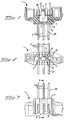
- FIG 1 is a section through an electrical Connector shown.
- the connector consists of a insulating housing 1 in which six contacts 2 in two Rows of three contacts 2 are arranged. The cut was along the midline between the two rows made of electrical contacts 2.
- the isolating Housing 1 has a wall 8 with a mounting side 9 and a plug side 11.
- the contacts 2 are in the Transitional area 3 surrounded by the insulating housing 1.
- the electrical connector can be made in an overmolding process are produced, that is, the contacts 2 are from Plastic molded around the wall 8 in the transition area 3. In Another type of manufacture, the contacts 2 in the Pierced wall 8.
- the Short circuit contact 4 is arranged such that two contacts from two adjacent rows with a short-circuit area 5 of the short-circuit contact 4 be short-circuited.
- FIG 2 is a view on the mounting side 9 of the insulating housing 1 shown.
- the short circuit area 5 of the short-circuit contact 4 is on the mounting side 9 of the Wall 8 of the housing 1 arranged.
- Figure 2 is also can be seen how the transition region 3 of the contacts 2 in insulating housing 1 is arranged.
- Figure 3 is a side view of the insulating housing 1 shown. Here you can see how the contacts 2 through the housing 1 from the mounting side 9 to Mating side 11 run. Of contacts 2 is the Mating area 20 and the connecting area 21 can be seen.
- FIG. 4 shows a section through the insulating housing 1 shown along the line BB of Figure 3. Here is can be seen how the contacts 2 in the insulating housing 1st are arranged.
- the short-circuit contact is 4 in FIGS. 5a and 5b shown enlarged in two side views.
- the short-circuit contact 4 has an insertion area 6 and a short-circuit area 5.
- the short circuit area 5 is curved in a ring.
- the insertion area 6 has two Fasteners 7 on and two shoulders 10. With the Fastening element 7, the short-circuit contact 4 is fixed in the insulating housing 1 held. By pressing the Shoulders 10 is the insertion area 6 in the wall 8 of the insulating housing 1 inserted.
- the short circuit contact 4 contacted with the circularly curved Short circuit area 5 two opposite each other Contacts 2.
- the short-circuit contact 4 is not on one of the electrical contacts 2, but on the wall 8 of the insulating housing 1 attached. Therefore this can Short-circuit contact 4 advantageous for electrical Connectors with sensitive contacts 2, e.g. with gold or silver coated contacts 2 can be used.
- the electrical contacts remain 2 also short-circuited if, e.g. through strong Vibrations or other forces, the contacts 2, which are arranged in two opposite rows be moved apart or bent.
- the electrical described in this embodiment Connector is used, for example, to Winding wires of an electric motor with a plug too connect.
- the winding wires are at the connection area 21 of the electrical connector connected and the plug is plugged into the plug area 20 of the contacts 2.
- Of the electrical connector is easy to manufacture if both the contacts 2, as well as the short-circuit contact 4 on the same production line.
Landscapes
- Coupling Device And Connection With Printed Circuit (AREA)
- Connections By Means Of Piercing Elements, Nuts, Or Screws (AREA)
Abstract
Description
Claims (11)
- Elektrischer Verbinder mit folgenden Merkmalen:a) es ist ein isolierendes Gehäuse (1) mit einer Vielzahl elektrischer Kontakte (2) vorgesehen,b) die Kontakte (2) sind in einem Übergangsbereich (3) vom isolierenden Gehäuse (1) umgeben,c) mindestens ein Kurzschlusskontakt (4) ist derart angeordnet, dass jeweils zwei Kontakte (2) mit einem Kurzschlussbereich (5) des Kurzschlusskontaktes (4) kurzgeschlossen werden,
dadurch gekennzeichnet,
dass der Kurzschlusskontakt (4) zumindest einen Einsteckbereich (6) aufweist, der mindestens ein Befestigungselement (7) aufweist, derart, dass der Kurzschlusskontakt (4) in einer Wand (8) des Gehäuses (1) festgehalten ist. - Elektrischer Verbinder nach Anspruch 1, dadurch gekennzeichnet, dass der Kurzschlusskontakt (4) jeweils zwei Kontakte (2) in zwei nebeneinander liegenden Reihen kontaktiert.
- Elektrischer Verbinder nach Anspruch 1 oder 2, dadurch gekennzeichnet, dass der Kurzschlussbereich (5) des Kurzschlusskontaktes (4) derart geformt ist, dass der Kurzschlusskontakt (4) jeweils zwei Kontakte (2) federnd kontaktiert.
- Elektrischer Verbinder nach einem der Ansprüche 1 bis 3, dadurch gekennzeichnet, dass der Kurzschlussbereich (5) des Kurzschlusskontaktes (4) auf einer Montageseite (9) der Wand (8) des Gehäuses (1) angeordnet ist.
- Elektrischer Verbinder nach einem der Ansprüche 1 bis 4, dadurch gekennzeichnet, dass der Kurzschlusskontakt (4) am Einsteckbereich (6) zumindest eine Schulter (10) aufweist, die frei zugänglich ist und das Einstecken in die Wand (8) erleichtert.
- Elektrischer Verbinder nach einem der Ansprüche 1 bis 5, dadurch gekennzeichnet, dass der Kurzschlussbereich (5) des Kurzschlusskontaktes (4) ringförmig gebogen ist.
- Elektrischer Verbinder nach einem der Ansprüche 1 bis 6, dadurch gekennzeichnet, dass der Kurzschlusskontakt (4) durch Stanzen und Biegen aus einem Metallblechteil hergestellt ist.
- Kurzschlusskontakt (4) mit einem Kurzschlussbereich (5) zum Kurzschliessen zweier Kontakte und einem Einsteckbereich (6) zum Befestigen des Kurzschlusskontaktes in einem Gehäuse, wobei der Einsteckbereich (6) mindestens ein Befestigungselement (7) aufweist, derart, dass der Kurzschlusskontakt (4) in einer Wand (8) des Gehäuses (1) festgehalten ist.
- Kurzschlusskontakt nach Anspruch 8, dadurch gekennzeichnet, dass der Kurzschlussbereich (5) des Kurzschlusskontaktes (4) gebogen ist.
- Kurzschlusskontakt nach einem der Ansprüche 8 oder 9, dadurch gekennzeichnet, dass am Einsteckbereich (6) zumindest eine Schulter (10) vorgesehen ist, die frei zugänglich ist, und auf die ein Druck ausgeübt werden kann, um das Einstecken in eine Wand zu erleichtern.
- Kurzschlusskontakt nach einem der Ansprüche 8 bis 10, dadurch gekennzeichnet, dass der Kurzschlusskontakt (4) durch stanzen und biegen aus einem Metallblech hergestellt ist.
Applications Claiming Priority (2)
| Application Number | Priority Date | Filing Date | Title |
|---|---|---|---|
| DE1996139723 DE19639723A1 (de) | 1996-09-26 | 1996-09-26 | Elektrischer Verbinder mit einem Kurzschlußkontakt und Kurzschlußkontakt |
| DE19639723 | 1996-09-26 |
Publications (2)
| Publication Number | Publication Date |
|---|---|
| EP0833414A2 true EP0833414A2 (de) | 1998-04-01 |
| EP0833414A3 EP0833414A3 (de) | 1999-01-13 |
Family
ID=7807063
Family Applications (1)
| Application Number | Title | Priority Date | Filing Date |
|---|---|---|---|
| EP97116155A Withdrawn EP0833414A3 (de) | 1996-09-26 | 1997-09-17 | Elektrischer Verbinder mit einem Kurzschlusskontakt und Kurzschlusskontakt |
Country Status (3)
| Country | Link |
|---|---|
| EP (1) | EP0833414A3 (de) |
| JP (1) | JPH10125424A (de) |
| DE (1) | DE19639723A1 (de) |
Cited By (1)
| Publication number | Priority date | Publication date | Assignee | Title |
|---|---|---|---|---|
| CN105375155A (zh) * | 2015-12-11 | 2016-03-02 | 中国电子科技集团公司第四十一研究所 | 一种同轴探头短路机构及其操作方法 |
Families Citing this family (2)
| Publication number | Priority date | Publication date | Assignee | Title |
|---|---|---|---|---|
| EP1603216B1 (de) * | 2004-05-26 | 2011-11-09 | Johnson Electric Switzerland AG | Bürstenloser Elektromotor und Verfahren zur Herstellung desselben |
| JP5738093B2 (ja) * | 2011-06-30 | 2015-06-17 | 矢崎総業株式会社 | ジョイントコネクタ |
Family Cites Families (9)
| Publication number | Priority date | Publication date | Assignee | Title |
|---|---|---|---|---|
| NL88692C (de) * | 1953-10-31 | |||
| US4392702A (en) * | 1981-04-02 | 1983-07-12 | Ark-Les Corporation | Shorting jumper |
| DE3338929A1 (de) * | 1983-10-27 | 1985-05-09 | Bayern-Chemie Gesellschaft für flugchemische Antriebe mbH, 8261 Aschau | Kurzschlussfeder |
| US5266043A (en) * | 1992-01-31 | 1993-11-30 | Augat Inc. | Fully programmable connector |
| JP2903918B2 (ja) * | 1992-12-09 | 1999-06-14 | 住友電装株式会社 | ジョイントコネクタ |
| JP2725752B2 (ja) * | 1992-12-14 | 1998-03-11 | 矢崎総業株式会社 | コネクタ |
| US5273448A (en) * | 1993-03-16 | 1993-12-28 | The Whitaker Corporation | Shorting spring concept |
| US5449301A (en) * | 1993-11-17 | 1995-09-12 | Berg Technology, Inc. | Shunt connector |
| US5558530A (en) * | 1994-07-05 | 1996-09-24 | General Motors Corporation | Electrical connector assembly having a terminal locking bussing plate |
-
1996
- 1996-09-26 DE DE1996139723 patent/DE19639723A1/de not_active Ceased
-
1997
- 1997-09-12 JP JP26817297A patent/JPH10125424A/ja active Pending
- 1997-09-17 EP EP97116155A patent/EP0833414A3/de not_active Withdrawn
Cited By (1)
| Publication number | Priority date | Publication date | Assignee | Title |
|---|---|---|---|---|
| CN105375155A (zh) * | 2015-12-11 | 2016-03-02 | 中国电子科技集团公司第四十一研究所 | 一种同轴探头短路机构及其操作方法 |
Also Published As
| Publication number | Publication date |
|---|---|
| JPH10125424A (ja) | 1998-05-15 |
| DE19639723A1 (de) | 1998-04-09 |
| EP0833414A3 (de) | 1999-01-13 |
Similar Documents
| Publication | Publication Date | Title |
|---|---|---|
| DE69422479T2 (de) | Elektrischer Schneidklemmverbinder mit verbesserter Zugentlastung | |
| DE69300865T2 (de) | Elektrischer verbinder mit blech als steckkontaktmaterial. | |
| DE69915732T2 (de) | Schneidklemmbuchsenkontakt mit hoher Haltekraft | |
| DE102010029205A1 (de) | Draht/Platte-Verbinder | |
| EP1189307A3 (de) | Elektrische Reihenklemme | |
| DE9103278U1 (de) | Elektrischer Zwitteranschluß | |
| DE102010031588A1 (de) | Draht/Platte-Verbinder | |
| DE3889841T2 (de) | Isolierungsverstellanordnung. | |
| EP3782238B1 (de) | System von geschirmten steckverbindermodulen für modulare industriesteckverbinder | |
| EP0211357B1 (de) | Verfahren zur Herstellung einer Kontakteinrichtung auf einer Leiterplatte | |
| DE102017125505A1 (de) | Steckerbuchse für Leiterplatinen | |
| EP1128476B1 (de) | Steckverbinder sowie Verfahren zur Herstellung eines Steckverbinders | |
| DE20003951U1 (de) | Mehrpoliger elektrischer Steckverbinder | |
| EP2887461A1 (de) | Einpoliger elektrischer Verbinder mit hermaphroditischen Kontaktelementen | |
| EP0833414A2 (de) | Elektrischer Verbinder mit einem Kurzschlusskontakt und Kurzschlusskontakt | |
| DE9415087U1 (de) | Steckbare elektrische Verbindungsvorrichtung | |
| DE102016209604A1 (de) | Einpress-Anschluss, Halbleitervorrichtung, Leistungswandlungsvorrichtung und Verfahren zur Herstellung eines Einpress-Anschlusses | |
| DE102019132127A1 (de) | Buchsenkontakt mit seitlichem Kabelabgang | |
| EP0405337A2 (de) | Schutzstecker für eine Verteilerleiste in einer Telekommunikationsanlage | |
| DE10061112A1 (de) | Steckverbindung für elektrische Bauelemente | |
| DE112012001119T5 (de) | Verbinder | |
| DE19830878A1 (de) | Elektrisches Bauteil | |
| DE19937313C1 (de) | Messerkontakt | |
| DE19625847A1 (de) | Elektrischer Buchsenanschluß | |
| DE102012011047B4 (de) | Verbindungsbauteil und Schaltungsanordnung mit dem Verbindungsbauteil |
Legal Events
| Date | Code | Title | Description |
|---|---|---|---|
| PUAI | Public reference made under article 153(3) epc to a published international application that has entered the european phase |
Free format text: ORIGINAL CODE: 0009012 |
|
| AK | Designated contracting states |
Kind code of ref document: A2 Designated state(s): AT BE CH DE DK ES FI FR GB GR IE IT LI LU MC NL PT SE |
|
| AX | Request for extension of the european patent |
Free format text: AL;LT;LV;RO;SI |
|
| PUAL | Search report despatched |
Free format text: ORIGINAL CODE: 0009013 |
|
| AK | Designated contracting states |
Kind code of ref document: A3 Designated state(s): AT BE CH DE DK ES FI FR GB GR IE IT LI LU MC NL PT SE |
|
| AX | Request for extension of the european patent |
Free format text: AL;LT;LV;RO;SI |
|
| AKX | Designation fees paid | ||
| STAA | Information on the status of an ep patent application or granted ep patent |
Free format text: STATUS: THE APPLICATION IS DEEMED TO BE WITHDRAWN |
|
| 18D | Application deemed to be withdrawn |
Effective date: 19990714 |
|
| REG | Reference to a national code |
Ref country code: DE Ref legal event code: 8566 |