EP0833414A2 - Connecteur électrique ayant une contact de court circuit et un tel contact de court circuit - Google Patents
Connecteur électrique ayant une contact de court circuit et un tel contact de court circuit Download PDFInfo
- Publication number
- EP0833414A2 EP0833414A2 EP97116155A EP97116155A EP0833414A2 EP 0833414 A2 EP0833414 A2 EP 0833414A2 EP 97116155 A EP97116155 A EP 97116155A EP 97116155 A EP97116155 A EP 97116155A EP 0833414 A2 EP0833414 A2 EP 0833414A2
- Authority
- EP
- European Patent Office
- Prior art keywords
- short
- circuit contact
- contacts
- circuit
- area
- Prior art date
- Legal status (The legal status is an assumption and is not a legal conclusion. Google has not performed a legal analysis and makes no representation as to the accuracy of the status listed.)
- Withdrawn
Links
Images

Classifications
-
- H—ELECTRICITY
- H01—ELECTRIC ELEMENTS
- H01R—ELECTRICALLY-CONDUCTIVE CONNECTIONS; STRUCTURAL ASSOCIATIONS OF A PLURALITY OF MUTUALLY-INSULATED ELECTRICAL CONNECTING ELEMENTS; COUPLING DEVICES; CURRENT COLLECTORS
- H01R31/00—Coupling parts supported only by co-operation with counterpart
- H01R31/08—Short-circuiting members for bridging contacts in a counterpart
- H01R31/085—Short circuiting bus-strips
Definitions
- the invention relates to an electrical connector with the following features: It is an insulating housing provided with a variety of electrical contacts that Contacts are in a transition area from the insulating one Surround the housing, there is at least one short-circuit contact arranged such that two contacts with one Short-circuit area of the short-circuit contact short-circuited will.
- the invention further relates to a Short circuit contact.
- Permanent short-circuit contacts that cannot be detached, are known, for example from US 4,628,818.
- a metal plate On one side of a connector housing is in the range of two contacts arranged next to each other, for example round contact pins, a metal plate, arranged perpendicular to the direction of insertion.
- the metal plate indicates for each contact that has to be short-circuited, a recess.
- the shape and size of the recess are designed so that the metal plate clamps on the Contacts can be attached.
- the plate points to this Edge of the recess serrations, claws or as barbs curved metal surfaces.
- the diameter of the recess is therefore smaller in some areas than the diameter of the Contact.
- an electrical Connector with the following characteristics: It is an insulating one Housing with a large number of electrical contacts intended; the contacts are in a transition area from insulated housing; at least one Short-circuit contact is arranged such that two each Contacts with a short circuit area of the Short-circuit contact are short-circuited; of the Short-circuit contact has at least one insertion area which has at least one fastening element, such that the short circuit contact in a wall of the Housing is held, as well as by a Short circuit contact with the features of the claim 8th.
- the short-circuit contact is simply in the Housing can be mounted. This is achieved that the short circuit contact in the wall of the housing is insertable and that the short-circuit contact at least has a shoulder on which pressure can be applied, to insert the short circuit contact into the wall.
- the short circuit contact from the outside of the housing is not visible. This will achieved in that the short-circuit contact on a Mounting side of the wall of the housing is arranged.
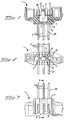
- FIG 1 is a section through an electrical Connector shown.
- the connector consists of a insulating housing 1 in which six contacts 2 in two Rows of three contacts 2 are arranged. The cut was along the midline between the two rows made of electrical contacts 2.
- the isolating Housing 1 has a wall 8 with a mounting side 9 and a plug side 11.
- the contacts 2 are in the Transitional area 3 surrounded by the insulating housing 1.
- the electrical connector can be made in an overmolding process are produced, that is, the contacts 2 are from Plastic molded around the wall 8 in the transition area 3. In Another type of manufacture, the contacts 2 in the Pierced wall 8.
- the Short circuit contact 4 is arranged such that two contacts from two adjacent rows with a short-circuit area 5 of the short-circuit contact 4 be short-circuited.
- FIG 2 is a view on the mounting side 9 of the insulating housing 1 shown.
- the short circuit area 5 of the short-circuit contact 4 is on the mounting side 9 of the Wall 8 of the housing 1 arranged.
- Figure 2 is also can be seen how the transition region 3 of the contacts 2 in insulating housing 1 is arranged.
- Figure 3 is a side view of the insulating housing 1 shown. Here you can see how the contacts 2 through the housing 1 from the mounting side 9 to Mating side 11 run. Of contacts 2 is the Mating area 20 and the connecting area 21 can be seen.
- FIG. 4 shows a section through the insulating housing 1 shown along the line BB of Figure 3. Here is can be seen how the contacts 2 in the insulating housing 1st are arranged.
- the short-circuit contact is 4 in FIGS. 5a and 5b shown enlarged in two side views.
- the short-circuit contact 4 has an insertion area 6 and a short-circuit area 5.
- the short circuit area 5 is curved in a ring.
- the insertion area 6 has two Fasteners 7 on and two shoulders 10. With the Fastening element 7, the short-circuit contact 4 is fixed in the insulating housing 1 held. By pressing the Shoulders 10 is the insertion area 6 in the wall 8 of the insulating housing 1 inserted.
- the short circuit contact 4 contacted with the circularly curved Short circuit area 5 two opposite each other Contacts 2.
- the short-circuit contact 4 is not on one of the electrical contacts 2, but on the wall 8 of the insulating housing 1 attached. Therefore this can Short-circuit contact 4 advantageous for electrical Connectors with sensitive contacts 2, e.g. with gold or silver coated contacts 2 can be used.
- the electrical contacts remain 2 also short-circuited if, e.g. through strong Vibrations or other forces, the contacts 2, which are arranged in two opposite rows be moved apart or bent.
- the electrical described in this embodiment Connector is used, for example, to Winding wires of an electric motor with a plug too connect.
- the winding wires are at the connection area 21 of the electrical connector connected and the plug is plugged into the plug area 20 of the contacts 2.
- Of the electrical connector is easy to manufacture if both the contacts 2, as well as the short-circuit contact 4 on the same production line.
Landscapes
- Coupling Device And Connection With Printed Circuit (AREA)
- Connections By Means Of Piercing Elements, Nuts, Or Screws (AREA)
Applications Claiming Priority (2)
| Application Number | Priority Date | Filing Date | Title |
|---|---|---|---|
| DE1996139723 DE19639723A1 (de) | 1996-09-26 | 1996-09-26 | Elektrischer Verbinder mit einem Kurzschlußkontakt und Kurzschlußkontakt |
| DE19639723 | 1996-09-26 |
Publications (2)
| Publication Number | Publication Date |
|---|---|
| EP0833414A2 true EP0833414A2 (fr) | 1998-04-01 |
| EP0833414A3 EP0833414A3 (fr) | 1999-01-13 |
Family
ID=7807063
Family Applications (1)
| Application Number | Title | Priority Date | Filing Date |
|---|---|---|---|
| EP97116155A Withdrawn EP0833414A3 (fr) | 1996-09-26 | 1997-09-17 | Connecteur électrique ayant une contact de court circuit et un tel contact de court circuit |
Country Status (3)
| Country | Link |
|---|---|
| EP (1) | EP0833414A3 (fr) |
| JP (1) | JPH10125424A (fr) |
| DE (1) | DE19639723A1 (fr) |
Cited By (1)
| Publication number | Priority date | Publication date | Assignee | Title |
|---|---|---|---|---|
| CN105375155A (zh) * | 2015-12-11 | 2016-03-02 | 中国电子科技集团公司第四十一研究所 | 一种同轴探头短路机构及其操作方法 |
Families Citing this family (2)
| Publication number | Priority date | Publication date | Assignee | Title |
|---|---|---|---|---|
| EP1603216B1 (fr) * | 2004-05-26 | 2011-11-09 | Johnson Electric Switzerland AG | Moteur électrique sans balais et méthode pour sa fabrication |
| JP5738093B2 (ja) * | 2011-06-30 | 2015-06-17 | 矢崎総業株式会社 | ジョイントコネクタ |
Family Cites Families (9)
| Publication number | Priority date | Publication date | Assignee | Title |
|---|---|---|---|---|
| NL88692C (fr) * | 1953-10-31 | |||
| US4392702A (en) * | 1981-04-02 | 1983-07-12 | Ark-Les Corporation | Shorting jumper |
| DE3338929A1 (de) * | 1983-10-27 | 1985-05-09 | Bayern-Chemie Gesellschaft für flugchemische Antriebe mbH, 8261 Aschau | Kurzschlussfeder |
| US5266043A (en) * | 1992-01-31 | 1993-11-30 | Augat Inc. | Fully programmable connector |
| JP2903918B2 (ja) * | 1992-12-09 | 1999-06-14 | 住友電装株式会社 | ジョイントコネクタ |
| JP2725752B2 (ja) * | 1992-12-14 | 1998-03-11 | 矢崎総業株式会社 | コネクタ |
| US5273448A (en) * | 1993-03-16 | 1993-12-28 | The Whitaker Corporation | Shorting spring concept |
| US5449301A (en) * | 1993-11-17 | 1995-09-12 | Berg Technology, Inc. | Shunt connector |
| US5558530A (en) * | 1994-07-05 | 1996-09-24 | General Motors Corporation | Electrical connector assembly having a terminal locking bussing plate |
-
1996
- 1996-09-26 DE DE1996139723 patent/DE19639723A1/de not_active Ceased
-
1997
- 1997-09-12 JP JP26817297A patent/JPH10125424A/ja active Pending
- 1997-09-17 EP EP97116155A patent/EP0833414A3/fr not_active Withdrawn
Cited By (1)
| Publication number | Priority date | Publication date | Assignee | Title |
|---|---|---|---|---|
| CN105375155A (zh) * | 2015-12-11 | 2016-03-02 | 中国电子科技集团公司第四十一研究所 | 一种同轴探头短路机构及其操作方法 |
Also Published As
| Publication number | Publication date |
|---|---|
| JPH10125424A (ja) | 1998-05-15 |
| DE19639723A1 (de) | 1998-04-09 |
| EP0833414A3 (fr) | 1999-01-13 |
Similar Documents
| Publication | Publication Date | Title |
|---|---|---|
| DE69422479T2 (de) | Elektrischer Schneidklemmverbinder mit verbesserter Zugentlastung | |
| DE69300865T2 (de) | Elektrischer verbinder mit blech als steckkontaktmaterial. | |
| DE69915732T2 (de) | Schneidklemmbuchsenkontakt mit hoher Haltekraft | |
| DE102010029205A1 (de) | Draht/Platte-Verbinder | |
| EP1189307A3 (fr) | Barrette à bornes electrique | |
| DE9103278U1 (de) | Elektrischer Zwitteranschluß | |
| DE102010031588A1 (de) | Draht/Platte-Verbinder | |
| DE3889841T2 (de) | Isolierungsverstellanordnung. | |
| EP3782238B1 (fr) | Système de modules de connecteur enfichable blindés pour connecteurs enfichables industriels modulaires | |
| EP0211357B1 (fr) | procédé d'installation d'un dispositif de contact sur une carte de circuits imprimés. | |
| DE102017125505A1 (de) | Steckerbuchse für Leiterplatinen | |
| EP1128476B1 (fr) | Connecteur et procédé de fabrication d'un connecteur | |
| DE20003951U1 (de) | Mehrpoliger elektrischer Steckverbinder | |
| EP2887461A1 (fr) | Connecteur électrique unipolaire doté d'éléments de contact hermaphrodites | |
| EP0833414A2 (fr) | Connecteur électrique ayant une contact de court circuit et un tel contact de court circuit | |
| DE9415087U1 (de) | Steckbare elektrische Verbindungsvorrichtung | |
| DE102016209604A1 (de) | Einpress-Anschluss, Halbleitervorrichtung, Leistungswandlungsvorrichtung und Verfahren zur Herstellung eines Einpress-Anschlusses | |
| DE102019132127A1 (de) | Buchsenkontakt mit seitlichem Kabelabgang | |
| EP0405337A2 (fr) | Connecteur de sécurité pour une barrette de distribution sur une installation de télécommunication | |
| DE10061112A1 (de) | Steckverbindung für elektrische Bauelemente | |
| DE112012001119T5 (de) | Verbinder | |
| DE19830878A1 (de) | Elektrisches Bauteil | |
| DE19937313C1 (de) | Messerkontakt | |
| DE19625847A1 (de) | Elektrischer Buchsenanschluß | |
| DE102012011047B4 (de) | Verbindungsbauteil und Schaltungsanordnung mit dem Verbindungsbauteil |
Legal Events
| Date | Code | Title | Description |
|---|---|---|---|
| PUAI | Public reference made under article 153(3) epc to a published international application that has entered the european phase |
Free format text: ORIGINAL CODE: 0009012 |
|
| AK | Designated contracting states |
Kind code of ref document: A2 Designated state(s): AT BE CH DE DK ES FI FR GB GR IE IT LI LU MC NL PT SE |
|
| AX | Request for extension of the european patent |
Free format text: AL;LT;LV;RO;SI |
|
| PUAL | Search report despatched |
Free format text: ORIGINAL CODE: 0009013 |
|
| AK | Designated contracting states |
Kind code of ref document: A3 Designated state(s): AT BE CH DE DK ES FI FR GB GR IE IT LI LU MC NL PT SE |
|
| AX | Request for extension of the european patent |
Free format text: AL;LT;LV;RO;SI |
|
| AKX | Designation fees paid | ||
| STAA | Information on the status of an ep patent application or granted ep patent |
Free format text: STATUS: THE APPLICATION IS DEEMED TO BE WITHDRAWN |
|
| 18D | Application deemed to be withdrawn |
Effective date: 19990714 |
|
| REG | Reference to a national code |
Ref country code: DE Ref legal event code: 8566 |