EP0834055B1 - Dispositif de mesure - Google Patents
Dispositif de mesure Download PDFInfo
- Publication number
- EP0834055B1 EP0834055B1 EP96923885A EP96923885A EP0834055B1 EP 0834055 B1 EP0834055 B1 EP 0834055B1 EP 96923885 A EP96923885 A EP 96923885A EP 96923885 A EP96923885 A EP 96923885A EP 0834055 B1 EP0834055 B1 EP 0834055B1
- Authority
- EP
- European Patent Office
- Prior art keywords
- measuring device
- probe
- support
- parts
- measurement
- Prior art date
- Legal status (The legal status is an assumption and is not a legal conclusion. Google has not performed a legal analysis and makes no representation as to the accuracy of the status listed.)
- Expired - Lifetime
Links
Images
Classifications
-
- G—PHYSICS
- G01—MEASURING; TESTING
- G01B—MEASURING LENGTH, THICKNESS OR SIMILAR LINEAR DIMENSIONS; MEASURING ANGLES; MEASURING AREAS; MEASURING IRREGULARITIES OF SURFACES OR CONTOURS
- G01B21/00—Measuring arrangements or details thereof, where the measuring technique is not covered by the other groups of this subclass, unspecified or not relevant
- G01B21/16—Measuring arrangements or details thereof, where the measuring technique is not covered by the other groups of this subclass, unspecified or not relevant for measuring distance of clearance between spaced objects
-
- B—PERFORMING OPERATIONS; TRANSPORTING
- B23—MACHINE TOOLS; METAL-WORKING NOT OTHERWISE PROVIDED FOR
- B23P—METAL-WORKING NOT OTHERWISE PROVIDED FOR; COMBINED OPERATIONS; UNIVERSAL MACHINE TOOLS
- B23P19/00—Machines for simply fitting together or separating metal parts or objects, or metal and non-metal parts, whether or not involving some deformation; Tools or devices therefor so far as not provided for in other classes
- B23P19/02—Machines for simply fitting together or separating metal parts or objects, or metal and non-metal parts, whether or not involving some deformation; Tools or devices therefor so far as not provided for in other classes for connecting objects by press fit or for detaching same
Definitions
- the invention relates to a measuring device in one Assembly aid for joining processes for quality assurance.
- this measuring device is for press-fit Deformation processes, such as pressing, deforming, caulking, Rivets, flanging etc., suitable.
- EP-A-0 288 719 there is a control device for a pneumohydraulic Power drive described.
- the operating rod the power drive is coupled to a displacement measuring unit, whereby Workpieces with freely programmable and adjustable adjustable Force / path curves can be edited.
- the distance measuring unit is also attached to the power drive and covers the entire Traverse path of the actuating rod with rapid traverse for the Infeed and slow speed for deformation processing, such as a joining process. This is also done via the path measuring unit Switching the power drive from rapid to slow and vice versa.
- the control device for the Power drive a pressure sensor for detecting the on the Actuating rod applied working pressure in particular Slow speed.
- WO 81 03636 describes a method and a device for connecting of two crankshaft halves via a crank pin described in compliance with precise geometric tolerances.
- the distance traveled by the cube pin becomes a contact sensor provided by means of which the axial position of the distal surface of the flange with respect to a reference position for this area can be measured by a model crankshaft is predetermined to be a so-called copy-joining processing method to realize.
- the data obtained here will be then processed further using a computer. This is done a relative or indirect recording of the route at Joining processing by comparing with the as Pattern used pattern crankshaft.
- the invention aims to provide a measuring device to be provided in an assembly aid for joining processes, which on constructively simple and inexpensive Way a reliable detection of the quality of the made Joining processing permitted.
- a measuring device in a Assembly aid for joining machining according to claim 1 provided.
- the measuring device according to the invention thus detects directly in Interaction with the parts to be connected as the measuring section distance traveled during the connection process, that only this distance covered during connection processing recorded as a measure of the quality of the connection work without being involved in the control of a power drive a machine is required.
- This allows you to constructively simple and inexpensive way to use a probe a parameter for the connection work, such as the joining work, directly in cooperation with those to be joined Capture parts that provide a reliable statement about the quality of the connection work or joining work allowed.
- the control of the power drive is being converted the measuring device according to the invention is not necessary, and the Measuring device according to the invention can be independent of the Use the power drive of the machine and its control device.
- Characterized in that the probe is movably supported in a support is, on which the one essential for the measurement acquisition, to connecting part rests during the machining, is the probe, which is sensitive, protected in an edition of Assembly aids housed. Because the edition for recording one of the parts to be connected can be used constructively easily achieved that the probe is reliable against one of the parts to be connected before carrying out the actual joining processing is present, this contacting the plant independent of any permissible tolerances becomes. These tolerances do not affect the Accuracy of the measurement result obtained with the probe, since the probe is a relative measurement of the distance at actual joining processing. This will make an automatic Tolerance matching achieved in order for evaluation if possible the quality of the joining processes reliable measurands to obtain.
- the resilient support of the support on the Base plate and its preferably vertically movable storage by means of a guide is a reliable parallel guide of the Support during the joining process without bends and the like guaranteed, so that measurement inaccuracies caused thereby can be turned off.
- one such design with support and base plate is from End of the probe facing away from the measuring head on the base plate. So the probe takes before the actual connection processing always matching one with tolerances predetermined starting position, so that with the help of Probe received measured distances in genuine Wise and in direct connection with that during the machining distance traveled.
- the probe is preferably in a through hole in the Interchangeable pad used. This allows the probe replaced and cleaned or replaced if necessary, and further the probe is over the distance to be recorded away from dirt in the edition.
- the probe is preferably provided with a device for evaluation and documenting the measurement results.
- This Setup can, for example, from a small computer or the like are formed, which with the help of a suitable Software evaluation and documentation of the measurement results makes. Especially with regard to quality assurance such documentation plays a major role.
- the second is to be connected Part in a hole in the first part to be connected usable and it lies on a supported on the base plate Stamp on.
- This stamp forms an abutment with the press-in process to be carried out.
- the stamp preferably penetrates an assigned through hole in the support, in which is inserted the second part to be connected.
- the measuring device according to the invention essentially that under comparison of tolerances of the parts to be connected, for example the distance traveled during the joining process reliably for the assessment of the quality of the work carried out becomes. This is provided in the invention with the aid of the probe in a reliable, inexpensive and space-saving way reached.
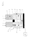
- the only figure of the drawing shows a schematic Sectional view of an assembly device for joining processing of two parts to be connected by means of a joint.
- the invention is of course not based on the illustrated embodiment limited, but in particular are the Shape and basic design of the mounting device of the depending on the processing operation to be performed.
- the measuring device according to the preferred embodiment is explained in connection with a joining process, it is suitable for all those applications without limitation, in which press-in and deformation processes occur, as with Pressing in, deforming, caulking, riveting, flanging or the like.
- part A with part B be connected via a joint.
- part B as an example in a bore 10 in Part A are pressed.
- an assembly aid device designated as a whole by 2 used, which a fixed base plate 3 and a Edition 4 includes.
- the pad 4 is 5 in by means of a guide slidably guided in the vertical direction.
- the edition 4 is movable and resiliently resilient by means of a spring 6 the base plate 3 supported.
- the facing away from the base plate 3 Side of the edition 4 is designed such that the one too connecting part A fits properly and by the support 4 in is positioned in a predetermined manner. Allocating to that second part B to be connected is the edition of a stamp 8 penetrates, which through a through hole 9 in the Edition 4 goes.
- stamp 8 One end of the stamp 8 is on the Base plate 3 while on the opposite end of the Stamp 8 the second part B to be joined or joined rests and is inserted into the through hole 9.
- the second part B to be connected with regard to the first part A to be connected and in particular the aligned there for receiving through hole 10.
- the edition 4 with a another through hole 11 into which a probe 12 is inserted.
- One end of the probe is on the base plate 3 as the stamp 8, while a probe 13 of the probe 12, which is resiliently supported against a surface of one of the parts A, B to be joined or connected, at shown example against a surface of the to be connected Part A.
- the probe is 12 with a device 14 for evaluating and documenting Measurement results connected, which with the help of the probe 12th were recorded.
- the device 14 can then the measurement results thus obtained with the help of the probe 12 evaluate and if necessary according to the wishes of the user document.
- the probe 12 If the probe 12 is used, damaged or dirty is, it can simply from the through hole 11 of the support 4th removed and either cleaned or replaced with a new one become. Elaborate and previously required calibration work and Adjustment work is not required here, as the newly inserted probe 12 as the previous one as well a relative distance measurement with automatic adjustment of Tolerances allowed. If necessary, via the device 14 also reports of good and bad in the manufactured Connection are given so that the bad evaluated connected or joined parts as reject parts can be separated.
- connection work such as joining work
- connection work can be determined, from which it can then be seen that, if appropriate the results of the connection work get worse, from which it can then be seen that the means of a Joining parts A and B to be connected if necessary by From outside the desired tolerance range to avoid the occurrence of a large number of rejects and to be able to take countermeasures at an early stage.
Landscapes
- Physics & Mathematics (AREA)
- General Physics & Mathematics (AREA)
- Engineering & Computer Science (AREA)
- Mechanical Engineering (AREA)
- A Measuring Device Byusing Mechanical Method (AREA)
- Measuring Pulse, Heart Rate, Blood Pressure Or Blood Flow (AREA)
- Eye Examination Apparatus (AREA)
- Length Measuring Devices With Unspecified Measuring Means (AREA)
- Automatic Assembly (AREA)
Claims (6)
- Dispositif de mesure dans un appareil auxiliaire de montage pour jointoiement avec un support (4) qui s'appuie avec un ressort sur une plaque de base (3) et sur lequel repose une partie à relier (A), essentielle pour la détection de la mesure en ce qui concerne le jointoiement, le dispositif de mesure étant posé mobile dans un trou (11) percé dans le support (4) et réalisé en palpeur de mesure (12) qui, par son extrémité opposée à la tête du palpeur (13), s'appuie sur la plaque de base (3) et, pendant le procédé de liaison, appuie sa tête de palpeur (13) contre la partie à relier (A), de façon à détecter le chemin parcouru pendant le procédé de liaison pour évaluer la qualité du jointoiement.
- Dispositif de mesure suivant la revendication 1, dans lequel le support (4) est mobile verticalement au moyen d'un guide (5).
- Dispositif de mesure suivant la revendication 1 ou 2, dans lequel le palpeur de mesure (12) est amovible dans le trou (11) qui passe à travers le support (4).
- Dispositif de mesure suivant une des revendications précédentes, dans lequel le palpeur de mesure (12) est relié à un dispositif (14) d'évaluation et d'enregistrement des résultats de mesure.
- Dispositif de mesure suivant une des revendications précédentes, dans lequel la seconde partie (B) à relier peut être installée dans un trou (10) de la première partie à relier (A) et repose sur un noyau (8) supporté par la plaque de base (3).
- Dispositif de mesure suivant la revendication 5, dans lequel le noyau (8) traverse un trou correspondant (9) à travers le support (4).
Applications Claiming Priority (3)
| Application Number | Priority Date | Filing Date | Title |
|---|---|---|---|
| DE19522503 | 1995-06-21 | ||
| DE19522503A DE19522503A1 (de) | 1995-06-21 | 1995-06-21 | Meßvorrichtung |
| PCT/EP1996/002708 WO1997001077A1 (fr) | 1995-06-21 | 1996-06-21 | Dispositif de mesure |
Publications (2)
| Publication Number | Publication Date |
|---|---|
| EP0834055A1 EP0834055A1 (fr) | 1998-04-08 |
| EP0834055B1 true EP0834055B1 (fr) | 2000-10-11 |
Family
ID=7764873
Family Applications (1)
| Application Number | Title | Priority Date | Filing Date |
|---|---|---|---|
| EP96923885A Expired - Lifetime EP0834055B1 (fr) | 1995-06-21 | 1996-06-21 | Dispositif de mesure |
Country Status (4)
| Country | Link |
|---|---|
| EP (1) | EP0834055B1 (fr) |
| AT (1) | ATE196948T1 (fr) |
| DE (2) | DE19522503A1 (fr) |
| WO (1) | WO1997001077A1 (fr) |
Families Citing this family (2)
| Publication number | Priority date | Publication date | Assignee | Title |
|---|---|---|---|---|
| DE19822204A1 (de) | 1998-05-18 | 1999-11-25 | Scharwaechter Ed Gmbh | Verfahren zum maschinellen Zusammenbau von Schwenkgelenken |
| DE102004048650A1 (de) * | 2004-10-06 | 2006-04-20 | Ina-Schaeffler Kg | Pressverbund sowie Verfahren zur Überwachung und Beurteilung der Qualität eines Pressverbundes |
Family Cites Families (4)
| Publication number | Priority date | Publication date | Assignee | Title |
|---|---|---|---|---|
| SE424151B (sv) * | 1980-06-13 | 1982-07-05 | Holmgren Carl Hugo | Sett och anordning att inom noggranna geometriska toleranser sammanfoga tva vevaxelhalvor |
| JP2620149B2 (ja) * | 1990-06-29 | 1997-06-11 | 武蔵精密工業株式会社 | 圧入状態の検査方法 |
| DE4100410C2 (de) * | 1991-01-09 | 2000-07-06 | Bosch Gmbh Robert | Verfahren zur Überwachung der Qualität einer Preßverbindung |
| JPH06126551A (ja) * | 1992-10-15 | 1994-05-10 | Matsushita Electric Works Ltd | インサート圧入装置 |
-
1995
- 1995-06-21 DE DE19522503A patent/DE19522503A1/de not_active Withdrawn
-
1996
- 1996-06-21 DE DE59605988T patent/DE59605988D1/de not_active Expired - Fee Related
- 1996-06-21 AT AT96923885T patent/ATE196948T1/de not_active IP Right Cessation
- 1996-06-21 WO PCT/EP1996/002708 patent/WO1997001077A1/fr not_active Ceased
- 1996-06-21 EP EP96923885A patent/EP0834055B1/fr not_active Expired - Lifetime
Also Published As
| Publication number | Publication date |
|---|---|
| DE19522503A1 (de) | 1997-01-02 |
| ATE196948T1 (de) | 2000-10-15 |
| EP0834055A1 (fr) | 1998-04-08 |
| DE59605988D1 (de) | 2000-11-16 |
| WO1997001077A1 (fr) | 1997-01-09 |
Similar Documents
| Publication | Publication Date | Title |
|---|---|---|
| DE19521369C2 (de) | Bearbeitungsmaschine zum Umformen von Werkstücken | |
| EP1961502B1 (fr) | Procédé et dispositif destinés au pliage de pièces | |
| DE60130971T2 (de) | Intelligentes werkzeugmaschinensystem | |
| DE60133722T2 (de) | Messeinrichtung für eine, einen Zuschnitt bearbeitende Maschine | |
| DE19843156A1 (de) | Verfahren zur Qualitätssicherung von in einer Crimpvorrichtung hergestellten Crimpverbindungen sowie Crimpwerkzeug und Crimpvorrichtung | |
| DE102004063417A1 (de) | Rohling zur Herstellung zahntechnischer Formteile und Verfahren zur Herstellung des Formteils | |
| AT506313B1 (de) | Biegegesenk für eine biegepresse, insbesondere abkantpresse | |
| DE102019125562A1 (de) | Stanznietvorrichtung und verfahren zum betreiben einer stanznietvorrichtung, um eine inkorrekte matrizenverwendung zu verhindern | |
| EP3120950B1 (fr) | Élément de transmission pour un dispositif de rivetage, dispositif de rivetage, dispositif de fabrication et procé de détermination d'un comportement aux vibrations | |
| DE3407620C2 (fr) | ||
| DE19919693A1 (de) | Verfahren zur Positionsbestimmung eines Preßstempels einer Pulverpresse | |
| DE102018101407B4 (de) | Werkzeugmaschine und Verfahren zur Vorbereitung einer Bearbeitung eines spanabtragenden Rotationswerkzeugs | |
| DE69909579T2 (de) | Verfahren und Vorrichtung zur Bestimmung des Erfolges oder Misserfolges eines Pressfittings | |
| EP0699490B1 (fr) | Dispositif de commande, en particulier pour machines de formage | |
| DE19522503A1 (de) | Meßvorrichtung | |
| DE10041237B4 (de) | Verfahren und Vorrichtung zum Nachweis der Maschinengüte an Anschlagpressen | |
| EP3960318A1 (fr) | Presse de nivellement permettant de niveler une pièce et procédé de nivellement d'une pièce | |
| DE10006512A1 (de) | Abkantpresse mit einer Vorrichtung zum Messen des Biegewinkels am Werkstück | |
| EP0820823A1 (fr) | Dispositif de contrÔle, notamment pour machines de formage | |
| EP1635972B1 (fr) | Procede et dispositif pour travailler des pieces par formage | |
| EP2977196A1 (fr) | Procede de moulage a compensation d'erreurs de positionnement lors du processus de moulage et presse destinee a executer un tel procede | |
| EP1277564A2 (fr) | Procédé de compression de matériaux en poudre | |
| DE29510049U1 (de) | Meßvorrichtung | |
| DE102006056388B3 (de) | Vorrichtung zur Markierung eines Werkstückes, Markierungsprüfeinheit für eine solche Vorrichtung sowie Verfahren zur Markierungsprüfung | |
| CH716048B1 (de) | Verfahren sowie eine Messeinrichtung zum Ausmessen von Utensilien für Pressen. |
Legal Events
| Date | Code | Title | Description |
|---|---|---|---|
| PUAI | Public reference made under article 153(3) epc to a published international application that has entered the european phase |
Free format text: ORIGINAL CODE: 0009012 |
|
| 17P | Request for examination filed |
Effective date: 19980116 |
|
| AK | Designated contracting states |
Kind code of ref document: A1 Designated state(s): AT CH DE FR GB IT LI |
|
| GRAG | Despatch of communication of intention to grant |
Free format text: ORIGINAL CODE: EPIDOS AGRA |
|
| 17Q | First examination report despatched |
Effective date: 19991011 |
|
| GRAG | Despatch of communication of intention to grant |
Free format text: ORIGINAL CODE: EPIDOS AGRA |
|
| GRAH | Despatch of communication of intention to grant a patent |
Free format text: ORIGINAL CODE: EPIDOS IGRA |
|
| GRAH | Despatch of communication of intention to grant a patent |
Free format text: ORIGINAL CODE: EPIDOS IGRA |
|
| GRAA | (expected) grant |
Free format text: ORIGINAL CODE: 0009210 |
|
| AK | Designated contracting states |
Kind code of ref document: B1 Designated state(s): AT CH DE FR GB IT LI |
|
| PG25 | Lapsed in a contracting state [announced via postgrant information from national office to epo] |
Ref country code: IT Free format text: LAPSE BECAUSE OF FAILURE TO SUBMIT A TRANSLATION OF THE DESCRIPTION OR TO PAY THE FEE WITHIN THE PRE;WARNING: LAPSES OF ITALIAN PATENTS WITH EFFECTIVE DATE BEFORE 2007 MAY HAVE OCCURRED AT ANY TIME BEFORE 2007. THE CORRECT EFFECTIVE DATE MAY BE DIFFERENT FROM THE ONE RECORDED.SCRIBED TIME-LIMIT Effective date: 20001011 Ref country code: FR Free format text: LAPSE BECAUSE OF FAILURE TO SUBMIT A TRANSLATION OF THE DESCRIPTION OR TO PAY THE FEE WITHIN THE PRESCRIBED TIME-LIMIT Effective date: 20001011 |
|
| REF | Corresponds to: |
Ref document number: 196948 Country of ref document: AT Date of ref document: 20001015 Kind code of ref document: T |
|
| REG | Reference to a national code |
Ref country code: CH Ref legal event code: NV Representative=s name: PA ALDO ROEMPLER Ref country code: CH Ref legal event code: EP |
|
| REF | Corresponds to: |
Ref document number: 59605988 Country of ref document: DE Date of ref document: 20001116 |
|
| GBT | Gb: translation of ep patent filed (gb section 77(6)(a)/1977) |
Effective date: 20001211 |
|
| EN | Fr: translation not filed | ||
| PG25 | Lapsed in a contracting state [announced via postgrant information from national office to epo] |
Ref country code: GB Free format text: LAPSE BECAUSE OF NON-PAYMENT OF DUE FEES Effective date: 20010621 |
|
| PLBE | No opposition filed within time limit |
Free format text: ORIGINAL CODE: 0009261 |
|
| STAA | Information on the status of an ep patent application or granted ep patent |
Free format text: STATUS: NO OPPOSITION FILED WITHIN TIME LIMIT |
|
| 26N | No opposition filed | ||
| GBPC | Gb: european patent ceased through non-payment of renewal fee |
Effective date: 20010621 |
|
| PGFP | Annual fee paid to national office [announced via postgrant information from national office to epo] |
Ref country code: AT Payment date: 20071228 Year of fee payment: 12 Ref country code: CH Payment date: 20071227 Year of fee payment: 12 |
|
| REG | Reference to a national code |
Ref country code: CH Ref legal event code: PCAR Free format text: ALDO ROEMPLER PATENTANWALT;BRENDENWEG 11 POSTFACH 154;9424 RHEINECK (CH) |
|
| PGFP | Annual fee paid to national office [announced via postgrant information from national office to epo] |
Ref country code: DE Payment date: 20080619 Year of fee payment: 13 |
|
| REG | Reference to a national code |
Ref country code: CH Ref legal event code: PL |
|
| PG25 | Lapsed in a contracting state [announced via postgrant information from national office to epo] |
Ref country code: AT Free format text: LAPSE BECAUSE OF NON-PAYMENT OF DUE FEES Effective date: 20080621 |
|
| PG25 | Lapsed in a contracting state [announced via postgrant information from national office to epo] |
Ref country code: LI Free format text: LAPSE BECAUSE OF NON-PAYMENT OF DUE FEES Effective date: 20080630 Ref country code: CH Free format text: LAPSE BECAUSE OF NON-PAYMENT OF DUE FEES Effective date: 20080630 |
|
| PG25 | Lapsed in a contracting state [announced via postgrant information from national office to epo] |
Ref country code: DE Free format text: LAPSE BECAUSE OF NON-PAYMENT OF DUE FEES Effective date: 20100101 |